background image

Read the operating instructions 

carefully before using the product!

Operating instructions translated from Swedish

27-MD500

MINIDUMPER

Summary of Contents for 27-MD500

Page 1: ...Read the operating instructions carefully before using the product Operating instructions translated from Swedish 27 MD500 MINIDUMPER ...

Page 2: ...set up 7 Recycling 7 Product safety information 8 Environment 8 Chemicals 9 Warning decals 10 Operation Use 12 Load correctly 13 Starting the engine 15 Gear lever 16 Switching off the engine 16 High low speed 16 Hydraulic dump handle 17 Operation 17 Maintenance and service 18 Engineoil filling draining 18 Hydraulic oil filling draining 19 Refilling fuel 20 Grease points 21 Checking and adjusting t...

Page 3: ... spaces with individual track control which minimis es the turning radius and facilitates steering Thanks to the 180 mm track width and the minidumper s length of 1615 cm the pressure is distributed over a larger area thereby enhancing accessibility and protecting the surface you are driving on The track tread pattern also provides a very strong grip on e g clayey soil and snow APPLICATION For exa...

Page 4: ...aldesignofthemachinemustnot underanycircumstances bemodifiedwith outtheapprovalofthemanufacturer Unauthorisedmodificationsand oraccessoriesmay cause life threatening injuries or death to users and others Kellfri is not liable for any modifications changes or rebuilds carried out by customers Where the machine is used professionally employers are responsible for ensuring that users of the machine h...

Page 5: ...work satisfactorily together This is to ensure that the equipment or product works as ex pected and to guarantee the safety of yourself and others Carry out a visual inspection of the equipment or product before use Repair or replace damaged or worn parts immediately to reduce the risk of injury Grease moving parts and check that all nuts and bolts are tightened Repair if necessary Learn and remem...

Page 6: ...oretical and practical knowledge of the machine and that work is performed in a safe manner Stay informed by complying with work environment legislation contact your local work environment authority AFTER USE Ensure that the equipment product is standing on level ground when it is disconnected Use stabilisers if included with the product tool Wash rinse with water and dry if necessary Re lubricate...

Page 7: ... the design and appearance of the product without prior notice TRANSPORTATION AND SET UP Check that the work area is free from bystanders children and objects before driving off Always observe additional caution during transport and moving Ensure that the equipment or product is well anchored and that available transport lashings are fitted Always position the load as low as possible All protrudin...

Page 8: ...se thoroughly with water Avoid breathing in petrol fumes while refuelling Do not keep fuel or other explosive substances near the work zone when using the machine Do not use the machine in the vicinity of flammable gases or fluids Do not try to remove jammed objects while the engine is running Ensure that the engine has stopped before taking action Never allow anyone to travel on the equipment Do ...

Page 9: ... vomiting Drink water in small quantities In the event of ingestion or discomfort contact the poison information service or a doctor Hand protection Wear protective gloves Eye protection Avoid contact with eyes Wear approved protective goggles Body protection Suitable protective clothing Respiratory protection No protection is necessary during normal handling Grease should be stored well sealed in...

Page 10: ...pect the equipment s risk zone WARNING Fire and smoking are prohibited in the vicinity of the machine Risk of fire in the vicinity of fuel WARNING Warning against inhalation of toxic gases WARNING Be aware that parts of the machine may be hot after use Risk of burns WARNING Moving parts Risk of crushing WARNING Keep off the machine WARNING Accident risk for children Children are not allowed in the...

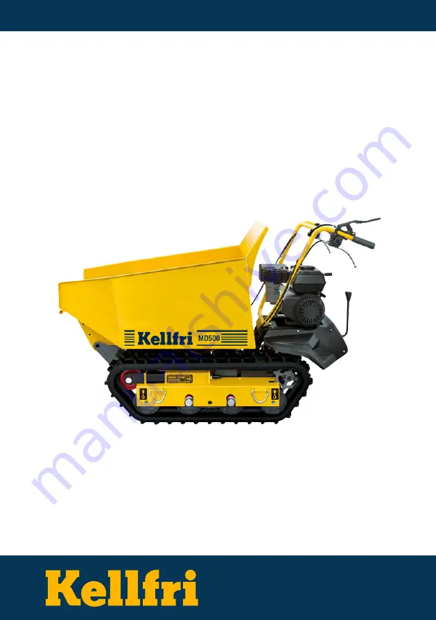
Page 11: ...11 Table of contents HK540G M D500 ...

Page 12: ...ineandloadintoconsiderationandensurethatthebridgeorplatformcanhandlethe weight and that it has guard rails Take care not to drive into objects while operating the minidumper to avoid damaging the machine Onlyswitchgearswhenthemachineisstandingstill Adjustthespeedtoensuresafeoperation Never run Turn by squeezing the steering lever on the side you want to turn towards Take your time to learn how to ...

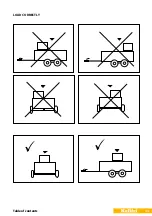
Page 13: ...13 Table of contents LOAD CORRECTLY ...

Page 14: ...gear speed Load bed pin locks the floor to keep it from tipping unintentionally LEVEL SLOPE MAX LOAD Level ground 500 kg 20 25 No Load WARNING The bed of the minidumper must not betippedwhenonaslope thisposes a great risk of tipping over When tipping release the locking hook Remembertorefitthelockinghookduringtransportation driving to avoid unforeseen tipping or floor movements Gear lever Dead man...

Page 15: ...ote The fuel tap must be closed when the machine is not in use during service trans portation of the machine Choke Fuel tap Throttle Pull the starting handle slowly until the mecha nism engages then pull the handle quickly Do not pull the starting cord out fully and do not release the handle when the cord is extended as there is a risk of it getting tangled Repeat until the engine starts SLOW FAST...

Page 16: ...aged HIGH LOW SPEED Gearshift handle High speed mode used in good driving conditions such as good weather and stable ground Otherwise use low speed mode Pull the gear change handle back wards to activate high speed mode Push forward to switch to lowspeedmode SWITCHING OFF THE ENGINE 1 Move the throttle to slow mode 2 Allow the engine to idle for one two minutes 3 Turn the engine switch to the OFF ...

Page 17: ...ith the machine NEVER run The minidumper has a maximum load of 500 kg However it is important to assess the load and adjust it to the terrain on which the machine is being used It is therefore advisable to drive in low gear and to be extra careful Neveroperatethemachineonslopeswithanangleofmorethan20 Avoid sharp turns and frequent changes in direction when driving on rough terrain Even though the ...

Page 18: ...e engine and cause serious damage Never use dirty oil fuel as this can lead to serious damage of the engine Grease the wheels and moving parts such as the throttle and idler bracket regularly WARNING Starttheequipmentoutdoorsorinawell ventilatedarea Donotstarttheequipmentbeforetheareaissecure Ensurethatthegearshiftisinthestoppositionbeforestartingtheenginetoavoidaccidents TOPPING UP DRAINING ENGIN...

Page 19: ...its normal position Top up with hydraulic oil Draining hydraulic oil 1 Make sure the unit is on level ground 2 Place a catch pan under the tap screw 3 Unscrew the tap screw and drain off the oil 4 Screw the tap screw back into place 1 Ensure that the tap screw is tight 2 Unscrew the oil level screw 3 Fill with hydraulic oil via a funnel Capacity 3 5 litres 10W AW32 4 Screw the oil level screw back...

Page 20: ...ere are leaks in the fuel system Loosen the fuel tank cap slowly to reduce the pressure in the tank Never overfill the fuel tank Since the engine s heat can cause the fuel to expand never fill the tank more than 12 mm below the bottom of the filler neck This provides space for fuel expansion We recommend you use alkylate petrol Wipe any spilt fuel with a clean cloth If you accidentally spill fuel ...

Page 21: ...21 Table of contents GREASE POINTS Under the floor in tipping position you will find 2 lubrication points See red marking Grease points NOTE Placed on both left and right sides ...

Page 22: ...drive belt 5 Engage the dead man s grip and fasten to the handlebars e g with plastic ties 6 Check the drive belt tension you should be able to depress the drive belt by 10 12 mm See figure 1 7 Ifthetensionistoohighortoolow adjustatthe cablecasingbracketasshowninfigure2 Remem ber to tighten the nuts on both sides 8 Remove the plastic ties or other fastener hold ing down the dead man s grip 9 Refit...

Page 23: ...sure that the unit is on level ground Take care when lifting the machine on off the pallets risk of crushing WARNING Lifting eye Lifting eye Grease points NOTE Placed on both left and right sides 2 Measure the centre line of the groove versus the horizontal line The reading must not be more than 10 15 mm ...

Page 24: ... must be made on both the right and left hand sides of the minidumper Warning Do not over tighten the drive belt The harder you tighten the drive belt the less effective the braking effect will be NOTE If there is no margin for adjustments with the adjusting bolt the drive belt may need to be replaced Stop the engine before starting service inspection repairs risk of injury Let the engine cool bef...

Page 25: ... the machine and place it on blocks or a pallet which can bear the weight of the machine The tracks must be at least 10 cm above the ground Use blocks or pallets 3 Adjust the bolt M20x180 to move the guide wheel unit towards the drive wheels The drive belt loosens 4 Pull out the loosened drive belts WARNING Risk of crushing Whenremovingorinstallingthe drive belts be careful not to get your fingers...

Page 26: ...e in place see Figure 3 STEERING ADJUSTMENT If the steering becomes difficult to engage Follow the steps below to adjust the cable tension 1 Loosen the awl nut see Figure 1 2 Tighten or loosen the cable by adjusting the adjustment nut see Figure 2 3 When you have the correct cable tension tighten the awl nut to hold the cable in place see Figure 3 Awl nut Adjustment nut Awl nut Awl nut Adjustment ...

Page 27: ... the filter has dried dip it in oil and remove excess oil before using STEERING ADJUSTMENT 2 If previous setting does not provide sufficient cable ten sion followthe steps below 1 Loosen the awl nut see Figure 1 2 Tighten or loosen the cable by adjusting the adjustment nut see Figure 2 3 When you have the correct cable tension tighten the awl nut to hold the cable in place see Figure 3 Locking nut...

Page 28: ...nge the air filter Inspect and clean the system The machine accelerates too slowly when chang ing speeds The throttle cable is stuck Check and adjust The engine overheats Engine oil level low Dirt in the air filter Airflow limited The carburettor has not been adjusted properly Top up with oil Clean the filter Remove the housing and clean See engine manual You press the dead man s grip brake down t...

Page 29: ...d X X Clutch handle Listen for abnormal noises Check the clutch arm release X X X Clutch handle Check the attachment wire and handle for problems X X Low gear Check that levers linkages and screw joints are in one piece and working properly X X X Tension wheel Oil leak around axle X X Chassis Engine Visual inspection of deformities cracks loose miss ing screws screw joints X X X CHECKLIST MAINTENA...

Page 30: ...the maximum load and gradient The machine must never be used to transport animals or people Do not drive into objects with the minidumper s chassis power shaft Do not use the machine to pull loads Warning for crushing risk when driving on slopes or inclines Do not operate the machine on a slope of more than 20 Observe the maximum load per slope gradient LEVEL SLOPE MAX LOAD LEVEL GROUND 500 kg 20 ...

Page 31: ...NG Use caution when operating on slippery surfaces such as gravel Always adjust your speed DANGER Risk of tipping rolling over when transporting heavy loads Never overload the machine Always check your route before starting work Avoid driving over holes or uneven ground If you discover holes or large bumps on the ground mark them to avoid driving over them unintentionally Instructions for emergenc...

Page 32: ...32 Table of contents Item type L Stocked item B Order item ...

Page 33: ... Screw M6x60 1 B 16 R27 MD500 016 Guiding wire 2 L 17 R27 MD500 017 Bolt M10x25 4 B 18 R27 MD500 018 Washer Ø10 8 B 19 R27 MD500 019 Washer Ø10 25 B 20 R27 MD500 020 Bolt M6x12 13 B 21 R27 MD500 021 Nut M8 18 B 22 R27 MD500 022 Washer Ø8 35 B 23 R27 MD500 023 Mounting plate 1 B 24 R27 MD500 024 M6 nut 4 B 25 R27 MD500 025 Return plate 1 B 26 R27 MD500 026 Torsion spring 1 B 27 R27 MD500 027 Washer...

Page 34: ...34 Table of contents ...

Page 35: ... 1 L 50 R27 MD500 050 Tension roller 1 L 51 R27 MD500 051 Clamp ring 15 1 B 52 R27 MD500 052 Screw M5x12 1 B 53 R27 MD500 053 Tensioner arm lower 1 L 54 R27 MD500 054 Washer Ø8 22 B 55 R27 MD500 055 Bolt M8 x 30 1 B 56 R27 MD500 056 Bushing 1 B 57 R27 MD500 057 Pulley small 1 L 58 R27 MD500 058 Bolt M8 x 25 4 B 59 R27 MD500 059 Claw coupling rubber 1 L 60 R27 MD500 060 Claw coupling pump 1 L 61 R2...

Page 36: ...36 Table of contents ...

Page 37: ...086 Short tension spring to lever 1 L 87 R27 MD500 087 Transmission 6 2 1 L 88 R27 MD500 088 Locking nut M10 13 B 89 R27 MD500 089 Long tension spring 1 L 90 R27 MD500 090 Brake wire 1 L 91 R27 MD500 091 Belt guard 1 B 92 R27 MD500 092 Bolt M8 x 60 2 B 93 R27 MD500 093 Press plate 1 B 94 R27 MD500 094 Hose clamp 1 B 95 R27 MD500 095 Rubber cushion 4 B 96 R27 MD500 096 Bolt M8x45 4 B 97 R27 MD500 0...

Page 38: ...38 Table of contents ...

Page 39: ...7 MD500 123 Connection pipe 2 B 124 R27 MD500 124 Guide spring 2 B 125 R27 MD500 125 Guide roller adjustment 2 B 126 R27 MD500 126 Cotter pin 4x35 7 B 127 R27 MD500 127 Swivel castor 2 B 128 R27 MD500 128 Axle pin 2 B 129 R27 MD500 129 Guide roller unit 2 L 130 R27 MD500 130 Hydraulic cylinder 1 L 131 R27 MD500 131 Axle pin 20x95 1 B 132 R27 MD500 132 Plug M14x1 5 3 B 133 R27 MD500 133 Sealing was...

Page 40: ...40 Table of contents ...

Page 41: ...e shoe 1 L 160 R27 MD500 160 Brake protection 1 B 161 R27 MD500 161 Spacer housing 1 B 162 R27 MD500 162 Seal FB17x40x7 2 B 163 R27 MD500 163 Gearbox left 1 B 164 R27 MD500 164 Bearing 6302 1 B 165 R27 MD500 165 Spline shaft 1 B 166 R27 MD500 166 Spline A5x20 2 B 167 R27 MD500 167 Gear 1 R 1 B 168 R27 MD500 168 Gear wheel 2 3 1 B 169 R27 MD500 169 Bearing 6303 5 B 170 R27 MD500 170 Gear shift fork...

Page 42: ...42 Table of contents ...

Page 43: ...D500 195 Bushing 2 1 B 196 R27 MD500 196 Drive unit for 3rd gear 1 B 197 R27 MD500 197 Drive unit for speed H 1 B 198 R27 MD500 198 Intermediate shaft I 1 B 199 R27 MD500 199 Drive unit for speed L 1 B 200 R27 MD500 200 Clamp ring 26 3 B 201 R27 MD500 201 Clutch release fork right 1 B 202 R27 MD500 202 Clutch release fork shaft left 1 B 203 R27 MD500 203 Seal FB16x22x4 2 B 204 R27 MD500 204 Swivel...

Page 44: ...ing 2 B 218 R27 MD500 218 Clutch spring 2 B 219 R27 MD500 219 Gasket 1 4 B 220 R27 MD500 220 Washer 8 10 B 221 R27 MD500 221 Seal FB25x42x7 2 B 222 R27 MD500 222 Composite bush output shaft 4 B 223 R27 MD500 223 Output shaft bushing 2 B 224 R27 MD500 224 Bushing seal 2 B 225 R27 MD500 225 Protective cover 1 B ...

Page 45: ...45 Table of contents HYDRAULIC DIAGRAM Oil cylinder Oil reservoir Oil filter Choke valve Non return valve Oil pump 25MP 2 5 ml r A B T P ...

Page 46: ...engine until it stops This helps to prevent deposits forming inside the carburet tor and causing engine damage While the engine is warm drain the minidumper of old oil and fill with new oil Use clean rags and wipe the machine clean Do not use any strong cleaning agents as these can damage machine parts made of plastic Inspect all screws bolts Tighten any loose screws bolts Repair replace any damag...

Page 47: ...ipment from 2 different angles and 2 close ups of the actual damage from 2 different angles Feel free to attach photos on the next page If the product was purchased from a dealer please contact the dealer in the first instance REASON YES 11 Transport damage 09 Product complaint 04 Wrong goods delivered 03 Wrong quantity Purchaser Customer number Address Invoice number E mail Daytime telephone Cust...

Page 48: ...EC DECLARATION OF CONFORMITY FOR MACHINERY ORIGINAL WARRANTY TERMS AND CONDITIONS The warranty s validity Kellfri s warranty is valid for 12 months from the date of purchase The warranty covers Reimbursement for parts replaced after a material fault or manufac turing fault has been verified The warranty does not cover Labour costs Travel costs A machine that the purchaser himself has modified or h...

Reviews: