background image

Engine Electrical System

General Information

Engine 

,SLJ[YP

cal System

Summary of Contents for Carnival 2009

Page 1: ...Engine Electrical System General Information Engine SLJ YPcal System ...

Page 2: ...ury always use extreme caution and appropriate eye protection when working with batteries KEYPAD The MICRO570 button on the key pad provides the following functions BATTERY TEST PROCEDURE 1 Connect the tester to the battery A Red clamp to battery positive terminal B Black clamp to battery negative terminal Connect clamps securely If CHECK CONNECTION message is displayed on the screen reconnect cla...

Page 3: ...ation for korean manufacturer s for cranking batteries at 18 C 0 F 4 Set the CCA value displayed on the screen to the CCA value marked on the battery label by pressing up and down buttons and press ENTER The battery ratings CCA displayed on the tester must be identical to the ratings marked on battery label 5 The tester Micro570 displays battery test results including voltage and battery ratings A...

Page 4: ...ct measurement value Replace battery Replace battery and recheck the charging system Improper connection between battery and vehicle cables may cause REPLACE BATTERY retest the battery after removing cables and connecting the tester to the battery terminal directly prior to replacing the battery Bad cell replace Charge and retest the battery And then test results may cause REPLACE BATTERY replace ...

Page 5: ...ormal System shows a normal starter draw Cranking voltage low Cranking voltage is lower than normal level Check starter Charge battery The state of battery charge is too low to test amp amp amp amp amp amp gt Charge the battery and retest Replace battery Replace battery If the vehicle is not started though the battery condition of Good and fully charged is displayed Check wiring for open circuit b...

Page 6: ...of generator Press ENTER to test the charging system 3 The MICRO 570 will prompt you to rev the engine until the rev detected It will then collect the data 4 Press ENTER 5 The MICRO 570 will analyze the charging system output at idle for comparison to other readings ...

Page 7: ... test at idle and prompt you to rev the engine The analyzer will determine if the charging system can provide enough current for the demands of the vehicle s electrical system When asked to turn of the accessory loads turn of the blower to high heater the high beam beadlights and rear defogger DO NOT use cyclical loads such as air conditioning or wind shield wipers 8 After the test the MICRO 570 w...

Page 8: ...tor does not supply charging current to battery and electrical load to system fully Check belts and generator and replace as necessary High charging voltage The voltage from generator to battery is higher than normal limit during voltage regulating Check connection and ground and replace regulator as necessary amp amp amp amp amp amp amp gt Check electrolyte level in the battery Excess ripple dete...

Page 9: ...llustration Use Alternator pulley remover wrench 09373 27000 Removal and installation of alternator pulley REFERENCE SERVICE TOOLS Tool Number and name Illustration Use Micro 570 Battery checker Check the battery condition Check the charging and starting system ...

Page 10: ...t Wiring connection loose Tighten loose connection Electronic voltage regulator Replace voltage regulator Charging warning indicator does not go out with engine running Battery requires frequent recharging Drive belt loose or worn Adjust belt tension or replace belt Battery cable loose corroded or worn Inspect cable connection repair or replace cable Electronic voltage regulator or alternator Repl...

Page 11: ...ery Battery cables loose corroded or worn out Repair or replace cables Starter motor faulty Replace Starter keeps running Starter motor Replace Ignition switch Replace Starter spins but engine will not crank Short in wiring Repair wiring Pinion gear teeth broken or starter motor Replace Ring gear teeth broken Replace fly wheel or torque converter ...

Page 12: ...on Alternator Type Battery voltage sensing Rate voltage 13 5 V 110A Speed in use 1 000 18 000 rpm Voltage regulator Electronic built in type Regulator setting voltage 14 2 14 8V Battery Type MF 68AH Cold cranking amperage at 18 C 0 4 F 600 A Reserve capacity 110 min Specific gravity at 20 C 68 F 1 280 0 01 COLD CRANKING AMPERAGE is the amperage a battery can deliver for 30 seconds and maintain a t...

Page 13: ...Engine Electrical System Ignition System Engine Electrical System ...

Page 14: ...e operating conditions are preprogrammed in the memory of the ECM Engine Control Module The engine operating conditions speed load warm up condition etc are detected by the various sensors Based on these sensor signals and the ignition timing data signals to interrupt the primary current are sent to the ECM The ignition coil is activated and timing is controlled ...

Page 15: ...ctor A 2 Remove the ignition coil 3 Using a spark plug socket remove the spark plug Be careful that no contaminates enter through the spark plug holes 4 When replacing the spark plug always use the long reach type spark plug 1 Color Marking Tip A 2 7L Unleaded Yellow Marking Leaded Green Marking 2 Length Tip Tip PT Length A 2 7L B 83 2mm 26 5mm C Others The length is different from the specificati...

Page 16: ...g 4 Install the spark plug to the ignition coil 5 Ground the spark plug to the engine 6 Check is spark occurs while engine is being cranked To prevent fuel being injected from injectors while the engine is being cranked remove the fuel pump A relay from the fuse box Crank the engine for no more than 5 10 seconds 7 Inspect all the spark plugs 8 Using a spark plug socket install the spark plug 9 Ins...

Page 17: ...or B INSPECTION OF ELECTRODES Condition Dark deposits White deposits Description Fuel mixture too rich Low air intake Fuel mixture too lean Advanced ignition timing Insufficient plug tightening torque 2 Check the electrode gap A Standard 1 0 1 1 mm 0 0394 0 0433 in ...

Page 18: ...INSPECT IGNITION COIL 1 Standard 0 0715 0 015 Mesure the resistance between the terminals No 1 and No 3 ...

Page 19: ...Engine Electrical System Charging System Engine SLJ YPcal System ...

Page 20: ...urrent Therefore DC current appears at alternator B terminal In addition the charging voltage of this alternator is regulated by the battery voltage detection system The alternator is regulated by the battery voltage detection system The main components of the alternator are the rotor stator rectifier capacitor brushes bearings and V ribbed belt pulley The brush holder contains a built in electron...

Page 21: ...the battery CHECK THE BATTERY TERMINALS AND FUSES 1 Check that the battery terminals are not loose or corroded 2 Check the fuses for continuity INSPECT DRIVE BELT Visually check the belt for excessive wear frayed cords etc If any defect has been found replace the drive belt Cracks on the rib side of a belt are considered acceptable If the belt has chunks missing from the ribs it should be replaced...

Page 22: ...expected above 0 2V max poor wiring is suspected In this case check the wiring from the alternator B terminal to the battery terminal Check for loose connections color change due to an over heated harness etc Correct them before testing again 3 Upon completion of the test set the engine speed at idle Turn off the headlamps blower motor and the ignition switch OUTPUT CURRENT TEST This test determin...

Page 23: ...headlamps to high beam and the heater blower switch to HIGH quickly increase the engine speed to 2 500 rpm and read the maximum output current value indicated by the ammeter After the engine start up the charging current quickly drops Therefore the above operation must be done quickly to read the maximum current value correctly RESULT 1 The ammeter reading must be higher than the limit value If it...

Page 24: ... terminal of the alternator Connect the lead to good ground or the battery terminal 5 Disconnect the alternator output wire from the alternator B terminal 6 Connect a DC ammeter 0 to 150A in series between the B terminal and the disconnected output wire Connect the lead wire of the ammeter to the disconnected output wire 7 Attach the engine tachometer and connect the battery ground cable TEST 1 Tu...

Page 25: ...tion of the test reduce the engine speed to idle and turn off the ignition switch 3 Disconnect the battery ground cable 4 Remove the voltmeter and ammeter and the engine tachometer 5 Connect the alternator output wire to the alternator B terminal 6 Connect the battery ground cable ...

Page 26: ...Engine Electrical System Charging System Alternator Engine SLJ YPcal System ...

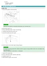
Page 27: ...2009 G 2 7 DOHC COMPONENT ...

Page 28: ...rom alternator B terminal 3 Remove the drive belt 4 Pull out the through bolt and then remove the alternator A 5 Installation is the reverse of removal DISASSEMBLY 1 Remove the alternator cover A using a screw driver B 2 Remove the slip ring guide A 3 Loosen the mounting bolts B and disconnect the brush holder assembly C 4 Remove the rectifler A with 4 screws ...

Page 29: ...pulley A and spacer 6 Loosen the 4 through bolts A 7 Disconnect the rotor A and cover B 8 Reassembly is the reverse order of disassembly INSPECTION INSPECT ROTOR 1 Check that there is continuity between the slip rings A ...

Page 30: ...ft C 3 If the rotor fails either continuity check replace the alternator INSPECT STATOR 1 Check that there is continuity between each pair of leads A 2 Check that there is no continuity between each lead and the coil core 3 If the coil fails either continuity check replace the alternator ...

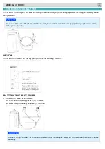
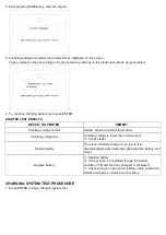
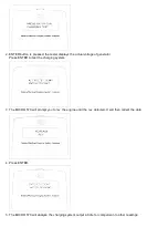
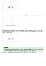
Page 31: ...Engine Electrical System Charging System Battery Engine SLJ YPcal System ...

Page 32: ...nce free battery is as the name implies totally maintenance free and has no removable battery cell caps 2 Water never needs to be added to the maintenance free battery 3 The battery is completely sealed except for small vent holes in the cover ...

Page 33: ...TTERY DIAGNOSTIC TEST 1 CHECKING FLOW LOAD TEST 1 Perform the following steps to complete the load test procedure for maintenance free batteries 2 Connect the load tester clamps to the terminals and proceed with the test as follow ...

Page 34: ...place the battery BATTERY DIAGNOSTIC TEST 2 1 Make sure the ignition switch and all accessories are in the OFF position 2 Disconnect the battery cables negative first 3 Remove the battery from the vehicle Care should be taken in the event the battery case is cracked or leaking to protect your skin from the electrolyte Heavy rubber gloves not the household type should be wore when removing the batt...

Page 35: ...st making sure tops of the terminals are flush with the tops of the posts 11 Tighten the terminal nuts securely 12 Coat all connections with light mineral grease after tightening When batteries are being charged an explosive gas forms beneath the cover of each cell Do not smoke near batteries being charged or which have recently been charged Do not break live circuit at the terminals of batteries ...

Page 36: ...Engine Electrical System Starting System Engine SLJ YPcal System ...

Page 37: ... the ignition key is turned to the start position current flows and energizes the starter motor s solenoid coil The solenoid plunger and clutch shift lever are activated and the clutch pinion engages the ring gear The contacts close and the starter motor cranks In order to prevent damage caused by excessive rotation of the starter armature when the engine starts the clutch pinion gear overruns ...

Page 38: ...tep 4 Disconnect the connector from the S terminal of solenoid Connect a jumper wire from the B terminal of solenoid to the S terminal of solenoid If the starter cranks the engine go to next step If the starter still does not crank the engine remove the starter and repair or replace as necessary 5 Check the following items in the order listed until you find the open circuit A Check the wire and co...

Page 39: ...o starter motor as follows 2 Connect a test ammeter 100 ampere scale and carbon pile rheostats shown is the illustration 3 Connect a voltmeter 15 volt scale across starter motor 4 Rotate carbon pile to the off position 5 Connect the battery cable from battery s negative post to the starter motor body 6 Adjust until battery voltage shown on the voltmeter reads 11volts 7 Confirm that the maximum amp...

Page 40: ...Engine Electrical System Starting System Starter Engine SLJ YPcal System ...

Page 41: ...2009 G 2 7 DOHC COMPONENT ...

Page 42: ...inal E 3 Remove the 2 bolts holding the starter then remove the starter 4 Installation is the reverse of removal 5 Connect the battery negative cable to the battery DISASSEMBLY 1 Disconnect the M terminal A on the magnet switch assembly B 2 After loosening the 3 screws A detach the magnet switch assembly B 3 Loosen the through bolts A 4 Remove the brush holder assembly A yoke b and armature C ...

Page 43: ...emove the shield A and packing B 6 Remove the lever plate A and lever packing B 7 Disconnect the planet gear A 8 Disconnect the planet shaft assembly A and lever B 9 Press the stop ring A using a socket B ...

Page 44: ...se of disassembly Using a suitable pulling tool A pull the overrunning clutch stop ring B over the stopper C INSPECTION ARMATURE INSPECTION AND TEST 1 Remove the starter 2 Disassemble the starter as shown at the beginning of this procedure 3 Inspect the armature for wear or damage from contact with the permanent magnet If there is wear or damage replace the armature ...

Page 45: ...out is not within the service limit replace the armature Commutator runout Standard New 0 02mm 0 0008in max Service limit 0 05mm 0 0020in 6 Check the mica depth A If the mica is too high B undercut the mica with a hacksaw blade to the proper depth Cut away all the mica C between the commutator segments The undercut should not be too shallow too narrow or v shaped D Commutator mica depth Standard N...

Page 46: ...armature INSPECT STARTER BRUSH Brushes that are worm out or oil soaked should be replaced STARTER BRUSH HOLDER TEST 1 Check that there is no continuity between the brush holder A and brush holder B If there is no continuity replace the brush holder assembly 2 Pry back each brush spring A with a screwdriver then position the brush B about halfway out of its holder and release the spring to hold it ...

Page 47: ... both ways Does it lock in one direction and rotate smoothly in reverse If it does not lock in either direction of it locks in both directions replace it 3 If the starter drive gear is worn or damaged replace the overrunning clutch assembly the gear is not available separately Check the condition of the flywheel or torque converter ring gear if the starter drive gear teeth are damaged CLEANING 1 D...

Page 48: ...Engine Electrical System Starting System Starter Relay Engine Electrical System ...

Page 49: ...check that there is continuity between each terminal Terminal Continuity 30 87 NO 85 86 YES 4 Apply 12V to terminal 85 and ground to terminal 86 Check for continuity between terminals 30 and 87 5 If there is no continuity replace the starter relay 6 Install the starter relay 7 Install the fuse box cover ...

Reviews: