background image


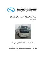
OPERATION MANUAL 

                                                                                    User’s Guide


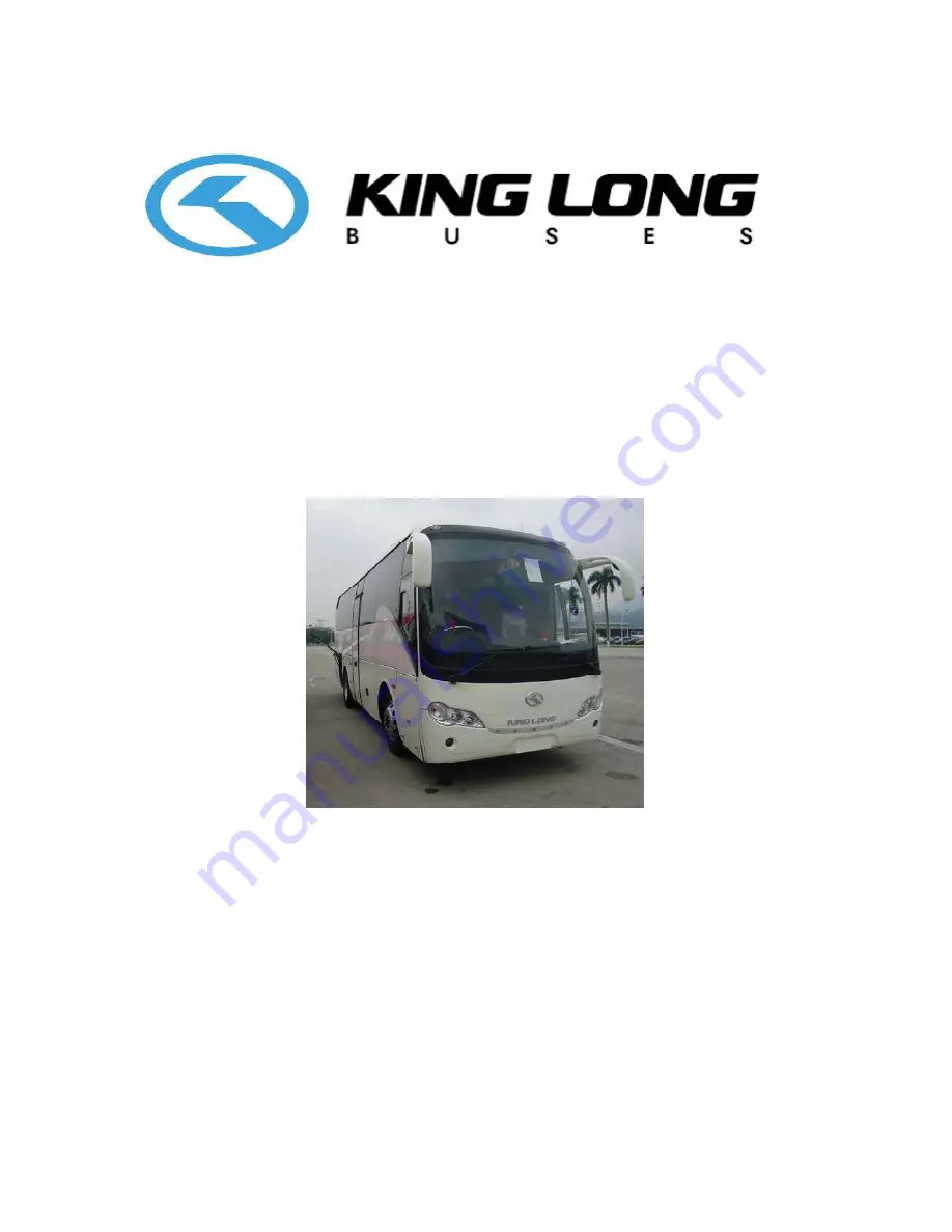
King-Long XMQ6900 Series Tourist Bus 


Xiamen King Long United Automotive Industry Co., Ltd.

Summary of Contents for XMQ6900 Series

Page 1: ...OPERATION MANUAL User s Guide King Long XMQ6900 Series Tourist Bus Xiamen King Long United Automotive Industry Co Ltd...

Page 2: ...hicle and thus the manufacturer Xiamen King Long United Automotive Industry Co Ltd will not takes the responsibility for the damages caused by them Any problem in service please contact our special ma...

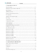
Page 3: ...the driver zone 2 5 3 Operation Instruction Instrument instruction 3 1 Illustration of switch and indicators 3 2 Air conditioner control panel 3 3 Transmission operation 3 4 ABS operation 3 5 ECAS op...

Page 4: ...chometer working order 4 10 Steering wheel play 4 11 Check tire for abrasion and pressure and tire nut for fixture 4 12 Air cleaner 4 13 General leakages water oil fluids and fuel 4 14 Fastening and s...

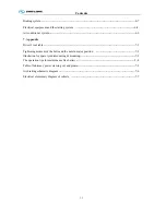
Page 5: ...Fuel recommendation 5 13 Oil quality and specification recommendation 5 14 Breaking in of a new vehicle 5 15 Daily Maintenance Operation 5 16 Maintenance per 5000km 5 17 Maintenance per 10000km 5 18...

Page 6: ...er s tool table 7 1 Tightening moment of the bolts and the nuts in major position 7 2 Illustration for spare tyre dismounting mounting 7 3 The operation tips for maintenance free battery 7 4 Table of...

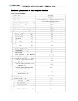
Page 7: ...erall width mm 2480 Overall height mm 3435 Wheelbase mm 4300 Wheel track Front mm 2090 Rear mm 1860 Minimum lift off clearance mm 230 Approach angle 10 departure angle 8 Front suspension rear suspensi...

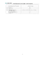
Page 8: ...2 1 parking braking ability 20 gradient parking for 5 minutes Capacity data Fuel tank L 200 Engine oil L 26 5 Transmission lubricant L 42 first oil fill 24 service oil change Main retarder lubricant L...

Page 9: ...e capacity VIN short for vehicle identification number chassis serial number engine serial number engine model rated power production data and etc Chassis data plate The chassis data plate with vehicl...

Page 10: ...st make proper operation and maintenance strictly according to relevant regulations in the instruction book Please refer to workshop manual for product quality assurance and abide by related specifica...

Page 11: ...tric front windshield sunshade driver side sunshade electric driver window safety hammer emergency escaping window curtain and luxury bilateral H type luggage rack engine cabin fire extinguisher elect...

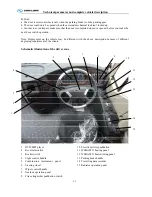
Page 12: ...on the vehicle may be different with the above description because of different deploying requirement of the clients Schematic illustration of the driver zone 1 DVD MP3 player 2 Reversal monitor 3 Roc...

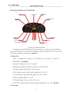
Page 13: ...everse gear N Neutral gear D Drive gear S Safety belt 2 Signal Bar Go to Appendix B 3 Speedometer Display speed of car Units Km h 4 BarometerI and Barometer II Display air pressure of car Units 0 1MPa...

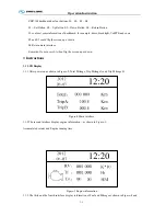
Page 14: ...rn main interface Remarks Do not press S1 when flip the screen up or down 3 Instructions 3 1 LCD Display 3 1 1 After power on as shown in Figure 2 Total Mileage Trip Mileage A and Trip Mileage B Figur...

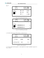
Page 15: ...0000000000 0 L 0000000000 0 L Figure 5 Fuel and Mileage information 3 1 4 The fifth interface display CNG and Catalyst as shown in Figure 6 Figure 6 CNG and CATALYST 3 1 5 The sixth display inside tem...

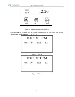
Page 16: ...1 Figure 7 Car and Engine compartment temperature 3 1 6 The seventh eighth ninth tenth and eleventh interface display ECM TCM ABS AIR Retarded information as shown in Figure 8 9 10 11 12 Figure 8 ECM...

Page 17: ...Operation Instruction 3 1 Figure 10 ABS Code Figure 11 AIR Code Figure 12 Retarded Code 3 1 7 The thirteenth interface display online module as shown in Figure 13...

Page 18: ...S1 go to set interface Second Press S2 and S3 flip the interface up or down Could Set Time Set Backlight Set VehPPK Set MotPPR Clear Trip A Clear Trip B ClearTA Clear Oneway OC as shown in Figure 14...

Page 19: ...Operation Instruction 3 1 Figure 17 Set MotPPR Figure 18 Clear Trip A Figure 19 Clear Trip B...

Page 20: ...ime position as shown in Figure 14 Third press S1 go to Figure 22 Figure 22 Set Year Finally press S2 and S3 could increase or decrease years After set year could press S1 choose Month Day Hour Minute...

Page 21: ...3 1 Figure 24 Set Day Figure 25 Set Hour Figure 26 Set Minute 3 2 3 Set Backlight First press S1 go to set interface Second press S2 or S3 choose Set Backlight position as shown in Figure 15 Third pre...

Page 22: ...o set interface Second press S2 or S3 choose Set VehPPK position as shown in Figure 16 Third press S1 go to Figure 28 Figure 28 Set VehPPK Finally press S2 and S3 could increase or decrease VehPPK Aft...

Page 23: ...irst press S1 go to set interface Second press S2 or S3 choose Clear TA position as shown in Figure 20 Third press S1 clear TA and auto return main interface 3 2 9 Clear One way OC First press S1 go t...

Page 24: ...ght Green Front fog light Green ABS Yellow Rear fog light Yellow Preheater Yellow Alarm of oil pressure Red Engine fault Yellow High beam Blue Return Red Alarm of gas pressure Red Clearance Lamp Green...

Page 25: ...t Concentrate lubrication Engine cabin temperature too high Alarm of oil filter Lack water alarm of W C Alarm of oil filter Rear cabin door Rear Door Left cabin door Alarm of Retarded temperature Righ...

Page 26: ...mp OFF Pressed on bottom the luggage cabin lamp ON Ventilator White Pressed on top the ventilator is turned off Pressed on bottom the ventilator is turned on Front fog lamp White Pressed on top the fr...

Page 27: ...monitor power Body Kneeling function switch White Pressed on top turned on body restoration function the body start restoring action Pressed on bottom turned on the body kneeling function the body sta...

Page 28: ...he ignition key to ACC or ON shift thus could supply power for long Front windshield sunshade switch White Pressed on top the sunshade will be raised Pressed on bottom the sunshade will be descended d...

Page 29: ...d on bottom turned on the descend function Driver window pre heating defrosting switch White Pressed on top turned off the defrosting function Pressed on bottom turned on the defrosting function Engin...

Page 30: ...ard indication Red Gearbox oil temperature over heat alarm Red Gearbox fault alarm Yellow Kneeling function work indication Green Body keep 2th height state indication Yellow ECAS alarm indication Red...

Page 31: ...Operation Instruction 3 3 CC350 355 series A C Operation...

Page 32: ...Operation Instruction 3 3...

Page 33: ...Operation Instruction 3 3...

Page 34: ...Operation Instruction 3 3...

Page 35: ...Operation Instruction 3 3...

Page 36: ...econds the fast time setting mode is activated If the ignition is switched off while the heater is operating in the continuous mode the remaining operating time of 15 minutes is displayed and the heat...

Page 37: ...The remaining operating time refers to the time the heater still continues to remain in operation and the ignition switched off 11 Setting the wakeup time A wakeup time can only be programmed on the...

Page 38: ...mode the water valve would open automatically and keep heating for room as far as the room temperature is below the temperature value which the system was already pre established in advance once in MA...

Page 39: ...arbox ZF 6AP1200B Variant with 3 push buttons horizontally arranged details may be different from illustration Fig 1 Fig 2 Operation Instruction as per Fig 1 or Fig 2 panels 1 1 Push button control wi...

Page 40: ...Operation Instruction 3 4 control unit for potential cases see Section 1 3and 1 4 1 1 3 Push button selector position 1 2 Driving range see Section 1 1 consult the vehicle operation instructions...

Page 41: ...Operation Instruction 3 4 1 3 Starting the engine Starts see Section 1 1 2 and the transmission will remain Have to be depressed and subsequently see Section 1 4 1 4 Engaging a gear 1 4 1 Standard...

Page 42: ...th additional functions 1 4 2 1 Additional function Gear Release Procedure as described under 1 4 1 In addition to the cases mentioned under 1 4 1 engagement of a starting will flash see Section 1 1 2...

Page 43: ...Operation Instruction 3 4 1 6 Downhill driving 1 7 Change in direction of travel Continue as described under Section 1 4 1 8 Kickdown forced downshift...

Page 44: ...Operation Instruction 3 4 1 9 Retarder operation...

Page 45: ...Operation Instruction 3 4 Section 1 1 2 1 10 Stopping parking...

Page 46: ...Operation Instruction 3 4 1 11 Towing 1 11 1 Towing vehicle with coaxial transmission 1 11 1 1 Transmission is functioning...

Page 47: ...Operation Instruction 3 4 1 11 1 2 Transmission damage suspected 1 11 2 Towing vehicle with angle drive transmission 1 12 Temperature monitoring...

Page 48: ...Operation Instruction 3 4 1 13 Status monitoring warning lamps selector will flash see Section 1 1 2 1 14 Transmission response to a malfunction see Section 1 14 1...

Page 49: ...Operation Instruction 3 4 1 14 1 Emergency operation...

Page 50: ...Operation Instruction 3 5 WABCO ABS BASIC INTRODUCTION...

Page 51: ...Operation Instruction 3 5...

Page 52: ...Operation Instruction 3 5...

Page 53: ...Operation Instruction 3 5...

Page 54: ...Operation Instruction 3 5...

Page 55: ...Operation Instruction 3 6 ECAS System Introduction for tourist bus use 1 System introduction...

Page 56: ...Operation Instruction 3 6 3 System function...

Page 57: ...Operation Instruction 3 6...

Page 58: ...3 and clockwise rotate key about 90 then anticlockwise rotate handle 4 after that the door would be locked 3 If need open the passage door insert key into the hole 3 and clockwise rotate it about 90...

Page 59: ...ess The model 3 door emergency switch is located inside the door pump cover which is on the top of the door Please rotate the switch and throw open the door in emergency Special attention The door eme...

Page 60: ...river Handle 1 and Handle 2 cushion height adjustment Handle 4 back and forth adjustment Handle 3 adjustment of the driver s weight Left handle backrest angle adjustment Note Number of handles varies...

Page 61: ...It is on the steering wheel The horn is hooting when pressing the button 1 The type of steering wheel may vary with vehicle model Please use the horn only when strictly necessary to warn other driver...

Page 62: ...teering wheel to the desired position After adjusting press the regulating handle or button down to lock the steering column Note Number of handles varies with vehicle model Attention Adjust the steer...

Page 63: ...s after it has been started but never let it run for more than 10 minutes at idle speed If the vehicle does not move increase the fuel to the accelerator modestly to increase the rotational speed of t...

Page 64: ...of this identification Is the Is the headlamp indication The headlamp small lamp meter lamp and width lamp will all be turned on when continuously anti clockwise rotating the handle to position of th...

Page 65: ...INT interval wiper operation step LO Slow wiping HI Quick wiping The wiper may spray water by pressing the end of the handle The shifts of the retarder may be converted by up and down motion of the ha...

Page 66: ...Operation Instruction 3 16 Passenger control panel instruction 1 air outlet 2 service button 3 reading lamp button 4 lamp 5 loudhailer 6 stop button Model 1 6 1 2 5 4 1 2 3 4 Model 2 5 4 2 1 3 Model 3...

Page 67: ...ch according to the above diagrammatic representation and illustration for escaping in case of danger When in emergency and dangerous condition should 1 push upward with hands and make the hatch open...

Page 68: ...ion Instruction 3 18 Safety hammer The safety hammer is located on the side window Please take down the safety hammer and break open the safety window for escaping in case of danger Model 1 Model 2 Mo...

Page 69: ...ice life it applies integrated circuit and designs 5 special relays intermittent wiper relay turning flasher relay lower water level warning controller relay monitor power relay brake light failure wa...

Page 70: ...Operation Instruction 3 20 Switch control box Model CQ2025 CQ2025 A wiring diagram Printed on opposite cover of the switch control box...

Page 71: ...n the engine compartment hood Take out the oil dipstick and clean it with a clean cloth without loose threads and put it back into its place fitting it in completely Once again pull out the dipstick a...

Page 72: ...he system up until the maximum level indication Only use coolant which is recommended c The compensation tank cover should not be opened when temperature of the coolant is still high to avoid being sc...

Page 73: ...n the interior of the fuel tank and the cleaning of the latter should be carried out In order to change the fuel filter element take the vehicle to a Dealer or a King Long Workshop Fuel system dischar...

Page 74: ...time and check fuel pipe for no leakage Ensure sealing performance of fuel tank and wipe up dirt before opening fuel tank Before filling up shut down engine Do not drive vehicle in empty fuel tank Whe...

Page 75: ...the lenses and the quantity of lanterns for each type of vehicle The King Long vehicles leave the factory in strict obeyance of these specifications Traffic safety depends on these factors therefore...

Page 76: ...Blue If the remain volume of AdBlue is less than 6 this lamp will light and the power of engine will be declined forcibly This will cause the emission substandard and it is not good to engine 2 The da...

Page 77: ...the AdBlue spill in skin mild irritation may occur Wash off with soap and water If the AdBlue spill in eye irrigate eyes with large amount of water The AdBlue is Non combustible if heated water evapo...

Page 78: ...Open the water drain valve of air tank to drain oily water fully If too much oily water is bled check to see if desiccant needs to be replaced in air drier This may be avoided when adopting the autom...

Page 79: ...iver information digital display If the oil pressure is too low the oil pressure is automatically shown on the combination instrument Indication of the oil gauge will show a high value after the cold...

Page 80: ...stem The STOP warning light comes on in case of low brake pressure in the service brake circuits Attention If the driver information indicator displays the warning brake pressure and the STOP warning...

Page 81: ...gearbox speed and monitor vehicle speed to avoid engine operating in the danger range red zone When the exhaust brake is operating on down grades select an adequate gearbox speed to keep engine speed...

Page 82: ...the engine at idle gear and straighten the front wheels forwards Turn the steering wheel alternatively to the right and to the left The steering play free movement of the steering wheel is measured on...

Page 83: ...or some time the tires heat and in consequence of the heat the inflation pressure increases Never under any circumstance empty heated tires to reestablish the recommended inflation pressure The pressu...

Page 84: ...y press the dust discharge valve with your hand in order to incomplete the dust which possibly be caught in the internal part maintaining them clear At the same time check clip connecting rubber hose...

Page 85: ...ving 4 14 3 General leakages water oil fluids and fuel Check the engine the transmission the driving axle the steering system the cooling system and the oil pipeline the air pipeline of the complete v...

Page 86: ...t belts Check buckle of the safety belt of the driver seat for normal and ensure for its lockup under the following situations when fastening the safety belt The body dashes forward all of a sudden Th...

Page 87: ...should stop vehicle and switch off engine immediately open the fire button cover and press the fire button start up fire extinguisher 2 Fire extinguisher may start up automatically when it catches fir...

Page 88: ...the windshield wipers when the windshield is dry Before activating the wipers push the head of the wiper lever inward to spray detergent onto the windshield Check surplus of detergent Stop vehicle on...

Page 89: ...ton Model 1 L adjusting left rearview mirror R adjusting right rearview mirror Mirror button push down the arrow headed button to adjust the mirror for 4 directions Model 2 L adjusting left rearview m...

Page 90: ...aulic help however in this condition there will be more steering wheel play and the steering will become noticeably heavier Drive the vehicle very carefully and take it to an authorized King Long Deal...

Page 91: ...ized Dealer or Workshop Fan drive belts If it is necessary to replace the fan drive belts in emergency situations adjust their tension in such a way that upon pressing them with one s thumb in the mid...

Page 92: ...essor drive belt correctly adjusted and do not need to be adjusted periodically Adjusting method of the air conditioner belt is shown in the figure 1 Check tension of belt Apply 98N force to belt with...

Page 93: ...of left or right rear side 1 battery 2 switch control box 3 main power switch To access the battery open the switch control box panel After the vehicle has finished a day s work the main power switch...

Page 94: ...an be put immediately into operation Note a The engine should be running at low middle speed for 3 5 minutes on every day s first starting before the driving b Never race the engine without warming up...

Page 95: ...ing The shift should be switched to the neutral position and power supply shut down Please make necessary inspection of engine and then troubleshoot Cautions Cautions during the winter operation Pleas...

Page 96: ...switch start and activate the back cover course end switch bar in the engine compartment Loosen the switches immediately the engine begins running When the engine is turned on by way of the start swi...

Page 97: ...abruptly to impulse the starting when the vehicle is stuck in the mud or can not start on a spoil road The following problems should also be paid attention to during the driving If abnormal noise or...

Page 98: ...king state Always activate the parking brake when the vehicle is parked Besides activating the parking brake when parking on upward or downward slopes wedge one of the vehicle wheels to avoid the acci...

Page 99: ...periodic inspection and maintenance of bus according to the operation manual to ensure good status During service stop bus on a horizontal road and ensure bus steady and engine stopping Make function...

Page 100: ...ine refer to relevant engine operation and maintenance manual For maintenance of transmission and front rear axle please refer to relative users guide For use and maintenance of other parts of chassis...

Page 101: ...y replacement if damaged 3 Prohibit washing body paint with hot water buck kerosene and other liquid which has damage to oil paint 4 Check connections between body and frame frequently If find somethi...

Page 102: ...ime after maintenance do remember to put the sensor to the limited position along the ring gear direction 5 Make sure that the power is in off position when remove and install the components keep the...

Page 103: ...sconnect ECU Don t use multimeter to measure ECU control box 3 Monitor voltage stability of generator regularly 4 Parts dismantling must be carried out after electric has been shut off and should keep...

Page 104: ...ition as the drawing below after every 8000 km to 10000 km running for proper use and prolonged tire life Four wheel locating condition should be checked dynamic balance and tire transposition be made...

Page 105: ...knut of brake pedal push rod and adjust adjusting nut and then measure the vertical distance from pedal free position to the position where pressing resistance increases apparently when depressing ped...

Page 106: ...ng shop Be careful to use the high strength dissolve fluid Don t damage paint layer Do not directly inject the water into radiator grill on right left back of the bus to prevent the water from enterin...

Page 107: ...g with a clean and dry napery when cleaning the filter cartridge prevent the water from entering the air filter 3 Exclude dust in unloading valve 4 The filter element may be cleaned by hand or by tapp...

Page 108: ...an radiator fin frequently 3 If users do not operate according to requirement resulting in poor engine cooling and grave damage to components 4 If don t comply with this requirement it may cause poor...

Page 109: ...ing coolant please choose the same brand as much as possible in case of sediment If coolant is degenerative replace entirely Coolant specification as shown below the users should choose proper brand a...

Page 110: ...inimum temperature is higher than 4 C 3 No 10 light diesel fuel Suitable for the zone where venture rate is 10 percent and minimum temperature is more than 5 C 4 No 20 light diesel fuel Suitable for t...

Page 111: ...has different oil changing interval Recommended oil changing interval is 12000km Engine oil viscosity Since oil viscosity fluctuated with temperature so the ambient temperature of engine working area...

Page 112: ...rboloid gear oil defined by API and the ambient temperature requirement Clutch oil It is compound brake fluid DOT3 and must fulfill the standard GB10830 98JG3 GB12981 91H2Y3 It should be paid attentio...

Page 113: ...nd draining water in winter and it can prevent forming scale and corroding cooling system Freezing point of the coolant should be noticed to 5 lower than the lowest environment temperature Different t...

Page 114: ...trolyte level 7 Check whether tire pressure has meet requirement 8 Check and see if each transmission gear can engage properly Maintenance during breaking in period 1 Running on smooth and good road s...

Page 115: ...rear suspension carry out when full load 9 Check connections of chassis and driving system according to specified torques Tighten torques please refer to corresponding instructions 10 Check hydraulic...

Page 116: ...Drive belt Check correct No across crack wear or material break off Crankcase breather tube Check Check the breather tube in cold winter cleanup the ice blocking Engine and Accessories Check No damage...

Page 117: ...w 10 use DEXRON II above 10 use C 3 10W Fix bolts of each place Fasten Each fastening bolts not loosening steering arm not loosening steering wheel swift Ball head Lubricate Each turning ball head not...

Page 118: ...adjust it in time The air spring surface Check clean Clean the lubricant grease on the surface the dirt on the piston the abnormal things placed between the piston and air spring The air spring Check...

Page 119: ...6MPa The brake nuts Inspect Inspect fastening of rear brake board s nut 7 7 9 m 150 180 Nm 9m above front 160 205 Nm rear 196 245 Nm The pipe and joint sealing Check Check brake pipe and joint sealing...

Page 120: ...l pump installation Check No leakage Air compressor Check No air oil coolant leakage lock nut and bolt no loosen or damage No carbon deposit Brake system Check No leakage Propeller shaft fastening bol...

Page 121: ...ter core of oil tank N32 which manufactured by Shanghai oi refining factory or ATF or related product which produced IPS40 SB8575D series Change oil and filter core of oil tank Environment temperature...

Page 122: ...elasticity please adjust or change them The height Check adjust Charge the air springs and adjust to the design height then check the wheel base the height of the vehicle body and the two side wheels...

Page 123: ...ble no air leakage safety valve normal pressure at 8Mpa check air reservoir if with seeper replace air drier filter element Electrical equipment Front lamp horn meters and signal Check set complete an...

Page 124: ...ling fan belt tension Check adjust Check each belt without loosening or damage Cooling fan bearing and bolt Check adjust No damage fouling loosening Belt tension pulley bearing Check adjust No damage...

Page 125: ...ean add Radiator Check Radiator without leakage damage fouling Hose without damage clips without loosen or damage Engine suspending Check fasten Connection reliable firm soft mat no distortion layer o...

Page 126: ...0000km or corresponding time interval As for Cummins engine ZF Series products Allison and VOITH products they will apply for their own special oil or grease change interval please refer to the coveri...

Page 127: ...I R I R I R Air filter element C C C C C C R C C C C C R C C C C Check adjust belt I I I I I I I I I I I I I I I I I Check adjust engine idle speed I I I I I I I I I I I I I I I I I Fixing every bolt...

Page 128: ...Free stroke of clutch pedal I I I I I I I I I Clutch oil I I I I I I I I R Clutch cylinder stroke I I I I I I I I I Transmission Transmission if not leaking oil I I I I I I I I I I I I I I I I I Sele...

Page 129: ...I I I I Engine exhaust brake I I I I I ABS unit checking I I I Brake valve other valves I I I Axle Tire Tire steel ring I I I I I I I I I I I I I I I I I Checking fixing RR axle housing differential...

Page 130: ...I I I I Absorber working condition I I I Steel plate suspension bush I I I Left right steel plate suspension flexibility I I I Fixing suspension U type bolt I I I I I I I I I Valves function I I I Br...

Page 131: ...35 40 45 50 55 60 65 70 75 80 Month 1 3 5 7 8 9 10 11 12 Electrical system All lights I I I I I I I I I Battery electrolyte surface connector I I I I I I I I I Wire box installation I I I I I I I I I...

Page 132: ...bricate zones in bus 1 steering drag rod 2 Steering knuckle kingpin front brake self adjusting arm in front axle 3 Rear brake self adjusting arm in rear axle 4 Propeller shaft 5 Engine cabin Part I Lu...

Page 133: ...side have four lubricate points Two are for steering knuckle kingpin lubricating the other two are for front brake adjusting arm lubricating Right side front tire Left side front tire Part III Lubrica...

Page 134: ...Maintenance and service 5 24 Part IV Lubricate points in the propeller shaft There are three lubricate points in the propeller shaft 2 2 3 2 1...

Page 135: ...rt V Lubricate points in engine cabin You may find 2 lubricating points when open the engine cabin one is for A C bracket another is for A C middle idle pulley shaft There will be not these 2 points i...

Page 136: ...age in the fuel inlet pipe Clogging of the fuel supply pump filters and fix or replace 6 Insufficient fuel injection without fuel injection or low injection pressure 6 Check the injector atomization s...

Page 137: ...and sludge in the back of turbine and compressor impellers Clean it 5 middle cooler mangle leave out 5 Check and replace it 6 Fuel line blocked or leaky 6 Check the seal of fuel line and fuel filter c...

Page 138: ...on 4 Check and adjust the valve timing 5 The driving gear is abraded and get too large gap There is knocking sound at the timing gear box cover 5 Check the gear side clearance and change the gear or n...

Page 139: ...embly 8 middle cooler damaged and leaked 8 Repair or replace it Exhaust with white and blue smoke Possible causes Remedies 1 Poor quality fuel and too much water in fuel 1 Replace the fuel 2 Too low c...

Page 140: ...igh oil pressure Possible causes Remedies 1 Too low ambient temperature and too high oil viscosity 1 Use the required grade engine oil Operate at low speed after starting and then check it when the oi...

Page 141: ...s loose or the rubber damping material is aging 1 Remove and let the sliding yoke and the fixing yoke on the same plane 2 Adjust or replace the propeller shaft 3 Replace the bearing 4 Tighten propelle...

Page 142: ...e 2 Use the lubrication of given grade The transmission gear is off the engaging position Transmission 1 Shift fork distorted or worn 2 Abrasion of the lockup ball or the ball on the gear shifter shaf...

Page 143: ...e rear axle improper sound When the vehicle is running 1 Excessive clearance between the driving and the driven gear 2 Abrasion or damage of the bearing 3 Abrasion or damage of the gear 4 Too low oil...

Page 144: ...Clean or replace the ventilation plug 6 Repair or replace the axle housing 7 Adjust or replace the coupling flange 8 Replace the bearing 9 Adjust or replace the axle housing Hub bearing jamming 1 Exc...

Page 145: ...teering gear housing 2 The front axle 1 Unbalance or abrasion of the rim the spoke and the wheel 2 Abrasion of the front wheel bearing 3 Excessive abrasion of the king pin or the bushing 4 Deformation...

Page 146: ...There has fatigue and damage in the front plate spring 3 Bending of the front axle 4 Unsmooth of the braking 5 Looseness of the front hub bearing nut 6 Inequality of the tire pressure 7 Tires with dif...

Page 147: ...icant to the given level 2 Replace the lubricant 3 Replace the ball stud 4 Overhaul and eliminate trouble 5 Measure the backpressure and repair or replace the pipeline in case of the set value exceede...

Page 148: ...6 6 There has oil spillage in the steering oil tank 1 Clogging of the strainer or the filter element 2 There has air in the pipeline 1 Clean the filter strainer or replace the filter element 2 Add th...

Page 149: ...parts 6 Disassemble and clean the braking valve and replace the faulted parts as needed There has abnormal sound when treading the brake pedal 1 The clincher or the bolt is projected because of abras...

Page 150: ...l cylinder cover and the rubber cap 7 Replace it 8 Tighten the U bolt The braking can t be applied under all conditions When compressed air pressure is normal 1 Too short of the brake valve travel 2 T...

Page 151: ...here has air leakage inside the air pipeline 2 The air compressor doesn t work 3 The pressure regulator is improper adjusted or failed because of the impurity entering or air leakage in the brake valv...

Page 152: ...ance Adjust the belt and replace the bearing The charging indicator light doesn t go off during the running and the vehicle is difficult to start 1 The battery is lack of power 2 The generator is dama...

Page 153: ...ntact of the ignition switch or socket loose 2 Unsteady connection of the relay device or the solenoid switch 3 Turnoff of the starter solenoid switch 4 Damage of the starting gear or the gear ring of...

Page 154: ...emperature difference between high and low pressure pipe Air conditioner system has serious leakage Check the system and find out the leakage point and fill the enough refrigerant 3 The low pressure i...

Page 155: ...inspection glass looks yellow Too much water in the system desiccators reaching the saturation the frosting water blocked the expanding valve Change the desiccators and make the vacuum repeatedly and...

Page 156: ...failure or connection problem 3 temperature control sensor installation position not good 4 temperature control switch defective 5 harness connection not reliable 6 Control panel defective 1 change t...

Page 157: ...ator blower not working 1 relay not working 2 battery no charge 3 battery cable confected 4 air blower harness not connected well 5 harness connection not good 6 venting blower cable not connecting we...

Page 158: ...Combination wrench 27 36 Wrench for front wheel hub bearing nut 55 mm hexagon 16 Combination wrench 30 37 Wrench for rear wheel hub bearing nut 110 mm hexagon 17 S double box wrench 13X15 38 Wrench fo...

Page 159: ...Hangzhou sanhua 9T and 9 5T rear axle Socket wrench for wheel nut 32 mm hexagon 1 41 mm hexagon Dongfeng Dena or Hangzhou sanhua 9 5T rear axle 21 mm foursquare 41 mm hexagon 38 mm hexagon Hunan axle...

Page 160: ...40 Connecting nut between upper knuckle and steering knuckle 280 350 Nut trapeze form arm of Steering left and right 350 450 King pin uniform lock nut 25 40 Adjusting nut front wheel hub bearing Min20...

Page 161: ...addle bolt M14X1 5 120 140 Differential house bolt M16 X1 5 220 280 Bolt stopper shim 31 41 Bolt between final drive and rear axle house M12 X1 5 130 150 Wheel bolt M24X1 5 420 490 Connecting nut whee...

Page 162: ...7 1050 774 1480 1092 1774 1308 M30 1420 1047 2010 1482 2400 1770 Torques for bolts with metric fine threads Dimension of bolt Torques N m ft lb 8 8 10 9 12 9 M8 1 26 19 37 27 48 35 M10 1 25 52 38 76 5...

Page 163: ...ts below spare tyre and take them down 2 fetch out the rubber stopper from front step while the crowbar is inserted in the groove belong to hoisting rocker then rotate it anticlockwise you see the spa...

Page 164: ...ain raise until returning back the initial position then the spare tyre could be used after the vehicle leave B Mounting the spare tyre 1 Move the spare tyre under spare tyre s bracket rotate the rock...

Page 165: ...the height that keep rim stick on the lower surface of beam Attention keep alignment between 2 bolts in chassis frame and 2 bolt holes in rim meanwhile assure bolts come out from rim 3 Fasten the whe...

Page 166: ...rature The batteries need not be charging in the 6 months If the storage period overpass more than 6 months it can be used only after charging 3 Charging There exits hydrogen and oxygen in the later c...

Page 167: ...mage Please fix the battery firmly in the battery bracket 5 Maintenance 5 1 There is the indicator of electric charge on the batteries cover When the indicator shows green the batteries use normally W...

Page 168: ...15W 40 be used upwards 10 10W API CH 4 SG be used between 5 20 5W 30 API CH 4 SG be used upwards 25 2 Gear oil could be used between 20 50 2 Power steering oil Fulfill standard please apply DEXRON II...

Page 169: ...Appendix 7 6 Air braking schematic diagram...

Page 170: ...Appendix 7 7 Electric schematic diagram of the complete car 1...

Page 171: ...Appendix 7 7 Electric schematic diagram of the complete car 2...

Page 172: ...Appendix 7 7 Electric schematic diagram of the complete car 3...

Page 173: ...Appendix 7 7 Electric schematic diagram of the complete car 4...

Reviews: