background image

83003502.Kc ECO_Install_Instruction_V03.odt

Page 1 of 39

Install Instructions


Models:  

ECO122L  with IFP
ECO133L  with IFP

0036

Customer

Siemens Helthcare
Allee am Röthelheimpark 2
91052 Erlangen

Manufacturer

ait-deutschland GmbH
Industriestraße 3
95359 Kasendorf 
Germany
T

+49 9228 9977 0

F

+49 9228 9977 149

E

info@kkt-chillers.com

W  

www.kkt-chillers.com

Service Center


KKT chillers, Inc. Servicehotline USA:

765 Dillon Drive
Wood Dale, IL 60191

TF 

+1 866 517 6867  

24/7 Hotline

F

+1 847 734 1601

E

support@kkt-chillersusa.com

Safety first:
The owner of this unit is responsible that everyone who is working on the unit observ the 
safety rules and read the whole Manual/Install instructions and understand it. 
A wrong or sloppy maintained unit could cause high body  risk or even risk of death.

Summary of Contents for ECO 133 L

Page 1: ... 9228 9977 149 E info kkt chillers com W www kkt chillers com Service Center KKT chillers Inc Servicehotline USA 765 Dillon Drive Wood Dale IL 60191 TF 1 866 517 6867 24 7 Hotline F 1 847 734 1601 E support kkt chillersusa com Safety first The owner of this unit is responsible that everyone who is working on the unit observ the safety rules and read the whole Manual Install instructions and unders...

Page 2: ...ces 13 5 3 Type of cable 13 5 4 Length and cable width 13 5 5 Strain relief 13 5 6 Clamps 13 5 7 Fuse 15 5 8 Phase sequence 16 5 9 EMC Compatibility and Grounding 17 5 10 Data cable 18 6 Interface filter panel IFP 20 6 1 Installation of IFP 098 sample 22 6 2 High differences Fill pressure 27 7 Water connection 29 7 1 Pipe material 29 7 2 Relation of pipe diameter to distance between chiller and IF...

Page 3: ...83003502 Kc ECO_Install_Instruction_V03 odt Page 3 of 39 12 Maintenance 38 13 Warranty 38 14 Safety Warnings 39 ...

Page 4: ...K Cold water temperature inlet max 30 C Operating liquid water circuit distilled water and 35 38 Ethylene Glycol Rated water capacity min 7 8 m h Rated water pressure at IFP max 6 0 bar Safety valve water circuit Chiller 3 0 bar Ambient temperature min 20 C max 48 C Cooling capacity 45 0 kW ECO122L Cooling capacity 60 0 kW ECO133L Rated cold water outlet temperature 20 C Temperature of surrounding...

Page 5: ...ansfer cable 50m 164feet POF Spare parts in a box near the pump 3 piece Fuse 10A 3 piece Fuse 50A Coil for Solenoid Valve Temperature Sensor PT1000 Pressure Sensor 30bar Pressure Sensor 10bar filter pad large for fan switch cabinet filter pad small for air switch cabinet outlet water strainer inlet Brass fittings for the connection Chiller inlet outlet and piping on the pump IFP Brass fittings for...

Page 6: ... 35 to max 38 Use ethylene glycol of only one manufacturer e g DOWTHERM SR1 Dow Chemical Safeflow EG Clariant Do not mix two ore more different manufacturer for one water ethylene glycol circuit Open front panel and fill to a pressure of min 1 0 bar 14 5PSI to 1 3bar 21 7PSI via the feed cock when the pump is off After filling check all connections for leakage 4 The static pressure at the IFP pres...

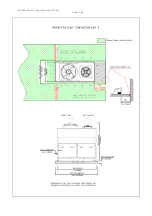
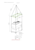
Page 7: ... of the chiller for air intake and servicing repair Under no circumstances install a roof above the chiller 3 3 Servicing and repair access See Clearance 3 4 Air flow Never obstruct the air intake to the condensers on the upper third of the chiller The diameter of the tubes may not be smaller than the size specified 3 5 Load capacity of the base Verify that the installation surface has sufficient ...

Page 8: ...83003502 Kc ECO_Install_Instruction_V03 odt Page 8 of 39 ...

Page 9: ...83003502 Kc ECO_Install_Instruction_V03 odt Page 9 of 39 ...

Page 10: ...7 kg approx 2 595 lbs 4 3 Transport safety locks There are no transport safety locks to remove 4 4 Crane transport If a crane will be used to transport the chiller note the following Lift the chiller only from its base Insert two steel rods through the holes in the base The rods must be specifically designed for this purpose and able to support the weight 800 kg 1 764 lbs Secure the rods with lock...

Page 11: ...83003502 Kc ECO_Install_Instruction_V03 odt Page 11 of 39 ...

Page 12: ...83003502 Kc ECO_Install_Instruction_V03 odt Page 12 of 39 4 5 Dimensions in mm inch ...

Page 13: ...ere to the regulations of the local power company and authorities Only trained authorized persons are permitted to connect the power 5 2 Voltage frequency tolerances Voltage range 380 480 Volt 14 10 Frequency range 50 60Hz 1Hz 5 3 Type of cable Make sure to use appropriately designed and approved cables when routing 5 4 Length and cable width A cable width of at least 16mm per phase is required fo...

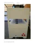
Page 14: ...83003502 Kc ECO_Install_Instruction_V03 odt Page 14 of 39 Do not drill any hole into the unit ...

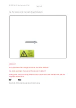
Page 15: ...tograph Attention Do not pass the power supply line across the switch cabinet Use cable opening in the lower left hand side of cabinet Drilling holes into and running cables into the cabinet can cause interferences with the regulation electronics 5 7 Fuse Maximum 80A slow blowing fuse for pre fusing ...

Page 16: ...phase sequence an the phase failure of one of the three phases in a 3 phase network No settings are necessary When the line voltage is switched on the green LED lights up IF the correct phase sequence is applied to the terminals L1 L2 L3 the output relay picks up If the wrong phase sequence is applied the red LED blinks an the output relay does not pick up If a phase failure occurs the red LED lig...

Page 17: ...les is therefore definitely advisable Moreover cable shields must be connected with purpose made ground clips The grounding surface must be highly conductive bare metal Remove any coats of varnish and paint The width of the grounding wire must be min 16mm AWG 6 or of the same width of the power supply The grounding must be an isolated ground and must connected on the ground terminal X1 in the swit...

Page 18: ...e Attach the POF cable end to the RX an TX connector see photograph at the PCB in the control cabinet of the chiller and at the PCB in the control cabinet of the IFP Also use the RX TX connector on the IFP PCB Feed through Run the POF cable from the chiller to the IFP panel ...

Page 19: ...art of delivery from your ECO System 1 Step The connectors are usually protected with a rubber end cap and shall not be removed during installation 2 Step Unroll the cable before installation 3 Step The tensile strength of the CABLE is max 100N The tensile strength of the WIRE is max 5N 4 Step Never slide draggle the cable on the ground or around edges ...

Page 20: ...truction_V03 odt Page 20 of 39 5 Step The bend radius is minimum 12 X outer diameter Outer diameter of the cable is 8mm Bend radius 8mm x 12 Bend radius 96mm à compared to 3 77 6 Interface filter panel IFP Drawing and foot print ...

Page 21: ...83003502 Kc ECO_Install_Instruction_V03 odt Page 21 of 39 ...

Page 22: ...c ECO_Install_Instruction_V03 odt Page 22 of 39 6 1 Installation of IFP 098 sample IPF 090 should be installed simmilarly reguarding free spaces arround the IFP Outer demensions of IFP 098 and IFP090 are the same ...

Page 23: ...d by handling the ball valves The valves allows filling the chiller and the IFP with water ethylene glycol mixture without MR electronic cabinets connected to IFP Water hoses from IFP to the MR electronic cabinets are delivered with the MR System and will installed by Siemens The power supply from the MRI have to be connected to X100 on top of the switch cabinet Harting Connector The CAN Cable fro...

Page 24: ... IFP 090 A removed or non working RS485 Bus will result in a communication error at IFP If communication is lost for over 10 minutes the chiller will proceed with daymode The Data cable POF cable from the Chiller have to be connected to the RX an TX connector see photograph at the PCB in the switch cabinet of the IFP ...

Page 25: ... have to take care for adequate draining of the water glycol mixture please follow the national regulations laws and standards accordingly For the case that the water glycol mixture definitely can NOT be treated as waste water we recommend to provide at site a pail for collecting approx 90 liters approx 25 gallons ...

Page 26: ...83003502 Kc ECO_Install_Instruction_V03 odt Page 26 of 39 Disassembly of the flow limiter ...

Page 27: ... position System is OFF Read the static pressure of your system at the pressure gauge on the IFP panel Chiller lower than the IFP panel 1 2 1 3 bar Limitation 17m below IFP The maximum permitted length of the piping between ECO Chiller and IFP is 45m one way A installed and working automatic Airvent in supply return piping with a correct static pressure will determin most of the failures and is re...

Page 28: ... pressure of your system at the pressure gauge on the IFP panel Chiller higher than the IFP panel 1 7 1 8bar Limitation 8m above IFP Chiller on the same level panel 1 7 1 8bar The maximum permitted length of the piping between ECO Chiller and IFP is 45m one way A installed and working automatic Airvent in supply return piping with a correct static pressure will determin most of the failures and is...

Page 29: ...Use 2 R2 DN 50 or 54 mm copper for up to 25 meters 82 ft of straight pipe Use 2 R21 2 DN 65 or 64 mm copper for up to 45 meters 147 6 ft of straight pipe Distances exceeding 45 meters 147 6 ft are not permitted at using ECO and IFP 7 3 Dimensions of the connections Both the coolant return water ethylene glycol mix from the IFP and the coolant supply water ethylene glycol to the IFP need to have a ...

Page 30: ...83003502 Kc ECO_Install_Instruction_V03 odt Page 30 of 39 On the IFP use also the attached brass fittings ...

Page 31: ... glycol mixture 35 38 ethylene glycol for service Fill with clean water distilled water quality with Ethylene glycol at the rate of min 35 to max 38 Use ethylene glycol of only one manufacturer e g DOWTHERM SR1 Dow Chemical Safeflow EG Clariant Do not mix two ore more different manufacturer for one water ethylene glycol circuit Open front panel and fill to a pressure of min 1 5 bar via the feed co...

Page 32: ...ssel 40 L To maintain a constant pressure in the water circuit SERIAL January 2020 ECO133 2372 The system can be filled as described Remark The expansion vessel is pre ressurized with 0 6bar nitrogen Be aware to check any replacement part by yourself Overall Picture expansion vessel 40l ...

Page 33: ... 1 8bar Chiller lower than the IFP panel 1 2 1 3bar 4 Vent all air by the automatic air vent black or brass coloured small tank on the top of the suction side of pump at the IFP panel and in the piping 5 If static pressure decreases during air vent the water circuit must be refilled with premixed water ethylene glycol 35 38 glycol up to see point 3 6 Now bleed all air out of the system and chiller...

Page 34: ...ge 34 of 39 8 Initial start up 1 Turn on main switch 4Q1 2 After a few seconds the pump starts IF not Press reset if necessary Black button on the control cabinet door All automatic fuses and Motor protection relay are off when the unit is shipped ...

Page 35: ...ans are released They are reactivated once the pressure in the condenser reaches approx 20bars 5 Fans regulate themselves in accordance with the set condenser pressure 6 There won t be any flow if the MR is not installed and the chiller will switch off 9 Settings There are no further settings necessary 10 Control 10 1 Pump Check the direction of rotation of the pump Check any noises the pump makes...

Page 36: ...umption 10 4 Fans Check the power consumption 10 5 Refrigerant pressures The low pressure side should be between 6 0 bar 87 PSI and 8 0 bar 116 PSI The high pressure side should be between 18 bar 261 PSI and 26 bar 377 PSI 10 6 Temperatures Outflow water temperatures should be between 19 C 66 2 F and 22 C 71 6 F Inflow water temperatures should be between 21 C 69 8 F and 27 7 C 81 9 F for the ECO1...

Page 37: ...83003502 Kc ECO_Install_Instruction_V03 odt Page 37 of 39 11 Overview water chiller and IFP ...

Page 38: ...must be carried out by trained personnel from an Authorized KKT chillers Service Partner Maintenance must be carried out by properly trained personnel Only genuine KKT chillers spare parts must be used For ECO122L and ECO133L Ethylene glycol must be added to the rate of 35 38Vol Do not remove the Manual or any other Document from the chiller All the scheduled maintenance operations detailed in thi...

Page 39: ...g Ethylene glycol must be added at the rate of 35 38 of the volume of water anytime otherwise warranty void The rate depends not on the local ambient temperature Don t use automotive antifreeze Voltage is continuous present at the terminals even after the medical device has been switched off Parts in the refrigerant circuit are hot even the Chiller has been switched off Warranty void if manual rem...

Reviews: