


RIDO
8065
- HILO
8065
INSTRUCTION MANUAL
20084 Lacchiarella (MI) - Italy - Via della Levata 1 -Tel. +39-02-8929291
E-mail:
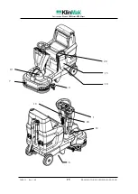
The KlinMak HILO 8065 is a versatile appliance that simplifies daily chores. To maximize its potential, make sure to download the comprehensive Instruction Manual for free from our website. Find all the detailed instructions and operational guidelines you need to unlock the full potential of your HILO 8065.
RIDO
8065
- HILO
8065
INSTRUCTION MANUAL
20084 Lacchiarella (MI) - Italy - Via della Levata 1 -Tel. +39-02-8929291
E-mail:


