background image

Replacement of the bass and volume controls of the Klipsch ProMedia 
Ultra 2.0 speakers

Overview:

Both the bass and volume controls use a linear taper, 50K resistance potentiometer. The bass control is 
single-gang, the volume control is double-gang + rotary switch.  This document describes replacement of 
both potentionmeters with new potentiometers and a seperate toggle switch that takes the position of the 
power LED on the faceplate. To accommodate the new components the faceplate is modified.

Components used:

- Jaycar RP8516 (bass pot – 9mm single-gang linear 50K pot)
- Jaycar RP8710 (volume pot – 9mm double-gang linear 50K pot)
- Jaycar HK7734 (bass and volume knobs)
- NKK G12JPF (illuminated toggle switch)

Tools/other used:

- Screwdriver (say 6mm Phillips and 2mm flat, or thereabouts)
- Soldering iron, solder, wire (thin as possible)
- Hot glue gun
- Drill, drill bits 2.5-12mm, spade bit 10mm
- Spanner/wrench 10mm
- Light sandpaper

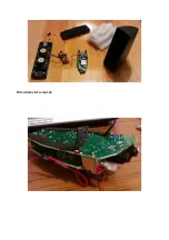
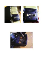
Initial disassembly:

1. Turn the speakers off, remove them from mains power, unplug all cables from the main speaker. 

2. Remove it's dust cover.

3. Remove the ten screws that secure the faceplate.

4. Remove the faceplate.

Note: The faceplate is leashed to the main body by wiring. It is best to lay the unit on it's side from here on.

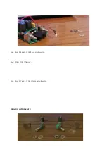
5. Remove the three pieces of packing material.

6. Remove the glue from the power LED and free it from the faceplate.

7. Remove the glue that anchors the speaker wiring to body.

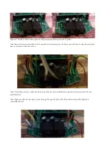
8. Remove the glue from the body where it secures the main PCB.

9. Remove the tape from the body where is secures the main PCB.

10. Remove the two screws that secure the rear-mounted PCB.

11. Slide the main PCB out from the body.

Note: Use a pen or similar object to push the main PCB out from behind.

Summary of Contents for ProMedia Ultra 2.0

Page 1: ...mm flat or thereabouts Soldering iron solder wire thin as possible Hot glue gun Drill drill bits 2 5 12mm spade bit 10mm Spanner wrench 10mm Light sandpaper Initial disassembly 1 Turn the speakers off remove them from mains power unplug all cables from the main speaker 2 Remove it s dust cover 3 Remove the ten screws that secure the faceplate 4 Remove the faceplate Note The faceplate is leashed to...

Page 2: ...Potentiometer removal 1 Remove the knobs from the bass and volume potentiometers 2 Peel back the adhesive pads from the PCB exposing the solder points of the potentiometers and their bracing ...

Page 3: ...ing from the PCB 4 b Flex the potentiometer back and forth to weaken break the pins then use the soldering iron to remove what remains Note Steps 5 7 apply to the volume potentiometer 5 Apply the soldering iron to the two brace solders and use leverage to free it from the PCB 6 There are several small clasps that hold the body of the potentiometer together Using the flathead screwdriver pry them b...

Page 4: ...e red purple sides to maintain a clockwise action 1 Solder new wiring to main PCB board Note Unlike these pictures make sure the wiring is kept as low and backward as possible to allow space for the new potentiometers Note Make sure that the wire doesn t poke through the opposite side of the PCB otherwise it will be difficult to reassemble the unit 2 Surround solders with hot melt glue ...

Page 5: ...nnect the two leads from the LED and the two leads from the old pot switch as per the switch wiring schematic Faceplate modification Information the following picture shows the original faceplate holes in solid and the new larger holes in dash The original knobs have a diameter of 9mm these new parts 12mm The 2 5mm LED is replaced with a 4mm diameter bushed toggle switch Since the LED hole is so c...

Page 6: ...itch use an electric drill and a bit the size of the hole to widen the hole downwards The idea is to enlarge the hole away from the two above it to allow enough space for the new switch 4 Unlike the bass and volume holes the LED hole is surrounded by thicker plastic To get the switch as close to flush at the front as possible countersink the hole using a spade bit In the above picture a regular la...

Page 7: ...the faceplate and hold it there until the glue cools Finished product before and after ...

Reviews: