background image

KMD-5575 

Installation and Operation Guide

Installation and Operation Guide

KMD-5575 Network Repeater-Isolator

873-019-02D

Contents

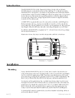
Introduction .........................................................................................................................3
Installation ............................................................................................................................3

Mounting ........................................................................................................................3
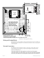
Wiring and Terminal Blocks .........................................................................................4
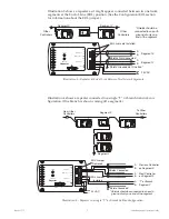
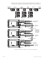
Network Connections ...................................................................................................4

Configuration/EOL

 ........................................................................................................7

Power Connection .........................................................................................................7

Indicators and Operation

 ...................................................................................................8

Accessories ...........................................................................................................................8

Specifications

 .......................................................................................................................8

Summary of Contents for KMD-5575

Page 1: ... Operation Guide KMD 5575 Network Repeater Isolator 873 019 02D Contents Introduction 3 Installation 3 Mounting 3 Wiring and Terminal Blocks 4 Network Connections 4 Configuration EOL 7 Power Connection 7 Indicators and Operation 8 Accessories 8 Specifications 8 ...

Page 2: ...ols Inc Printed in U S A Disclaimer The material in this document is provided for information purposes only The contents and the product s described herein are subject to change without notice KMC Controls Inc makes no representations or warranties with respect to this document In no event shall KMC Controls Inc be liable for any damages direct or incidental arising out of or related to the use of...

Page 3: ...tration 1 shows the major module components and their connections Illustration 1 Components Status LEDs Network 2 Connections Network 1 Connections Power Connection EOL Terminations Circuit Ground Repeater KMD 5575 STATUS 2 1 EOL A B GND EOL A B NETWORK 2 NETWORK 1 24 VAC NETWORK 1 2 Installation Mounting Fasten the KMC KMD 5575 securely to a flat surface inside a metal enclosure using 6 hardware ...

Page 4: ...ower Limited Network Connections The KMD 5575 Network Repeater Isolator is designed to operate between net work segments Each network is connected to the respective terminals on the module See Illustration 1 Connect the shields of the cable together at each device on that segment Connect the shields to an earth ground only at one end of the segment Do NOT connect the cable shield to the circuit se...

Page 5: ...segment Illustration 4 Repeater in a single T or Branch Sublan Configuration 24 VAC A T or Branch B Segment Y A Previous Controller B on Segment X A Next Controller B on Segment X EOL Jumper Removed EOL Jumper Installed Shield Grounded Shields Connected Shields should be connected to an earth ground at only one end of the segment Repeater KMD 5575 STATUS 2 1 EOL A B GND EOL A B NETWORK 2 NETWORK 1...

Page 6: ...one end of the segment Other Segment X Controllers Other Segment X Controllers Repeater KMD 5575 STATUS 2 1 EOL A B GND EOL A B NETWORK 2 NETWORK 1 24 VAC NETWORK 1 2 Repeater KMD 5575 STATUS 2 1 EOL A B GND EOL A B NETWORK 2 NETWORK 1 24 VAC NETWORK 1 2 Repeater KMD 5575 STATUS 2 1 EOL A B GND EOL A B NETWORK 2 NETWORK 1 24 VAC NETWORK 1 2 Shields Connected EOL Jumper Removed EOL Jumper Installed...

Page 7: ...ace a KMC KMD 5567 surge suppressor in the cable run where it exits a build ing For smoke control applications the maximum total length of the MS TP network cable including all repeaters is 4 000 feet The MS TP communications network is supervised in smoke control applications and the ground fault impedance value for the circuit is 0 ohms For specific information on smoke control systems see Smoke...

Page 8: ...15 20 60 Hz 3 VA Class 2 only NOTE All circuits including supply voltage are power limited AC power is non supervised in smoke control applications Baud Rate 9 600 to 38 400 Connections Removable screw terminal blocks wire size 14 22 AWG Network Wiring Belden 82760 or equivalent shielded twisted 18 AWG 5 5 ohms per 1 000 feet and 51 pF foot network connections are supervised in smoke control appli...

Reviews: