background image


Wissenschaftliche Gerätebau Dr. Ing. Herbert Knauer GmbH 

 Hegauer Weg 38 

 D-14163 Berlin GERMANY


Telefon: +49-(0)30 80 97 27-0 

 Fax: +49-(0)30 801 50 10 

 Email: info@knauer.net 

 www.knauer.net


WellChrom 

HPLC-Pump K-120 

HPLC-Pumpe K-120 

Manual / Handbuch 

V7517,  03/2007 

Summary of Contents for WellChrom HPLC-Pump K-120

Page 1: ...bau Dr Ing Herbert Knauer GmbH Hegauer Weg 38 D 14163 Berlin GERMANY Telefon 49 0 30 80 97 27 0 Fax 49 0 30 801 50 10 Email info knauer net www knauer net WellChrom HPLC Pump K 120 HPLC Pumpe K 120 Manual Handbuch V7517 03 2007 ...

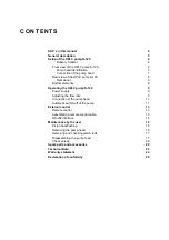
Page 2: ...he HPLC pump K 120 9 Power supply 9 Adjusting the flow rate 9 Connection of the pump head 11 Automatic switch off of the pump 11 External control 13 Remote control 13 Assembling a remote control cable 13 RS 232 interface 14 Maintenance by the user 16 Piston backflushing 16 Removing the pump head 16 Removing and checking piston rods 17 Disassembling the pump head 17 Check valves 20 Spare parts and ...

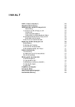
Page 3: ... der Geräteunterseite 28 Bedienung der HPLC Pumpe K 120 29 Netzanschluss 29 Einstellung der Flussrate 29 Anschluss des Pumpenkopfes 31 Sicherheitsabschaltung der Pumpe 31 Externe Ansteuerung 33 Fernsteuerung 33 Konfektionierung der Fernsteuerkabel 33 RS 232 Schnittstelle 34 Wartung durch den Anwender 36 Kolbenhinterspülung 36 Pumpenkopf Wechsel 36 Kolbenstangen ausbauen und prüfen 37 Pumpenkopf ze...

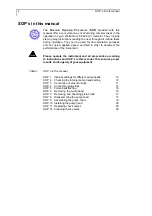
Page 4: ...strument Please operate the instrument and all accessories according to instructions and SOP s in this manual This ensures proper results and longevity of your equipment Table 1 SOP s in this manual SOP 1 Internal settings for different pump heads 10 SOP 2 Checking the internal pump head setting 10 SOP 3 Connection of eluent tubings 11 SOP 4 Connecting plug strips 13 SOP 5 Piston backflushing 16 S...

Page 5: ...0 bar The 50 ml pump head is still pressure stable up to 150 bar The sealings are easily accessible due to the new splitted design Four different older pump heads can also be used with the HPLC pump K 1001 These are the analogous stainless steel and PEEK versions respectively Analytical pump head 0 001 9 999 ml min stainless steel Analytical pump head 0 001 9 999 ml min PEEK Preparative pump head ...

Page 6: ... backflushing 1 PTFE eluent filter 1 Set Inlet screw with fittings 1 Operation Manual 1 Guarantee Statement KNAUER Please fill in the registration card for guarantee and return it immediately Please remove the transparent protective foil from pump outlet and display Front view of the HPLC pump K 120 3 1 2 1 2 2 2 3 Fig 1 shows the front view of the HPLC pump K 120 Various connections three keys an...

Page 7: ...how the maximum flow rate only These older pump heads can easily be identified by their color black biocompatible PEEK version metallic stainless steel version Connection of the pump head All connections for liquids are placed at the front panel of the HPLC pump K 120 Fig 1 and Fig 2 3 1 Capillary connection 3 2 Capillary of backflush 3 3 Pump head screws 3 4 Label max flow rate 3 6 Bushing inlet ...

Page 8: ... there located as well as a RS 232 serial interface 2 for external computer control and remote control input and output 3 START IN connection for START STOP as short circuit or TTL low against ground ERROR OUT output for error signals open collector against ground GROUND ground connection for start and error signals Bottom elements 1 2 3 Fig 4 Bottom elements 1 DIP switch 1 for START IN remote con...

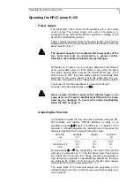
Page 9: ...ernal software is indicated for about 5 seconds on the flow rate display e g 3 1 Never operate the HPLC pump K 120 without liquid in the pump head and the piston backflushing Otherwise the pump head may be damaged To proceed the piston backflushing follow the SOP on page 16 Adjusting the flow rate It is possible to adjust the flow rate either externally using the RS 232 interface see chapter RS 23...

Page 10: ...p head see Fig 4 on page 8 8 Start your pump again by switching it on It will be in the new setting mode SOP 2 Checking the internal pump head setting 1 Switch on the power supply without starting the pump 2 Press the key until the display stops changing You can read now either 10 or 50 3 Readjust to the requested flow rate The actually delivered flow rate is dependent on the back pressure of the ...

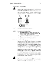
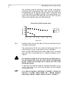
Page 11: ...sible to control the produced back pressure and to switch off the pump if the pressure falls below or exceeds a given limit Indirectly the pressure can be controlled by regulating the power consumption of the pump The power consumption is approxima tely proportional to the back pressure Thus by limiting the power consumption also the maximum pressure reached by the pump can be limited The limitati...

Page 12: ...te with limited power consumption example The exact behavior of the curve varies for each pump head can serve therefore only as an example and not as a standard When using the older PEEK pump heads please keep in mind that they may only be operated up to a maximum pressure of ca 150 bar The maximum positions of the trim screw are dependent on the used pump head They are 10 ml and 50 ml respectivel...

Page 13: ...these contacts will stop the pump This situation corresponds to that on the K 100 pump Switching the DIP switch to the OFF position towards the middle of the instrument inverses the logic of the Start In input The pump works only as long as a short circuit is applied ERROR OUT A signal open collector will be given at this contact if the pump is either halted by an error or if the required rotation...

Page 14: ...ed by the command Fxxxxx Here is xxxxx a 5 digit number representing the flow rate in µl in ASCII code using the numerals 0 to 9 The permissible range depends on the pump head and the corresponding internal setting 10 ml pump head 0 up to 9990 50 ml pump head 0 up to 50000 If the selected flow rate lies outside these limits the command will be ignored and the last entered flow rate will be maintai...

Page 15: ... Current flow rate inquiry Reply Fxxxxx where xxxxx indicates the flow rate in µl T Pump model inquiry 16 characters will be sent back showing the description e g KNAUER MICRO PUMP V Program version inquiry Reply e g V3 1 If using serial control the pump sends the following messages to the PC OK The last command was successfully executed The last command could not be understood and or executed H T...

Page 16: ...e with rinsing liquid 4 Connect the syringe with the tubing 5 Press liquid through the pump head until it flows without any air bubbles into the container 6 Remove tubings from flush opening We recommend connecting both flush openings with a tubing to prevent vaporization of solvents and drying out of the piston chamber If you want operation with continuous backflushing you can attach two containe...

Page 17: ...refully in a straight line If one of the rods is broken the entire pump head needs to be checked for damage Disassembling the pump head SOP 8 Disassembling the pump head All position numbers of the components are related to Fig 9 on page 18 1 Apply SOP Removing and checking piston rods on page 17 2 Loosen the two retaining plate screws item 3 19 half a turn alternating from one to the other to avo...

Page 18: ... from the housing 3 4 3 19 3 18 3 17 3 16 3 15 3 14 3 11a 3 20 3 13 3 21 3 11 3 4 3 12 3 3 3 10 3 10a 3 10a 3 5 3 6 3 22 3 10 3 24 3 23 Fig 9 Explosion view of the pump head Table 3 Parts of the pump head item Description item Description 3 3 Pump head screws 3 15 Springs 3 4 Housing 3 16 Guide for spring 3 5 Bushing inlet 3 17 Piston rod 3 6 Bushing outlet 3 18 Retaining plate 3 10 Check valves i...

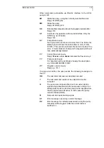
Page 19: ...the ceramic seal holder in place by attaching the check valves 3 10 and distance holder 3 10a according to SOP 12 Cleaning check valves on page 20 5 Place the new O rings 3 21 in the inner side of the pressure plate 3 13 6 Install the pressure plate item 3 13 Take care on the orientation of housing and pressure plate Using the SW 5 16 spanner tighten the spacing bolts 3 14 firmly 7 With the open s...

Page 20: ...ns SOP 11 Replacing check valves 1 Remove the connection to the solvent reservoir 2 Remove the bushing on the inlet side 3 5 The lower check valve 3 10 can now be removed together with the bushing 3 Remove the complete capillary connection 3 22 between the two pump chambers Loosen the screw fittings alternating to avoid bending the capillary 4 Remove the bushing from the outlet side 3 6 5 Remove t...

Page 21: ...e of the seating is facing the valve ball see Fig 11 and assemble the check valve properly Wrong assembly can lead to damage and leakage of the check valve 6 Put the check valves considering the flow direction into the bushing holes 3 5 and 3 6 Screw in the bushings by hand Tighten the bushings carefully with a spanner by about turns To avoid destruction of the ceramics tighten the screws of the c...

Page 22: ...nd O rings 3 11 3 11a for 10 ml pump head 3 21 A1514 2 piston seals high pressure 3 11 3 21 A1414 and O Rings for 10 ml pump head set of piston seals and O rings 3 11 3 11a for 50 ml pump head 3 21 A0981 set of piston seals and O rings 3 11 3 11a for 50 ml pump head 3 21 A0982 especially for aqueous eluents 2 piston seals high pressure 3 11 3 21 A0768 and O Rings for 50 ml pump head piston rod 1 8...

Page 23: ...p head 0 001 9 999 ml min at external control 0 01 9 99 ml min in stand alone mode 50 ml pump head 0 01 49 99 ml min Max Operating Pressure pump head depending 10 ml 40 MPa 50 ml 15 MPa Control RS 232 Interface Remote connections Start Error Display LED Gradient With software control expandable to high pressure gradien system HPG with up to 4 eluents Power Supply 24V 1 5A Dimensions 105 x 100 x 18...

Page 24: ...erät inklusive Zubehör gemäß der SOPs in diesem Handbuch Andernfalls können fehlerhafte Meßergebnisse Beschädigungen oder gesundheitliche Beeinträchtigungen des Anwenders eintreten obwohl dieses Gerät außerordentlich robust und betriebssicher ist Tabelle 1 SOP s in diesem Handbuch SOP 1 Interne Umschaltung bei Pumpenkopfwechsel 30 SOP 2 Überprüfung des eingestellten Pumpenkopfmodus 30 SOP 3 Anschl...

Page 25: ...druckbeständig bis 400 bar Die Dichtungen sind leichter zugänglich da die Pumpenköpfe jetzt in der Mitte geteilt sind Die Pumpenköpfe früherer Ausführung können ebenfalls mit der HPLC Pumpe K 1001 verwendet werden Es handelt sich dabei um die analogen Ausführungen jeweils in Edelstahl oder PEEK Version Analytischer Pumpenkopf 0 001 9 999 ml min Edelstahl Analytischer Pumpenkopf 0 001 9 999 ml min ...

Page 26: ... Werkzeug 1 RS 232 Verbindungskabel 1 WAGO Anschlussleiste 1 5 m Flachbandkabel 10 polig 1 Satz Hinterkolbenspülung 1 PTFE Eluentfilter komplett 1 Satz Einlass Schraubverbindung 1 Handbuch 1 Garantiekarte KNAUER Bitte füllen Sie die Garantiekarte aus und senden Sie diese umgehend an uns zurück Entfernen Sie die transparenten Schutzfolien vom Pumpenausgang und vom Display Vorderseite der HPLC Pumpe...

Page 27: ...eren Edelstahl und PEEK Pumpenköpfe weisen nur die jeweilige maximale Flussrate aus Zwischen den beiden Pumpenkopfarten kann leicht anhand der Farbe unterschieden werden Schwarz Biokompatible PEEK Version Metall Edelstahlversion Pumpenkopf und Flüssigkeitsanschlüsse Alle Flüssigkeitsanschlüsse befinden sich auf der Vorderseite der HPLC Pumpe K 120 Abb 1 und Abb 2 Abb 2 Pumpenkopf 3 1 Verbindungska...

Page 28: ...ie hier die serielle RS 232 Schnittstelle 2 zur externen Computersteuerung der Pumpe und die Remote Control Ein und Ausgänge 3 mit folgender Belegung START IN Anschluss für START STOP als Kurzschluss oder TTL low gegen Masse ERROR OUT Ausgang für ein Fehlersignal open collector gegen Masse GROUND Masseanschluss für Start und Fehlersignal Elemente an der Geräteunterseite 1 2 3 Abb 4 Bedienelemente ...

Page 29: ...ängig von der Stellung des DIP Schalters wird beim Einschalten zunächst für etwa 5 Sekunden die Versions nummer der internen Software z B 3 1 auf dem Display angezeigt Lassen Sie die HPLC Pumpe K 120 niemals ohne Flüssigkeit im Pumpenkopf und der Kolbenhinterspülung laufen Andernfalls kann der Pumpenkopf beschädigt werden Um die Kolbenhinterspülung auszuführen folgen Sie der SOP Kolbenhinterspülun...

Page 30: ...ntsprechend dem neuen Pumpenkopf 8 Schalten Sie die Pumpe wieder ein Sie befindet sich jetzt bei jedem neuen Einschalten in dem zuletzt ausgewählten Modus SOP 2 Überprüfung des eingestellten Pumpenkopfmodus 1 Schalten Sie die Pumpe ein ohne die Förderung zu starten 2 Stellen Sie durch Dauerdruck auf die Taste die maximale Flussrate ein Es wird entweder 10 oder 50 auf dem Display angezeigt 3 Stelle...

Page 31: ...s ein 3 Ziehen Sie die Verschraubung mit dem Schneidring handfest an Sicherheitsabschaltung der Pumpe Die HPLC Pumpe K 120 besitzt keinen Druckaufnehmer Eine Kontrolle des erzeugten Drucks und eine damit verbundene automatische Abschaltung der Pumpe ist daher nicht möglich Aufgrund der Leistungsfähigkeit der Pumpe können jedoch vor allem im unteren Flussbereich sehr hohe Drücke erzeugt werden mit ...

Page 32: ...in Abhängigkeit vom angeschlossenen Pumpenkopf nicht höher als auf die Maximalpositionen 10 ml bzw 50 ml eingestellt werden Für beide PEEK Köpfe sollte die Potentiometerschraube maximal auf etwa 3 gestellt werden keinesfalls dürfen die Einstellungen 10 ml bzw 50 ml gewählt werden Grundsätzlich gilt daß eine externe Druckmessung z B über ein Manometer immer dann vorgenommen werden sollte wenn die G...

Page 33: ...en gilt für die Schalterstellung ON In der Schalterstellung OFF läuft die Pumpe nur wenn solange ein Kurzschluss anliegt und sie stoppt sofort wenn kein Kurzschluss mehr anliegt ERROR OUT An diesem Kontakt wird dann ein Signal open collector ausgegeben wenn die Pumpe aufgrund irgend eines Fehlers anhält oder die erforderliche Drehzahl wegen eines zu hohen Gegendruckes nicht mehr erreicht wird Mit ...

Page 34: ...ragung gelten folgende Spezifikationen 9600 baud 8 bit 1 stop bit kein parity check Im Folgenden werden die Funktionen beschrieben die von einem Computer direkt zur Steuerung an die HPLC Pumpe K 120 ausgegeben werden können Jeder Befehl und ebenso jede der Pumpen Antwortmeldungen OK bzw bei nicht verstandenen oder nicht akzeptierten Befehlen sind mit ENTER abzu schließen Das Einstellen der Flussra...

Page 35: ... off Das zweite Byte gibt den letzten Fehlercode an 0 kein Fehler 1 Motor blockiert 2 Motor manuell über Taste durch den Anwender gestoppt Der Fehlercode wird nach der Ausgabe gelöscht F Abfrage der aktuell eingestellten Flussrate Antwort Fxxxxx wobei xxxxx die Flussrate in µl angibt T Abfrage des Gerätetyps Es werden 16 Zeichen im Klartext mit der genauen Typenbezeichnung des Gerätes zurückgegebe...

Page 36: ...üllen Sie die im Zubehör enthaltene Glasspritze mit einer geeigneten Spülflüssigkeit vorzugsweise mit Wasser 4 Verbinden sie die Spritze mit dem zweiten Schlauchende 5 Drücken Sie die Spülflüssigkeit mit der Spritze durch den Pumpenkopf bis sie blasenfrei in das Auffanggefäß läuft 6 Entfernen Sie die Schläuche von den Spülanschlüssen Verbinden Sie nach dem Spülen die beiden Spülöffnungen des Pumpe...

Page 37: ...8 kann mit einer kleinen Zange leicht herausgezogen werden Fassen Sie die Spitze des Kolbens mit der Zange und ziehen Sie ihn vorsichtig und ohne zu verkanten nach hinten heraus Falls eine Kolbenstange gebrochen ist sollten Sie den gesamten Pumpenkopf auf Schäden untersuchen Pumpenkopf zerlegen SOP 8 Pumpenkopf zerlegen Alle Positionen der Komponenten dieser SOP beziehen sich auf die Abb 9 auf Sei...

Page 38: ...lays 3 12 können nun aus dem Gehäuse 3 4 durch Stauchen desselben auf die Handfläche entfernt werden 3 19 3 18 3 17 3 16 3 15 3 14 3 11a 3 20 3 13 3 21 3 11 3 4 3 12 3 3 3 10 3 10a 3 10a 3 5 3 6 3 22 3 10 3 24 3 23 Abb 9 Explosionsdarstellung des Pumpenkopfes Tabelle 3 Teileliste des Pumpenkopfes Pos Beschreibung Pos Beschreibung 3 3 Montageschrauben 3 15 Druckfeder 3 4 Gehäuse 3 16 Kupplungsbuchs...

Page 39: ...eramikkörper hinein 4 Arretieren Sie die Inlays durch Einbau der Kugelventile und Abstandsstücke gemäß SOP 12 Kugelventil reinigen auf Seite 40 5 Setzen Sie die O Ringe 3 21 in die Innenseite der Druckplatte 3 13 ein 6 Setzen Sie die Druckplatte mit den O Ringen nach unten auf das Gehäuse 3 4 auf Achten Sie darauf dass die Kolbenhinterspülung bezogen auf die Labelbeschriftung nach oben zeigt Versc...

Page 40: ...au der Kugelventile 1 Lösen Sie die Verbindung zum Elutionsmittel 2 Entfernen Sie die Verschraubung der Einlassseite 3 5 aus der Sie dann das untere Kugelventil 3 10 entnehmen können 3 Demontieren Sie die Kapillarverbindung 3 22 zwischen den beiden Pumpenkammern Lösen Sie dabei die Verschraubungen alternierend um ein Verbiegen der Kapillare zu vermeiden 4 Entfernen Sie die Verschraubung der Auslas...

Page 41: ...ldichtung Dichtsitz glänzende Seite Kugelführung Ventilkugel Dichtsitz matte Seite Flussrichtung 90 gedreht Abb 11 Kugelventil Einzelteile 6 Setzen Sie die Kugelventile unter Beachtung der Flussrichtung in die Aussparungen ein und arretieren Sie sie mit den Ein und Auslassverschraubungen Pos 3 5 und 3 6 Ziehen Sie die Verschraubung handfest an und mit einem gängigen Maulschlüssel ca Umdrehungen na...

Page 42: ...dichtungen 3 11 3 11a mit O Ring für 10 ml Kopf 3 21 A1514 2 Kolbendichtungen 3 11 3 21 A1414 hochdruckseitig mit O Ringen für 10 ml Kopf Satz Kolbendichtungen 3 11 3 11a mit O Ring für 50 ml Kopf 3 21 A0981 Satz Kolbendichtungen 3 11 3 11a mit O Ring für 50 ml Kopf 3 21 A0982 bes für wässr Eluenten 2 Kolbendichtungen 3 11 3 21 A0768 hochdruckseitig mit O Ringen für 50 ml Kopf Kolben 1 8 10 ml Pum...

Page 43: ...pf 0 001 9 999 ml min bei externer Steuerung 0 01 9 99 ml min im stand alone Betrieb 50 ml Kopf 0 01 49 99 ml min Druckmaximum Pumpenkopf abhängig 10 ml 40 MPa 50 ml 15 MPa Steuerung RS 232 Schnittstelle Remote Anschlüsse Startp Error Anzeige LED Gradient Mit Softwaresteuerung zu einem Hochdruckgradientensystem HPG mit bis zu 4 Eluenten erweiterbar Stromversorgung 24V 1 5A Abmessungen 105 x 100 x ...

Page 44: ...leistungsbedingungen Die werksseitige Gewährleistung für die WellChrom HPLC Pumpe K 120 beträgt ein Jahr ab Versanddatum Unsachgemäße Bedienung des Gerätes und Folgen einer Fremdeinwirkung sind hiervon ausgenommen Ebenso sind Verschleißteile wie z B Sicherungen Dichtungen Lampen und Verstopfungsschäden sowie Verpackungs und Versandkosten von der Gewährleistung ausgenommen Bitte wenden Sie sich bei...

Page 45: ...10 1 08 2002 Engineering Guidelines 89 392 EWG EMC Ordinance 89 336 EWG EN 6100 3 2 10 2006 EN 61326 1 10 2006 entspricht den folgenden Anforderungen und Produktspezifikationen Niederspannungverordnung 73 23 EWG EN 61010 1 08 2002 Maschinenrichtlinie 89 392 EWG EMV Verordnung 89 336 EWG EN 6100 3 2 10 2006 EN 61326 1 10 2006 The product was tested in a typical configuration Das Produkt wurde in ei...

Reviews: