background image


INSTALLATION AND OPERATION MANUAL 
FOR SUPERTRACK MODEL S4   
Ku-BAND TV-RO ANTENNAS 


KNS Inc. 

Tel)+82-42-932-0351~2 
Fax)+82-42-932-0353 
Web) http://kns-kr.com/ 
 
28.03. 2011


Summary of Contents for SUPERTRACK S4

Page 1: ...INSTALLATION AND OPERATION MANUAL FOR SUPERTRACK MODEL S4 Ku BAND TV RO ANTENNAS KNS Inc Tel 82 42 932 0351 2 Fax 82 42 932 0353 Web http kns kr com 28 03 2011 ...

Page 2: ...t Notice All Rights Reserved The information contained in this document is proprietary to KNS Inc This document may not be reproduced or distributed in any form without the consent of KNS Inc The information in this document is subject to change without notice Copyright 2010 KNS Inc ...

Page 3: ... 95 ACU Ver S1 12 Hong 1 1 05 17 2010 Update text and figures about changed ACU software PCU Ver 1 96 ACU Ver E1 20 Hong 1 2 10 07 2010 Update text and figure about PCU changes from DVB S1 to DVB S2 PCU Ver 2 13 ACU Ver E1 20 Hong 1 3 Mar 28 2011 Add the SCS version PCU Ver 2 21 ACU Ver E1 23 Hong ...

Page 4: ...2 3 1 Front Panel Functions 22 3 2 ACU Display Operation 25 3 3 Set up Mode 27 4 How to Operate SCS 38 4 1 Connect to PC 39 4 2 Selection Area and Satellite 42 4 3 Skew Setting 48 4 4 Antenna State 50 4 5 Selection Area and Satellite 53 Appendix A Example of Setting the Satellite s Parameters Using SCS 64 Appendix B Error Code Definition 69 Appendix C Specifications 72 Appendix D Satellite Informa...

Page 5: ...tion It is recommended that all personnel responsible for operating S4 systems should know which type of system they have read and understand the basic terms and be familiar with the operation of these systems Although installations may be completed by the customer s preferred personnel it is also recommended that personnel be trained in the KNS suite of equipment installation procedures and train...

Page 6: ...s the boat turns 2 The antenna is situated at least 5m away from other transmitting antennae HF VHF and radar that may generate signals that may interfere with the SuperTrack S series antenna The further away the SuperTrack S series antenna is from other such antennae the less impact their operation will have on it The antenna radome assembly should be rigidly mounted on the boat If necessary rein...

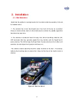
Page 7: ...3 Figure 2 2 Best Location II Figure 2 3 Antenna Blockages ...

Page 8: ...Unit Cut the band and remove the items of antenna equipment Do not turn the box on its side to tip or roll out the product or turn the box upside down to remove it Lift carton box straight up Figure 2 4 Unpack the Antenna ...

Page 9: ...e RF4 coax connection must be plugged into the 18VDC port of your multi switch This must be the horizontal high band input of your four ports Multi switch when using a Quattro LNB NOTE Unused coax connections on the connector bracket MUST be terminated with a 75ohm terminator NOTE We recommend the following cable types for cable lengths within 20m RG6 within 50m RG11 within 100m LMR400 within 200m...

Page 10: ...g 30 pounds of torque Check the label on both ends of each RF cable to match its antenna base plate connector Do NOT use Teflon gel on the cable fittings as it reduces signal strength at high frequencies 2 Install flat washers and spring washers and a mounting bolt to each mounting hole of the radome base from the underside of the mounting surface Apply Loctite 241 to the threads of the mounting b...

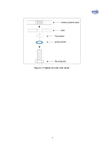
Page 11: ...7 Figure 2 7 Tighten the nuts from below ...

Page 12: ...8 3 Remove the jigs and wire ties holding the Antenna Please refer to Figures 2 8 and 2 9 2 10 below Figure 2 8 Fixed Screw for Elevation Figure 2 9 Fixed Screws for Cross ...

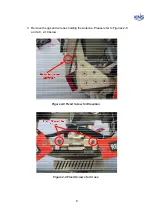
Page 13: ...9 Fixed Screws for Azimuth Figure 2 10 Fixed Screws for Azimuth ...

Page 14: ...placed in a dry location that is convenient for the user 2 It must be situated in a place that is not susceptible to magnetic interference nor must it be situated on a level surface 3 It should be placed so that the LCD display is visible and the buttons are easily accessible Figure 2 11 KA 70 ACU ...

Page 15: ...perTrack S4 receives NMEA type gyro signals when the compass mode is Gyro Connect the NMEA port of the ACU back panel with a ship s gyro using a 9 pin connector female type Figure 2 12 NMEA connector Figure 2 13 Female type 9 pin connector ...

Page 16: ...EA port with the ship s gyro as indicated in Figures 2 14 and 2 15 below Pin No Pin Name 1 RX 2 RX 3 TXD 4 DC 24V 5 GND 6 Dummy 7 GND 8 Dummy 9 Dummy Table 2 1 Using the pin number of the ACU Connector for the NMEA type Figure 2 14 Cable Connection NMEA 422 485 Figure 2 15 Cable Connection NMEA 232 ...

Page 17: ...eceive the various format of NMEA as follow HDT HDG HDM KA 70 ACU ver E 1 23 can accept the gyro signal even though there is no checksum as below HEHDT x x T hh CR LF HEHDG x x x x a x x a hh CR LF hh means checksum of format ...

Page 18: ...and multiple satellite TV receivers To connect the SuperTrack S4 to your satellite TV receiver s choose one of the following configurations based on the number of satellite TV receivers you will connect to the antenna Option 1 Connecting one satellite TV receiver for one satellite Option 2 Connecting one satellite TV receiver for satellite pairs with auto switching Option 3 Connecting satellite TV...

Page 19: ... the antenna s electronics Figure 2 16 One Satellite TV Receiver Installation Connecting one satellite TV receiver for satellite pairs with auto switching Only use the HH polarity of the satellite If you want to use two satellites with one satellite TV receiver you can use automatic satellite switching using the DiSEqC This versatility gives you the capability of receiving audio and video programm...

Page 20: ...ted to the SAT IN connector of the satellite receiver And the ACU connector of the Antenna unit must also be connected to the ANTENNA connector of the ACU In this configuration two satellites can be selected automatically according to the satellite TV receiver signal Refer to the PROGRAM SATELLITE section Figure 2 17 One Satellite TV Receiver with Auto Switching ...

Page 21: ...ver s inputs to the output connectors on the multi switch Connect the multi switch unit in accordance with the manufacturer s instructions Figure 2 18 shows an example of a European multi switch 4 inputs and 4 outputs configuration RF1 Low Band Vertical RF2 Low Band Horizontal RF3 High Band Vertical RF4 High Band Horizontal Figure 2 18 Four Satellites TV Receivers Installation with European LNB If...

Page 22: ...ts the DiSEqC function you can automatically change the satellite using DiSEqC To send the DiSEqC signal to the ACU via the satellite TV receivers one splitter should be installed between the Master satellite TV receiver and the ACU as shown in Figure 2 19 As a result the ACU will receive the signal to change satellites when you change channels using your satellite TV receiver ...

Page 23: ...ertical Low Horizontal Low Horizontal High Vertical High OUT1 OUT2 OUT3 OUT4 4X4 Multiswitch We recommend Aspen s P7002 splitter Power Data RF RF RF RF Passive Splitter DC Pass Master IRD SAT IN TV Figure 2 19 Installation of Four Satellites TV Receivers with European LNB when auto switching the satellite using DiSEqC ...

Page 24: ...should be connected between the antenna unit and the ACU Then connect the RF cable labeled RF4 to the multi switch input labeled LNB LHCP 18V And connect the RF cable labeled RF3 to the multi switch input labeled LNB RHCP 13V The outputs of the multiswitch will then be routed to the individual satellite TV receiver input Use an RF cable with F type connectors for all RF connections Terminate all u...

Page 25: ...iagnostics ANTENNA Antenna Control Unit ACU RECEIVER 13V 18V OUT1 OUT2 OUT3 OUT4 Multiswitch We recommend Aspen s P7002 splitter Power Data RF RF Passive Splitter DC Pass Master IRD SAT IN TV Figure 2 20 Multi satellite TV receiver Installation with Auto Switching ...

Page 26: ...SEARCH shortly again Packet means the number of command from ACU loss means the number of loss on the PCU The more loss this display communication status is not good Figure 3 1 Packet Loss 2 TRACK button Press the TRACK button to enter the stall mode The antenna does not move from the position when the TRACK button is pressed This button is also used to scroll left in the menu 3 NEXT button Press ...

Page 27: ...hat the antenna has distinguished the GSP but that the GPS data is invalid ON indicates that the antenna is receiving valid GPS data OFF indicates that the GPS antenna is not installed or is malfunctioning 9 DiSEqC LED Blinking indicates that DiSEqC option is selected as 22KHz tone ON indicates that the DiSEqC option is selected as DiSEqC 1 2 to switch satellites automatically OFF indicates that t...

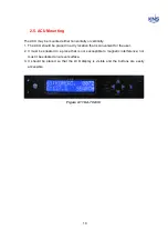
Page 28: ...24 Figure 3 3 Antenna Control Unit Back Panel ...

Page 29: ...ACU displays SEARCH on the LCD when the antenna is searching for the satellite LA N 49 LO E 6 GPS data Tracking In the case of the internal magnetic mode the ACU displays the GPS data on the LCD when the antenna is tracking the satellite If the PCU compass mode is gyro the ACU displays the ship s heading and GPS data on the LCD when the antenna is tracking the satellite The display of the GPS data...

Page 30: ...nna continues in halt mode until the ACU power has been reset Figure 3 5 Display of tracking on gyro mode NOTE For the first power on of the GPS antenna it will take about 5 minutes to calculate your location from the GPS satellites signals and configure the database NOTE Do not push any buttons during the self diagnosis sequence ...

Page 31: ...s the UP or DOWN button The set up mode has 10 sub menus Upgrade The installer or operator can change and configure the current parameters of the S4 by computer Connect the M C port of the ACU to the serial port or the USB port of the computer with an RS 232 cable Female to Female as shown in Figure 3 6 Figure 3 6 Connection ACU with Computer If you want to connect to the PC follow Figure 3 7 or F...

Page 32: ...nd Longitude In the event of invalid GPS data or GPS breakdown you can input the desired latitude and longitude Refer to Figure 3 9 This data will be changed if the GPS data is valid or if the ACU power is reset Figure 3 9 Set Latitude Longitude step ...

Page 33: ...IDs and each area has the parameters of 20 satellites as shown below North America Sat ID 1 20 South America Sat ID 21 40 Europe Sat ID 41 60 Asia Sat ID 61 80 NOTE If you select a different area from your area the ACU will display SH FAIL Searching Fail on the LCD and the antenna will point toward the appointed position after initialization NOTE All satellites on the same area share the LNB local...

Page 34: ...arch for the SAT_A and then if the ACU receives the 22 KHz tone via the receiver port of the AUC back panel the ACU commands the antenna to search for SAT_B But this function requires the 22 KHz tone from the satellite TV receiver NOTE If DiSEqC 1 2 is selected the DiSEqC LED will turn on Also the satellite cannot be changed using the Next button Press MENU hold 2 3 seconds Select the Program Sate...

Page 35: ... can change the skew angle using the Manual Mode The user can also readjust the skew zero position when replacing the PCU skew assembly or potentiometer Press MENU hold 2 3 seconds Select the Skew Angle Setting by or Press MENU Press MENU hold 2 3seconds Press MENU Select Mode by or Press MENU Figure 3 12 Setting the Skew Mode ...

Page 36: ...omatically changes the skew angle when the satellite is changed b Manual Mode The Installer or Operator can change the skew angle to the desired skew angle as shown below Figure 3 13 Setting the Skew Angle in Manual Mode NOTE C refers to the current skew angle A refers to signal strength S refers to the user setting the skew angle ...

Page 37: ...by the skew angle If RESET is selected and MENU is pressed at the desired skew angle the skew angle will be set to 0 degrees The skew angle affects signal strength so we recommend that the user should correct the skew 0 degrees position as shown in Figure 3 14 below Figure 3 14 Skew 0 degrees d Save If you want to save the changed 0 degrees position press MENU after selecting the SAVE mode e Exit ...

Page 38: ...tration inside a building Elevation is changed every 5 by one click of or Azimuth is changed every 10 by one click of or Press MENU Press MENU hold 2 3 seconds Set Azimuth Angle by or Set Elevation Angle or Press MENU to Escape Press MENU hold 2 3 seconds Select the Demo Mode by or Figure 3 14 Setting the Skew Angle in Manual Mode ...

Page 39: ...not recommend use of the Internal Magnetic Mode on metal ships c Gyro Fail Mode Use this mode when a gyro compass is not available The S4 receives the ship s heading as a reference angle when satellite selection or searching or re searching after searching fail And the S4 uses the gyro rate sensor value during searching and tracking d Magnetic Fail Mode Use this mode when an internal magnetic comp...

Page 40: ...e Compass Mode NOTE When using the gyro fail and magnetic fail modes the ship s gyro must not rotate during initializing If the ship s gyro rotates the S4 will not be able to track the satellite due to the incorrect heading angle ...

Page 41: ...e the 5 satellite s name Press MENU Press MENU hold 2 3 seconds Press MENU hold 2 3 seconds Select the Satellite Edit by or Change the Name by or Press MENU Change the Name by or Press MENU Change the Name by or Press MENU Press MENU Change the Name by or Press MENU Change the Name by or Press MENU Figure 3 17 Edit User Settable Satellite Name ...

Page 42: ...S8 of PCU ver 1 93 1 6 1 S3 S4 S6 S6N S8 for PCU ver 1 94 1 7 V SAT Select the V SAT icon S8P S10 S12 of PCU ver 1 924 Select the V SAT icon A6 A9 of PCU ver 2 00 Select the TV RO or A Series icon 1 7 1 V SAT S10 S12 of PCU ver 1 925 Select the V SAT icon A6 A9 S4 S6 S6N S8 of PCU ver 2 11 Select the TV RO or A Series icon 1 7 2 V SAT S10 S12 of PCU ver 2 000 Select the V SAT icon A6 A9 S4 S6 S6N ...

Page 43: ...11 icon and click the OK button then select the COM port of your computer select baud rate 19200 Lastly click the DISCONNECT then S4 is connected with computer Figure 4 1 S4 selection on SCS You can see that CONNECT LED of status panel is on like Figure 4 3 Also you can see the current state of antenna State of antenna is one among Initialize Searching Searching Fail and Tracking HALT ...

Page 44: ...40 1 Select the COM port 2 Select the Baudrate 3 Click the DISCONNECT Figure 4 2 Connection S4 with PC ...

Page 45: ...41 Connection Staus Antenna Current State Figure 4 3 Connection Status S4 with PC ...

Page 46: ...elect satellite in Satellite Select d Press Send to upload to PCU 1 Select the Area 2 Select the S 59 23 5E Astra2ConHigh User1 3 Click to upload Figure 4 4 Select Area and Satellite Step NOTE S4 has 4 areas Europe Asia North America and South America NOTE S4 has 53 satellites 20 satellites in Europe 14 satellites in Asia 13 satellites in North America 6 satellites in South America ...

Page 47: ...tellite name or longitude you can modify this text file and click the List Update select the changed text file Then satellite name or longitude is changed in satellite list But changed satellite is only changed the display name and longitude on the SCS If you want to change the satellite parameters you have to change the satellite parameters in Sat Setting F4 Click Figure 4 5 Satellite List Update...

Page 48: ...44 Figure 4 6 Satellite List Update Step 2 ...

Page 49: ...te s parameters are uploading to parameters panel from PCU c If you want to change the LNB local frequency input the new local frequency and click the OK button to upload to PCU d Change the satellite parameter and click each OK button to upload to PCU If not click after change the parameters changed parameters are not upload to PCU e Press Save to save changed parameters 1 Click 2 LNB Local Frequ...

Page 50: ...erence that used reference during the track the satellite AGC Track the highest AGC level Astra2Connect default C N Track the highest C N level IPcopter default RSSD Receive Signal Detector Track the highest RSSD value Not function RX Polarity means RX polarity of satellite Horizontal Vertical THRD Level means threshold level if searching reference is AGC THD or C N THD Polarity means voltage and ...

Page 51: ...bol means symbol rate of satellite NOTE In case of tracking reference is AGC adjacent satellite s carrier can affect desired satellite s carrier like below Figure 4 8 Hellasat has the adjacent satellite interferences So we set the tracking reference to C N in IPcopter service Sat ID 60 Figure 4 8 Affection of neighborhood satellite NOTE If select the Auto in SCH STD S4 s searching time is slower t...

Page 52: ...mode a Input the desired skew angle in Desired Manual Angle b Click the Skew Manual then skew move to desired angle Skew Mode Setting Input The Desired Skew Angle Figure 4 9 Change the Skew Angle on Manual Mode NOTE In case of S4 s skew is manual mode S4 s skew is not changed when switch the satellite or change the ship position longitude latitude ...

Page 53: ...after select the desired satellite that has skew offset b Look at the Quality then search higher quality by change of skew c Click the Set To Peak after search higher quality d Click the Peak Save to save changed peak e Then S4 s skew is moving to changed skew angle when select this satellite Current Skew Angle Current Signal Level Quality Figure 4 10 Setting Peak Trim NOTE If you want to reset th...

Page 54: ...50 4 4 Antenna State You can see the current state of S4 by SCS like below Click the Antenna State or press F6 Antenna State Figure 4 11 Antenna State ...

Page 55: ...de of satellite current latitude longitude Refer to below step a Input the longitude of satellite current latitude longitude b Click the CALCULATE to calculate c You can see the calculated value in below CALCULATE 1 Input Data 2 Click to calculate 3 Calculated Value Figure 4 12 Calculation of Skew Angle Elevation and Azimuth of Antenna ...

Page 56: ...52 C N You can see the graph of C N on Antenna State Graph of C N Figure 4 13 C N Graph ...

Page 57: ...tilt offset heading offset skew zero setting compass mode when replaced PCU skew block sensor board Click the Installer or press F7 NOTE After change the initial value tilt offset heading offset skew 0 degree position you must click the SAVE to save to PCU Figure 4 14 Saving the Initial Value ...

Page 58: ...t Offset Setting You have to configure the tilt offset when PCU or sensor board is replaced When set the tilt offset use the bubble inclinometer on sensor cage like Figure 4 15 Figure 4 15 Bubble Inclinometer ...

Page 59: ...Refer to below step a Click the Tilt Initial OFF then button is changing to Tilt Initial ON and sensor cage is initializing Click Sensor cage is initializing Figure 4 16 Start the Adjustment of Tilt Offset ...

Page 60: ...56 b Click the Cur Value to request the current tilt sensor offset from PCU Click to call the current value Figure 4 17 Request the Current Tilt Offset ...

Page 61: ...s in center d Click the Tilt Offset to upload to PCU 1 Change the value 2 Click to upload Figure 4 18 Edit Tilt Offset NOTE Click the Command button after input the Ibd in below box of Command is same function click the Tilt Offset Figure 4 19 Request Current Tilt Offset Using Ibd Command ...

Page 62: ...ch the satellite refer to ship s gyro so heading offset must be correct except using internal magnetic Figure 4 20 Initial Heading offset Bow mark of S4 radome base is aligned the ship s bow If not align you must setup new heading offset Refer to below step a Input the desired heading offset in D1 box b Click the HD Offset c Confirm the new heading offset ...

Page 63: ...59 Figure 4 21 New Heading offset Figure 4 22 Setting New Heading offset NOTE When set the heading offset feed has to direct to desired direction ...

Page 64: ...e in manual value box b Click the Skew Manual c Confirm the new skew 0 degree position d If it is correct click the Reset to Zero and if it is incorrect re try the upper steps Figure 4 23 Setting New Skew 0 degree Position NOTE 0 degree position is aligned the LNB top side with cross pulley Figure 4 24 Setting New Heading offset ...

Page 65: ...ent compass mode from PCU S4 has 4 compass mode Gyro Gyro Fail Internal Magnetic and Internal Magnetic Fail Secondly then select the compass mode after click the and click the Setting to upload to PCU Then S4 is initializing and compass mode is changed Figure 4 25 Request the Current Compass Mode Figure 4 26 Setting the Compass Mode ...

Page 66: ... or breakdown A Input the latitude and longitude B If change the North or South and East or West click the North or South and East or West C Click the Set GPS Figure 4 27 Setting the GPS Data NOTE If click the Cur Value current GPS data is displayed in GSP panel ...

Page 67: ...us c Click the Axis Set to set the axis set then change maximum and minimum value of graph d Click the Data OFF to see the graph e Click the Data ON to stop the graph 1 Select the Desired Item 2 Click the ON to Select the Submenus 3 Set th Max and Min Value of Graph 4 Click the Data OFF to Run the Graph Figure 4 28 Graph View NOTE Click the HELP button then you can see the index of graph ...

Page 68: ...ollow the steps outlined below Satellite Longitude RF Frequency Symbol Rate Polarity User1 E23 5 10 803MHz 22 000KHz Horizontal Table A 1 Default Satellite Parameters in User 1 Satellite Longitude RF Frequency Symbol Rate Polarity Astra2Connect E13 12 437MHz 27 500KHz Horizontal Table A 2 Desired Satellite Parameters Connect ACU with PC and press and hold 2 3 seconds the M C of ACU front panel Run...

Page 69: ...he Sat Select or press F3 Select the EUROPE in Zone Select Select the S 58 023 5E Astra2ConLow User1 in Satellite Select Click the Send to upload to PCU 1 Select the Area 2 Select the S 59 23 5E Astra2ConHigh User1 3 Click to upload ...

Page 70: ...the desired satellite s parameters then sat ID 59 satellite s parameters is updating in Satellite Setting Panel Change the LNB Freq Symbol like below Figure Click the OK in right side of changed parameters to upload to PCU 1 Change the RX Frequency 2 Change the Symbol Rate 3 Click ...

Page 71: ...67 Click the SAVE to save to PCU Click to Save ...

Page 72: ...68 Click the Auto Search to search the satellite Click to Start the Searching Then S4 search and track the desired satellite ...

Page 73: ...ss the MENU button on the front panel of the ACU when the error LED is on Then you will see the hexadecimal error code as shown in Fig C 1 below Figure B 1 Error Code on ACU You will also be able to see the hexadecimal error code on the SCS V 1 7 1 as shown in Figure B 2 below Error Code Error LED Figure B 2 Error Code on SCS ...

Page 74: ... 2 The hexadecimal error code 0X 20 00 00 07 Convert to the binary error code 0X 00100000 00000000 00000000 00000111 Error refers to the 7th error of the DBS tuner error Error Code Define PCU Version after 1 94 Syntax 0x FF 1 FF 2 FF 3 FF 4 0x FF 1 18171615 14131211 11 Level motor driving error clear if it returns to normal state in time 12 Cross motor driving error clear if it returns to normal s...

Page 75: ...s been received 0x04 Unknown or invalid data has been received 0x05 The TS command must be sent prior to the command This is for programming the transponder satellite data 0x06 A tuner I2C bus failure has occurred This could indicate that the tuner is defective 0x07 The LNB polarity voltage is not within the LNB polarity range This could indicate that the LNB voltage does not change or that the LN...

Page 76: ...oss Angle 35 Tracking Speed More than 90 sec Platform 3 axis Elevation Angle 20 to 95 GPS Yes Vibration Damper Rubber Damper DiSEqC DiSEqC 1 2 Temperature 25 C to 55 C Humidity Up to 100 40 C Below Deck ACU Size 221 x 153 x 50mm External I O RS232C Input Power 110 220 VAC Gyro Compass Input NMEA Option Output Power 24VDC 60W Packing Size 57 x 57 x 79cm Gross Weight 25Kg Packed by Paper carton Spec...

Page 77: ...0 Conus 08 121 0 W Echostar9 HH 0 DVBQ Auto 11 972 000 20 000 000 Ku 09 129 0 W Ciel2 RH 0 DVBQ Auto 12 457 000 21 500 000 Conus 10 072 0 W AMC 6 VH 0 DVBQ Auto 12 148 000 2 573 000 Ku 11 101 0 W AMC4 HH 0 DVBQ Auto 12 060 000 26 700 000 North Central America 12 97 0 W Galaxy19 HH 0 DVBQ Auto 12 152 000 20 000 000 North America KU 13 89 0 W Galaxy28 HH 0 DVBQ Auto 11 787 000 15 915 000 North Ameri...

Page 78: ...HH 0 DVBQ Auto 11 960 000 30 000 000 Mexico 29 058 0 W User 6 HH 0 DVBQ Auto 11 960 000 30 000 000 Mexico 30 058 0 W User 7 HH 0 DVBQ Auto 11 960 000 30 000 000 Mexico 31 058 0 W User 8 HH 0 DVBQ Auto 11 960 000 30 000 000 Mexico 32 058 0 W User 9 HH 0 DVBQ Auto 11 960 000 30 000 000 Mexico 33 058 0 W User 10 HH 0 DVBQ Auto 11 960 000 30 000 000 Mexico 34 058 0 W User 11 HH 0 DVBQ Auto 11 960 000 ...

Page 79: ... 476 000 28 000 000 Nordic Central Eastern Europe 49 26 0E Bard6 HH 0 DVBQ Auto 11 843 000 27 500 000 BSS 50 7 0W Nilesat102 HH 0 DVBQ Auto 11 996 000 27 500 000 Middle East 51 42 0E Turksat2A HH 0 DVBQ Auto 12 015 000 27 500 000 East 52 7 0E Eutelsat W3A HH 0 DVBQ Auto 12 690 000 2 894 00 Europe B 53 15 8E Eutelsat Seasat1 HH 0 DVBQ Auto 12 525 000 30 000 00 Fixed 54 10 0E Eutelsat W2A HH 0 DVBQ ...

Page 80: ...S4 HH 0 DVBQ Auto 12 647 000 27 500 000 India 69 156 0E Optus C1 HH 0 DVBQ Auto 12 689 000 27 800 000 NB 70 160 0E Optus D1 HH 0 DVBQ Auto 12 613 000 14 294 000 NB 71 152 0E Optus D2 HH 0 DVBQ Auto 12 644 000 22 500 000 NANZ 72 95 0E NSS4 HH 0 DVBQ Auto 12 729 000 26 400 00 NE Asia 73 95 0E NSS4 HL 0 DVBQ Auto 11 676 000 27 500 000 SE Asia 74 108 2E NSS11 HH 0 DVBQ Auto 12 431 000 30 000 000 NE As...

Page 81: ...77 Appendix E Radome and Antenna Mounting Holes Layout Figure E 1 S4 Plastic Radome Layout ...

Reviews: