background image


Technical Training Guide  


T

T

e

e

c

c

h

h

n

n

i

i

c

c

a

a

l

l


T

T

r

r

a

a

i

i

n

n

i

i

n

n

g

g


G

G

u

u

i

i

d

d

e

e


Pre-site Inspection………………….. Page 2   


Printer Features…………………….. Page 4 
Printer Installation…………………... Page 7 


Printer Calibrations……………………………… Page 14 


Networking………………………………………. Page 18 


Print Mode/Dryer Guidelines…………………... Page 23 

Printer Operation Tips……………… Page 27 
Software Control Tips………………. Page 30 
Routine Maintenance………………. Page 31 
Preventive Maintenance…………… Page 34 
Bulletin Reference List……………..  Page 35 
Error Message Codes……………… Page 36 
Printer Grounding/Static Control….. Page 55 


Summary of Contents for 1200I

Page 1: ...Page 4 Printer Installation Page 7 Printer Calibrations Page 14 Networking Page 18 Print Mode Dryer Guidelines Page 23 Printer Operation Tips Page 27 Software Control Tips Page 30 Routine Maintenance Page 31 Preventive Maintenance Page 34 Bulletin Reference List Page 35 Error Message Codes Page 36 Printer Grounding Static Control Page 55 ...

Page 2: ...equirements The Kodak 1200i wide format printing system requires approximately 15 x 20 4 x 6 meters square space available for the printer un boxing and setup Additionally vice grips pliers may be needed to aid in support bracket removal Four 4 people will need to be available to assist in the setup Operational Space Requirements Printer footprint dimensions are illustrated below ...

Page 3: ... in accordance with regional and general equipment electrical grounding guidelines or improper print operation may result and personnel hazards may result if inadequate grounding is provided Verify a ground line G is present at power receptacle or power strip prior to installing the printer refer to receptacle examples below Connectivity Requirements The printer can be connected directly to a comp...

Page 4: ...plane Two thermal based ink types are available with the Kodak 1200i Wide Format Printing system Quantum Dye Qi Dye and Qi Pigment Qi Pig The typical color range of the Qi Dye ink is approximately 17 500 and offers outstanding color pop and with the majority of inkjet coated media types in the industry This ink is particularly strong in the backlit applications market Qi Pigment ink color is near ...

Page 5: ...r 30 over that achieved with the heated nose alone The application of ambient air flow also allows the system to apply more drying power at a lower peak temperature for reduced risk of media damage Overall the drying system uses approximately 25 less energy over other drying systems An ambient fan driven air plenum is used to distribute air flow evenly across the print width Air flow is downward c...

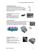
Page 6: ...ring actuated ball valve to shutoff ink when cartridges are removed Note ink is filtered at the cartridge only e Carriage Assembly Robust carriage bushing design thick bushings with 2 shims for better dimensional stability Bushings are secured by bushing retainers Bushings are grooved to minimize the effect of dirt and debris Cartridge doors secure and bias print heads into proper position One ste...

Page 7: ... hands cartridge maintenance through service station Cartridge cleaning or Vacuum prime feature Ink is deposited into a waste disposal bottle h Auto Clean Unit Door Magnet Suction pump motor used for priming ink lines Bottle full sensor IR Ink waste bottle Bottle present empty sensor I IR R ...

Page 8: ...ed Mode 2 pass 220 sfph 20 4 smph Productivity Mode 3 pass 150 sfph 14 smph Fine Mode 4 pass 115 sfph 10 7 smph Enhanced Mode 6 pass 75 sfph 7 0 smph 8 Pass Print Mode 58 sfph 5 39 smph 12 Pass Print Mode 37 sfph 3 44 smph High Quality 16 pass 26 sfph 2 8 smph 42 inch printer High Speed Mode 2 pass 195 sfph 18 1 smph Productivity Mode 3 pass 140 sfph 13 0 smph Fine Mode 4 pass 104 sfph 9 6 smph En...

Page 9: ...ackets Remove upper and lower shipping support brackets four bolts total and install appropriate stand leg to balance the printer Remove wing nut retaining bolt and 4 screws Step 2 Media System Installation 1 electrical connection When installing the right stand leg attach electrical plug connection to printer base ensure the plug is aligned straight and square onto the connector to prevent damage...

Page 10: ...l crossbar between stand legs and tighten four 4 securing screws Tighten the eight 8 stand leg screws after the crossbar has been properly installed Step 4 Auto Clean Unit System 2 electrical connections 1 tubing connection To attach the auto clean unit first connect the ink tube line to the pump nipple Attach both electrical plug connections to respective jacks Angle the assembly at a 45 degree a...

Page 11: ...the circuit beaker will pop out in an over current condition and will need to be replaced if this occurs Step 7 Reservoir Installation When installing the six 6 ink bottles ensure each bottle is installed straight up and down to avoid damaging pins at intermediate reservoir located at base Firmware Note C1 CL M1 ML Note wait 5 minutes prior to conducting line filling operation using Pump On from t...

Page 12: ...lity Menu Prime Menu Service Station Menu Pump On The fill process takes approximately 4 16 seconds per color When ink reaches the cartridge tube release the Pump On selection Repeat procedure for remaining colors NOTE To flush the ink system refer to Technical Bulletin 2 Only use the authorized Flush Kit part number 221984 00 to evacuate ink lines and clean the system of ink prior to printer tran...

Page 13: ...nal lines are smooth and clogged jets are not present If necessary perform Manual Jet Bypass for clogged or misfiring jets Select Utility Menu Calibration Menu Open Jet Menu Edit List Menu Scroll to particular jet number which has the clog problem and toggle off Select Ok to save selection NOTE A few streaks or lines may appear in the pre prime pattern area this is considered normal due to the uni...

Page 14: ...r Status The T1 and T2 temperature sensors will begin to slowly climb to the target temperature value i e 40 degrees C NOTE the new calibration menu structure is different from the previous firmware version please review the 3 calibration paths available B Activate the Line Length Test under Line Length Menu Utility Menu Calibration Menu Paper Calib Menu Line Length Menu Line Length Test using a d...

Page 15: ...o be assigned for the media type currently loaded Select Ok Example Assignments User 1 Photo Satin 180 g User 2 Premium Backlit 7 mil User 3 PP Gls 8 mil User 4 Rapid Dry Gls 190 g User 5 Photo Gls 160 g User 6 Water Res Vinyl A calibration complete message will be displayed on the control panel display Select Ok NOTE 1 do not select Select User or any previously entered data will be overwritten ...

Page 16: ...d off and on User Setting 1 is automatically initialized as a default operational setting Refer to NOTE 2 above to set the proper calibration value for the media type loaded If the incorrect user setting is used then banding in printed output may result due to the incorrect paper feed value being utilized Media Feed Adjust controls are better optimized and controlled from the Kodak 1200i software ...

Page 17: ...ate the Internal Test Print Select Utility Menu Service Menu Test Print This will help verify the printer calibrations are correct Inspect the vertical and horizontal alignment between all colors in the upper two sections of the test print If vertical or horizontal alignment is not achieved then repeat step D Step 12 Best Quality Mode To obtain the highest or optimum print quality mode from the pr...

Page 18: ...P IP protocol b Assign workstation IP address this address should be one number different or very close to from the printer s address for best results i e 192 168 24 73 Assign the Subnet mask and Default gateway address these addresses will match the printer DNS addresses are not required unless internet web access is going to be assigned and available 2 Assign IP address at printer i e 192 168 24...

Page 19: ...ter for direct connections or an RJ 45 Ethernet patch cable from HUB switch to printer if indirectly connected 4 At desktop right click on My Network Places again and select Properties At Local Area Connection window select Disable Then select Enable this will ensure the IP addressing has been refreshed sometimes required on Win 2000 XP systems ...

Page 20: ... correctly If the printer is not located perform steps 1 5 again NOTE Ensure Subnet mask and Default Gateway addresses are assigned and are the same at both the printer and the workstation c NOTE If steps a and b above are unsuccessful then install a standard TCP IP printer port driver and configure or assign an IP address to an existing NJ1000i Kodak 1200i printer driver or TCP IP port to match t...

Page 21: ...hould appear If REQUESTED TIME OUT messages appear then connectivity is incorrect verify steps 1 through 6 again 7 Assign IP address at RIP host workstation and set data type The IP address will be the same as the printer s IP address i e 192 168 24 74 Data type must be set to 9100 for proper data transfer to occur Pictured below is ONYX s printer port setup splash screen a port test may be activa...

Page 22: ...ect Software Utilities located EFPU utility and load Select port previously configured normally identified by a default IP address the first time loaded Select the printer test file link and open an xxxxxx rtl file from System CD images subfolder and select PRINT Printer should start printing within 30 seconds if sending pre ripped files to printer To download printer firmware product enhancements...

Page 23: ... 3 Bi 10 Kodak Production Glossy Poly Poster Plus 8 mil 10 Production 3 Bi 10 Kodak Production Satin Poly Poster Plus 8 mil 10 Production 3 Bi 10 Kodak Production Self Adhesive Glossy Poly Poster Plus 6 mil 10 Production 3 Bi 10 Kodak Production Self Adhesive Satin Poly Poster Plus 6 mil 10 Production 3 Bi 10 Kodak Self Adhesive Glossy Poly Poster 120g 10 Production 3 Bi 10 Kodak Self Adhesive Mat...

Page 24: ...10 Vinyl Banners Kodak Water Resistant Removable Vinyl 6 mil 2 User Defined 8 Bi 10 Kodak GO Water Resistant Self Adhesive Vinyl 6 mil 2 Enhanced 6 Bi 10 Kodak Water Resistant Scrim Banner 17 mil 6 Enhanced 6 Bi 10 Kodak Water Resistant Poly Poster Matte 8 mil 2 Enhanced 6 Bi 10 Kodak Water Resistant Self Adhesive Poly Poster Matte 9 mil 2 Enhanced 6 Bi 10 Canvas Kodak Artists Semigloss Canvas 20 ...

Page 25: ...ium White Film 5 mil Yes Yes Yes Yes Reverse Print Backlit VS 5 mil No No Yes Yes Kodak Poly Poster Glossy 7 mil No No No Yes Kodak Poly Poster Satin 7 mil No No No Yes Indoor Outdoor Kodak Reverse Print Backlit Film 6 mil Yes No No Yes Kodak Water Resistant Backlit Film 8 mil Yes No Yes Yes Kodak Water Resistant Poly Poster Matte 8 mil Yes Yes Yes Yes Kodak Water Resistant Self Adhesive Poly Post...

Page 26: ...k Water Resistant Poly Poster Matte 8mil Yes Yes Yes Yes Kodak Water Resistant Self Adhesive Poly Poster Matte 9 mil Yes Yes Yes Yes Vinyl Kodak GO Water Resistant Scrim Vinyl No NA NA Yes Kodak GO Water Resistant Self Adhesive Vinyl No Yes Yes Yes KODAK Water Resistant Removable Vinyl No Yes Yes Yes KODAK Water Resistant Scrim Banner No No No Yes Specialty Fine Art Kodak Artists Semigloss Canvas ...

Page 27: ...media head strike onto the Y Arm directly above the left and right edges of the media surface NOTE illustrated in yellow below parts are actually black or white in color NOTE After loading media a friendly reminder control panel message Warning Adjust Rear Paper Guides will appear Ensure both rear paper guides are not touching media edges 2 mm offset minimum on both sides This is very important as...

Page 28: ...Modes To activate the drying system select Setup Menu Dryer Menu Scroll through available selections 12 dryer modes are available refer to dryer matrix label affixed to printer s top cover or Installation Step 14 above for specific modes of operation 0 OFF 1 Fans Only 2 Minimum Fans On 3 Minimum 4 Heat Low Fans On 5 Heat Low 6 Heat Medium Fans On 7 Heat Medium 8 Heat High Fans On 9 Heat High 10 Ma...

Page 29: ...d by maintaining proper temperature and humidity levels RH in both storage and operational areas The use of humidifiers will add water to the air resulting in a humidity level increase This will help prevent normal heating season problems caused by dry air General Environmental Conditions Controlling the print location and surrounding humidity is key toward maintaining good color output no matter ...

Page 30: ...he software installation instructions or directly at the printer under Setup Menu Network Menu 2 Client Installation one per workstation Install the Client Installation package onto additional workstations that will be printing to the printer in addition to the server workstation Note the database program MSDE should only be installed onto the primary server workstation one subnet per server NOTE ...

Page 31: ...ill likely get dirty between 500 700 plot hours and will need to be cleaned as well periodically or image shift may be observed see sample problem below Spray sensor surfaces with Windex solution or use small tipped swab and blow dry with canned air Refer to Technical Bulletin 3 for more detailed cleaning instructions and cleaning kit ordering B Cleaning of the following subassemblies is suggested...

Page 32: ...r Groove cotton swab dampened with NovaKlean solution 3 Flex Driver Cables towel dampened with NovaKlean isopropyl alcohol D Clean the following items as required 1 Cartridge lint free towel dampened with NovaKlean solution and or isopropyl alcohol 2 Auto Clean Unit Disposal Bottle prompted by Empty Waste Bottle Now control panel software suite message dispose of ink in accordance with regional gu...

Page 33: ... free towel dampened with NovaKlean solution clean behind Magenta flex driver cable perform second cleaning with isopropyl alcohol E Replace the following item as required 1 Cutter when smooth cuts are no longer observed when media is cut or if Internal Shutdown Carriage Axis Failures occur and are determined to be caused by the cutter assembly ...

Page 34: ...000 plot hours or when vertical banding or Carriage Axis Errors are observed bushing will typically last between 630 and 2200 plot hours depending on the print environment conditions cleanliness and type of actual printing performed 2 Replace the service station every 2000 plot hours station wipers may require frequent replacement depending on customer maintenance 3 Replace the idler frame tension...

Page 35: ...e Available partial 05 24 2005 None Technical Bulletin 3 Encoder Strip and Encoder Sensor Cleaning Video Procedure Available 05 24 2005 None Technical Bulletin 4 Print and Lamination Guidelines Video Procedure Available partial 05 24 2005 TB1 Technical Bulletin 5 Tiling Guidelines Video Procedure Available partial 05 24 2005 TB1 and 4 Technical Bulletin 6 Printer Networking 08 22 2005 None Technic...

Page 36: ... errors or insufficient ink delivery Type 1 ID chip communication errors Example Pen Error Code 4 This type of error is identified by a special code and it usually indicates there is a fault or bad connection with the ID chip The suggested course of action is to inspect the ID chip and its connection to make sure the chip is making contact Try reseating the cartridge if no problems are detected yo...

Page 37: ...erature exceeding a set maximum value This is generally an indication that ink is not being fed to the jet plate area to keep it cool while printing An insufficient factory prime leaking cartridge typically observed with a new cartridge that has leaked into the cartridge foil packaging or an ink delivery system problem blockage or leakage can be the cause of observing this error Typically the cart...

Page 38: ...CE STATION MENU Simultaneously depress VACUUM PRIME and PUMP ON at the same time and release you should hear the auto clean unit sucking air c Gently move the carriage over the service station manually push over with one hand gently push down on top of carriage to ensure you have good contact suction Allow pump to engage cartridges for at least 10 15 seconds Select Exit at menu to stop pump action...

Page 39: ...idge must be replaced This error is often the result of not correcting a MAX INK TEMP EXCEEDED error as described in Example 1 above All OVERCURRENT cartridge errors require replacement of the cartridge and recycling of the printer power The steps involved to restart the printer and replace the cartridge are 1 cancel the print job at the host 2 press the MORE INFO key on the keypad display to show...

Page 40: ...ycle are 1 cancel the print job at the host 2 navigate to the keypad main menu and press RESET 3 navigate to the alarm display by pressing ALARM 4 press the MORE INFO key 5 determine the problem cartridge 6 access carriage and replace the problem cartridge 7 access carriage back to home position 8 send a new print job to clear the alarm a prime printing test or calibration plot will clear the alar...

Page 41: ...nsate at a higher pass mode Select YES to give permission to proceed to this new higher pass mode or select NO to stay at the current pass mode One line of the display will show the cartridge colors with the problem cartridge s flashing PEN ERROR JOB PAUSED This pen alarm provides the top level error status only Additional information about the specific error is available if the operator presses t...

Page 42: ...place appropriate flex driver cable Replace trailing cable Replace carriage board defective jack connector If the Pen Error is related to an ID chip communication failure the error message format changes to the following color Pen Error Code ranges from 2 to 7 Where 2 color Pen Error Pri CRC Failed 3 color Pen Error Sec CRC Failed 4 color Pen Error No Response 5 color Pen Error Write Protected 6 c...

Page 43: ...nk types color BOTTLE ERROR INVALID OEM ID Translation The bottle OEM ID does not match the main board OEM ID color INK BOTTLE ERROR CODE 7 Translation This message is an indication that the ID chip affixed to the bottle is not working properly incorrect programming etc color BOTTLE ERROR INVALID CHIP ID Translation This message is an indication the chip is the incorrect OEM version i e Encad 1 ve...

Page 44: ...a print job If an error occurs during a print job the user has 30 seconds to find a replacement bottle and swap out the identified stall before the print job is automatically paused Note if a bottle is missing a bottle error will occur but if a bottle is missing bottle chip is missing or bottle chip is not making contact with the ID housing within intermediate reservoir then an alarm condition wil...

Page 45: ...the intermediate reservoir appears to be more than 60 full above the reservoirs 30 ml level this error should not be displayed The intermediate reservoir has a 52 ml capacity color JOB PAUSED INK RESERVOIR EMPTY Message normally appears after 10 ml ink buffer has been used refill bottle was not replaced in time occurs between 10 and 30 minutes following the INK RESERVOIR LOW error message NOTE Thi...

Page 46: ...vity 3 Swap the suspect reservoir data board with either the black or cyan reservoir data boards to verify functionality Replace data board with a new one NOTE only replace the reservoir data board see picture prior to replacing any other assembly 4 Replace ink reservoir wiring harness if a wiring harness plug is suspected as defective 5 Check main board by replacing with spare ...

Page 47: ... The icon will also be displayed to show the alarm condition is active Error condition will continue to be reported when dryer is switched to Off or Fans Only Dryer Sensor Fault error will not be displayed if both sensors are faulty If both sensors are faulty the error Dryer System Fault Dryer Off will be displayed see DRYER SYSTEM FAULT DRYER OFF below Action Contact technical support DRYER SYSTE...

Page 48: ...r will operate normally but may give intermittent OverTemp errors or pop the circuit breaker adjacent to switch NOTE Since the dryer is turned off automatically the error condition may disappear as soon as the alarm is displayed Action Contact technical support DRYER WARMING UP PRINT ANYWAY Error condition occurs and sounds a beep when a print job is processed and the current nose dryer temperatur...

Page 49: ...event premature failures Refer to routine maintenance 2 A dirty or defective encoder strip or encoder sensor may cause a CAE or the following print symptoms see photos notice the large bands image skewing and data shift at right side to occur prior the CARRIAGE AXIS FAILURE The problem may also be caused by an unseated memory module or improper grounding leading to electrostatic discharge ESD inte...

Page 50: ...ifferent from No 2 above 5 If a CAE occurs and ink is observed around the service station area ink is spitting up through the service station and onto the carriage assembly at right side of printer the auto clean unit may be defective Contact technical support NOTE The encoder strip encoder sensor and carriage paper sensor should be cleaned or errors may continue to occur To clean the encoder stri...

Page 51: ... Feeder Stop is the default and will pause printing when the printer cannot unwind enough media to block the leg sensor This feature is very handy while printing unattended especially if the end of media is securely taped to the roll The user can press Pause to continue printing but the alarm will remain until new roll of media is loaded CAUTION When set to Normal this stop feature is disabled and...

Page 52: ...D chip or its connection is faulty There is one more unique MBID error that can occur This error will be displayed only if there is an invalid OEM byte sent to the main board chip at initialization time The OEM field is read from the ID chip 1 Kodak 1200i 4 POS 5 Special 6 Xerox 8142 8160 MBID ERROR INVALID OEM ID In this instance the manufacturer is required to change the OEM designation to an ap...

Page 53: ...ing The front paper guides should be verified as well NOTE Always ensure the rear media edge guides are spaced at least 1 2 mm away from the media edges following a media load the media should not be in contact with the guide or media drag may occur and possibly cause left or right side banding Refer to Service Bulletin 1 for complete media load instructions CARRIAGE FPGA ERROR Error Normally this...

Page 54: ...l Training Guide 54 CARRIAGE PAPER SENSOR IS UNSTABLE This usually indicates the carriage paper sensor is defective or unplugged Reseat and or replace the carriage paper sensor NOTE only authorized service providers should perform this repair action ...

Page 55: ...ge The installer should always validate the power and grounding scheme at the installation facility A second issue would be the lack of electrostatic discharge ESD protection Without proper grounding the ESD brushes are rendered useless A higher incidence of cartridge failures will occur if adequate grounding not properly supplied as well as possible malfunctions of printer s electronic circuitry ...

Page 56: ...tern are incorrectly spaced i e two lines are closer together while one line is spread farther from the other two or may be printed outside of the calibration box area Feed adjust values may be too low i e 4840 to 4870 Typical feed adjust paper calib values should be 4800 15 for most media types Media which generates a high amount of static electricity i e 15 000 30 000 volts and is thin i e 3 mil...

Page 57: ... Premature Cartridge Failure 700 ml Massive cartridge jet failures may occur prior to the standard cartridge warranty 700 ml Static interference and electrical discharges from media printer to the cartridge jet plates can cause premature failure of internal cartridge electronics B ESD Control Measures 1 Proper Power Cord Grounding Only use the approved power cord for the specific region as supplie...

Page 58: ...re range is 68 72 degree F 20 22 2 degrees C 3 Ant Static Mats The installation of Anti Static mats below the printer have been known to help control ESD levels in the space on and around the printer 3 Air Plenum Grounding In low humidity environments static build up can occur across the air plenum and generate ESD levels which may interfere with printed output mainly during dryer operations if th...

Page 59: ... receptacle power and adequate grounding Below are some suggested test methods for both the printer and the incoming power source CAUTION Only properly trained service technicians should attempt to perform any of the steps below It is strongly suggested to contact a certified electrician if a test method or measured value is not completely understood 1 Testing AC level on printer chassis Turn on P...

Page 60: ...ied electrician will need to be contacted to upgrade the electrical system with a properly grounded outlet Also do not work on printer if a 3 prong to 2 prong adapter non grounded standard receptacle non grounded GFCI receptacle or a separate ground line runs from the printer Contact technical support management if necessary for intervention assistance 3 Testing Receptacle Neutral to Ground Voltag...

Page 61: ...stomer a certified electrician will need to be contacted to upgrade the electrical system with a properly grounded outlet or to correct a neutral to ground voltage problem D Power Voltage Testers 1 In North America basic receptacle testers are available for testing standard 110 volt receptacle wall outlets for proper polarity and ground detection These models are probably the fastest way in detect...

Page 62: ...stance transforms these currents into voltage fluctuations As a consequence of ground loop induced voltages the ground reference in the system is no longer a stable potential so signals ride on the noise The noise becomes part of the program signal Ground loop is a common wiring condition where a ground current may take more than one path to return to the grounding electrode at the service panel A...

Page 63: ...nly dangerous to the operator but will likely result in imaging output problems Some customers install line adapters which have a ground lead then attach a wire between the ground lead and the receptacle box housing i e screw or other fixed point CAUTION Installation of these types of adapters provides an extremely unreliable ground is dangerous to the operator and equipment and should never be co...

Page 64: ...image edges combined with an image shift then this problem is typically a dirty encoder strip or dirty encoder sensor Please refer to Technical Bulletin 5 for proper cleaning procedures DISCLAIMER This document has been provided as an aid to assist the installer technician authorized service provider or electrician in solving a very specific issue regarding grounding related problems on the Kodak ...

Reviews: