background image

WENAM00150

HYDRAULIC EXCAVATOR

PC30MR-

5

PC30MR-5

Operation &
Maintenance Manual

SERIAL NUMBERS

ORIGINAL INSTRUCTIONS

Unsafe  use  of  this  machine  may  cause  serious
injury  or  death.  Operators  and  maintenance
personnel must read this manual before operating
or maintaining this machine. This manual should
be kept inside the cab for reference and periodically
reviewed  by  all  personnel  whowill  come  into
contact with the machine.

WARNING

F50001 

and up

F50001 

and up

PC35MR-

5

PC35MR-5

Summary of Contents for PC30MR-5

Page 1: ...is machine may cause serious injury or death Operators and maintenance personnel must read this manual before operating or maintaining this machine This manual should bekeptinsidethecabforreferenceandperiodically reviewed by all personnel whowill come into contactwiththemachine WARNING F50001 and up F50001 and up PC35MR 5 PC35MR 5 ...

Page 2: ......

Page 3: ... new Komatsu or Ko matsu approved rebuilt parts or assemblies or others parts of equivalent quality and that the engine be serviced by an authorized Komatsu distribu tor Failure to follow these recommendations could result in ineffective serv ice damage to the product or safety risks including personal injury or death 1 1 WENAM00150 ...

Page 4: ...e oper ator s seat If this manual is lost or damaged contact Komatsu or your Komatsu distributor and tell them about the machine model name and the serial No immediately to arrange for its replacement For details regarding the machine model name and the serial No see the machine serial No plate In order to arrange the proper Operation and Maintenance Manual you will need to provide the machine mod...

Page 5: ...ty mes sage This signal word indicates an imminently hazardous situation which if not avoided will result in death or serious injury This signal word indicates a potentially hazardous situation which if not avoided could result in death or serious injury This signal word indicates a potentially hazardous situation which if not avoided may result in minor or moderate injury It may also be used to a...

Page 6: ...azardous condition is shown inside a circle Komatsu cannot predict every circumstance that might involve a potential hazard in operation and maintenance Therefore the safety messages in this manual and on the machine may not include all possible safety precautions If any procedures or actions not specifically recommended or allowed in this manual are used it is your responsibility to take the nece...

Page 7: ...tandard deviation of the meas ured time averaged A weighted emission sound pressure level at the operator s position is 2 5dB in accordance with ISO 11201 Sound power level emitted by the machine measured ac cording to ISO 6395 Dynamic test method simulated working cycle This is the guaranteed value as specified in European di rective 2000 14 EC This value includes an uncertainty of 0 8dB ISO 6396...

Page 8: ...lling in good condition Remove any large rocks or obstacles Fill any ditches and holes Site manager should provide machine operators with machine and schedule time to maintain terrain conditions 4 Use a seat that meets ISO 7096 and keep the seat maintained and adjusted Adjust the seat and suspension for the weight and size of the operator Wear seat belt Inspect and maintain the seat suspension and...

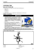
Page 9: ...k up transport and distribute component parts of buildings or civil engineering structures This machine is not prepared for use in Demolition Using this machine in demolition work gives an in creased risk of serious injury or death All Komatsu machines that are specifically designed and can be used for demolition work will display the Komatsu demolition decal If the machine does not display this d...

Page 10: ...rom outside the machine and 1 0 m above the ground except of the right side which is 1 2 m above the ground 12 m circumference visibility The figure below shows a visibility from the machine for a circumference of 12 m Shaded areas A and B in the figure show areas the views of which are blocked when the machine is equipped with the mirrors and other visibility assistant devices Be fully aware that...

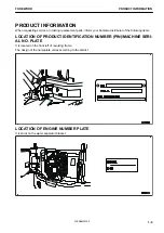
Page 11: ...ollowing items LOCATION OF PRODUCT IDENTIFICATION NUMBER PIN MACHINE SERI AL NO PLATE It is located on the front left of revolving frame The design of the nameplate varies according to the district LOCATION OF ENGINE NUMBER PLATE It is stuck on the water separator bracket FOREWORD PRODUCT INFORMATION 1 9 WENAM00150 ...

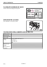
Page 12: ...RS AND DISTRIBUTOR Machine serial No Engine serial No Product identification number PIN Manufacturers name Address Komatsu Italia Manufacturing S p A Via Atheste 4 35042 Este PD Italy Distributor name Address Service Personnel Phone Fax Product contains fluorinated greenhouse gases HFC 134a GWP 1430 CO2 eq 1 00 t 0 7 kg PRODUCT INFORMATION FOREWORD 1 10 WENAM00150 ...

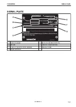
Page 13: ...SERIAL PLATE A SERIAL NUMBER E MACHINE DESIGNATION TYPE B WEIGHT F YEAR OF CONSTRUCTION C PRODUCT IDENTIFICATION NUMBER G ENGINE POWER D MANUFACTURER FOREWORD SERIAL PLATE 1 11 WENAM00150 ...

Page 14: ...hat this machines PC30MR 5 PC35MR 5 Fulfils all the relevant provisions of following EC Directives Machine Directive 2006 42 EC Electro Magnetic Compatibility Directive 2014 30 EU Outdoor Noise Directive 2000 14 EC amended by 2005 88 EC Radio Equipment Directive 2014 53 EU DECLARATION OF CONFORMITY FOREWORD 1 12 WENAM00150 ...

Page 15: ...PREVENT FIRE 2 18 PRECAUTIONS WHEN GETTING ON OR OFF MACHINE 2 19 DO NOT GET CAUGHT IN WORK EQUIPMENT 2 22 PRECAUTIONS RELATED TO PROTECTIVE STRUCTURES 2 22 PROTECTION AGAINST FALLING FLYING OR INTRUDING OBJECTS 2 23 UNAUTHORIZED MODIFICATION 2 23 PRECAUTIONS RELATED TO ATTACHMENTS AND OPTIONS 2 23 PRECAUTIONS RELATED TO CAB GLASS 2 23 PRECAUTIONS WHEN RUNNING ENGINE INSIDE BUILDING 2 24 PRECAUTIO...

Page 16: ... ROAD LINERS SHOES 3 161 COMPARISON OF RUBBER ROAD LINERS SHOES AND STEEL SHOES 3 161 WARRANTY OF RUBBER AND ROAD LINERS SHOES 3 161 PROHIBITED OPERATIONS WHEN USING RUBBER AND ROAD LINERS SHOES 3 161 PRECAUTIONS FOR USING RUBBER AND ROAD LINERS SHOES 3 162 TRANSPORTATION 3 165 PRECAUTIONS FOR TRANSPORTING MACHINE 3 165 SELECT TRANSPORTATION METHOD 3 165 LOADING AND UNLOADING WITH TRAILER 3 166 ME...

Page 17: ...TARTING 4 41 EVERY 100 HOURS MAINTENANCE 4 41 EVERY 250 HOURS MAINTENANCE 4 44 EVERY 500 HOURS MAINTENANCE 4 45 EVERY 1000 HOURS MAINTENANCE 4 54 EVERY 1500 HOURS MAINTENANCE 4 57 EVERY 2000 HOURS MAINTENANCE 4 57 EVERY 4000 HOURS MAINTENANCE 4 66 SPECIFICATIONS 5 1 SPECIFICATIONS 5 2 SPECIFICATIONS PC30MR 5 5 2 SPECIFICATIONS PC35MR 5 5 4 EXPLANATION OF LIFT CAPACITY CHART 5 6 ATTACHMENTS AND OPT...

Page 18: ...ENT 6 24 RECOMMENDED ATTACHMENT OPERATIONS 6 26 HYDRAULIC BREAKER 6 26 REPLACEMENT PARTS 7 1 PERIODIC REPLACEMENT OF DEFINED LIFE PARTS 7 2 DEFINED LIFE PARTS LIST 7 2 CONSUMABLE PARTS 7 3 CONSUMABLE PARTS LIST 7 3 RECOMMENDED FUEL COOLANT AND LUBRICANT 7 4 LUBRICATION CHART 7 4 METHOD FOR USING FUEL COOLANT AND LUBRICANTS ACCORDING TO AMBIENT TEMPERA TURE 7 6 RECOMMENDED BRANDS AND QUALITIES OTHE...

Page 19: ...ad and make sure that you fully understand the precautions descri bed in this manual and the safety labels on the machine When operating or servicing the machine always follow these precautions strictly 2 1 WENAM00150 ...

Page 20: ...hen cleaning the safety labels do not use organic solvents or gasoline These may cause the labels to peel off If the safety labels are damaged lost or cannot be read properly replace them with new ones For details of the part numbers for the safety labels see this manual or the actual label and place an order to your Komatsu distributor There are also other labels in addition to the warning signs ...

Page 21: ...ension 6 Danger do not enter within swing range 7 Caution stop rotation during inspection and mainte nance 8 Caution for high temperature coolant and hydraulic oil 9 Warning for operation inspection and maintenance 10 Caution for handling cable 11 Caution for handling battery 12 Caution when closing floor 13 Caution do not start by short circuiting 14 Quick release battery terminal 16 Warning when...

Page 22: ... Warning for handling ROPS 25 Control levers operational function diagram 26 Control levers operational function diagram 27 Switches operational function diagram 28 Lifting and fastening decals for transport 29 Lifting capacities diagram 30 Caution for overload machine LOCATION OF SAFETY LABELS CAB SPEC RKA63720 SAFETY LABELS SAFETY 2 4 WENAM00150 ...

Page 23: ...3 Caution do not start by short circuiting 14 Quick release battery terminal 15 Caution when stowing front window 16 Warning when reversing 17 Warning against high voltage cable 18 Caution when standing in operator s cab 19 Caution for blast jobsite 20 Warning for quick coupler system 21 Warning always fasten safety belt 22 Warning when leaving operator s seat 23 Emergency escape 24 Warning for ha...

Page 24: ...tion 2 Caution for handling accumulator and gas spring 09659 A057B There is a hazard of explosion causing injury Do not disassemble the accumulator make holes in it weld it cut it roll it or bring it near a flame 3 Notice for lock floor unit 22L 98 22180 4 Caution when opening floor 22N 98 53710 Insert a lock pin to keep tilted floor in a safe position 22L 98 22180 22N 98 53710 SAFETY LABELS SAFET...

Page 25: ...proper handling 6 Danger do not enter within swing range 22N 98 51740 There is a danger of getting caught when upper structure swings Do not enter range of swing 7 Caution stop rotation during inspection and maintenance 09667 A0481 Sign indicates a hazard of rotating parts such as belt fan etc Turn off before inspection and maintenance 22N 98 51740 SAFETY SAFETY LABELS 2 7 WENAM00150 ...

Page 26: ...remove the radiator cap or hydraulic tank oil filler cap when cooling water or hydraulic oil is at high tempera ture 9 Warning for operation inspection and maintenance 09651 A0481 Read the manual before operating inspection maintenance disassembly assembly and transportation 10 Caution for handling cable 09808 A0881 Sign indicates an electric hazard from handling the cable Read manual for safe and...

Page 27: ...664 60001 a Never smoke or use any naked flame near the batteries no sparks b Always wear safety glasses when working with batteries c Keep children away from batteries d Caution battery acid KS000327 SAFETY SAFETY LABELS 2 9 WENAM00150 ...

Page 28: ...4 K0481 There is danger of being caught between the frame or oth er moving parts and suffering injury Do not put your hands or feet between movable parts where they may become caught 13 Caution do not start by short circuiting 09842 A0362 Prohibition of short circuit start 09842 A0362 SAFETY LABELS SAFETY 2 10 WENAM00150 ...

Page 29: ... horn to alert people nearby Be sure no one is on or near machine or in swing area Rotate cab for full view of travel path if it can be done safe ly Use spotter if view is obstructed k k WARNING To open or close the front or ceiling window never stand up from the operator s seat before throwing the safety lock lever to the lock position Inadvertently touching any of the working equipment control l...

Page 30: ... up from the operator s seat such as when opening or closing the front window or when removing or installing the bottom window or when adjusting the opera tor s seat always lower the work equipment completely to the ground set lock lever 1 securely to the LOCK position L then stop the engine If you accidentally touch the con trol levers pedals when they are not locked there is a hazard that the ma...

Page 31: ...20 Warning for quick coupler system Cab spec 22N 98 53830 There is a danger of an exposed person being killed by falling attachment Read the manual for safe operation 21 Warning always fasten safety belt 09848 A0480 If the machine tipping the operator may be thrown out of the operator s seat Always fasten the safety belt Read the manual for more detail SAFETY SAFETY LABELS 2 13 WENAM00150 ...

Page 32: ... or death 23 Emergency escape Cab spec 09844 00050 24 Warning for handling ROPS 22N 98 53760 09620 A3001 If any modification is applied to the ROPS it may affect the strength and may not comply with the standard ROPS may provide less protection if it has been structural ly damaged or involved in roll over Always wear seat belt when moving 25 Control levers operational function diagram 09822 A0751 ...

Page 33: ...Canopy spec 22F 98 51430 27 Switches operational function diagram 1 attachment Canopy spec 22F 98 32930 Cab spec 22F 98 32960 2 attachment 22F 98 32991 SAFETY SAFETY LABELS 2 15 WENAM00150 ...

Page 34: ... arm 22F 98 52550 Long arm 22F 98 52570 Quick coupler and 3rd line attachment 22F 98 R2550 For details see SPECIFICATIONS EXPLANATION OF LIFT CAPACITY CHART 30 Caution for overload machine Do not exceed the specified lifting load PC30MR 5 Standard arm 22L 98 52780 Long arm 22L 98 52790 PC35MR 5 Standard arm 22F 98 52780 Long arm 22F 98 52790 Quick coupler and 3rd line attachment 22F 98 R2780 For d...

Page 35: ...ECAUTIONS FOR SAFETY RELATED EQUIPMENT Be sure that all the protective guards covers and mirrors are installed properly If any of them are broken replace it immediately Understand the using method of the safety related devices and use them properly Never remove any safety related devices Always keep them in good operating condition INSPECT MACHINE Check the machine before starting operations If an...

Page 36: ...the following precautions to prepare for action if any serious personal injury or death or fire should occur Be sure that fire extinguishers have been provided and read the labels to ensure that you know how to use them for the possibility of fires Perform periodic inspection and maintenance to ensure that the fire extinguisher can always be used Provide a first aid kit in the storage point Perfor...

Page 37: ...starting Fire caused by accumulation of combustible material Remove any dry leaves chips pieces of paper coal dust or any other combustible materials accumulated or affixed around the engine exhaust manifold muffler or battery or inside the undercovers Fire coming from electric wiring Short circuits in the electrical system can cause fire Always observe the following Keep all the electric wiring c...

Page 38: ...hen getting on or off the machine Never climb on the engine hood or covers where there are no non slip pads Do not get on or off the machine with tools in your hand NO JUMPING ON OR OFF MACHINE Getting on or off the moving machine can cause serious personal injury or death Always observe the following Never jump on or off the machine Never get on or off a moving machine If the machine starts to mo...

Page 39: ...stop the engine In addition lock all places and always take the key with you and keep it in the specified location EMERGENCY EXIT FROM OPERATOR S CAB If it should be impossible to open the door of the cab break the window glass with the hammer supplied and use the window as an emergency escape When escaping remove the pieces of glass from the window frame first and be careful not to cut yourself o...

Page 40: ...ways observe the follow ing If the machine is equipped with a protective structure do not remove the protective structure and perform operations without it If the protective structure is welded or holes are drilled in it or it is modified in any other way its strength may drop Any modification is prohibited If the protective structure is damaged or deformed by falling objects or by rolling over it...

Page 41: ...reate hazards Before making a modifica tion consult your Komatsu distributor PRECAUTIONS RELATED TO ATTACHMENTS AND OPTIONS Any personal injuries product failures physical loss or damage or influence on the environment resulting from the use of unauthorized attachments or parts will not be the responsibility of Komatsu When installing optional parts or attachments contact your Komatsu distributor ...

Page 42: ...entilation If the engine or ma chine must be operated inside a building or underground where the ventilation is poor take steps to ensure that the en gine exhaust gas is removed and that ample fresh air is brought in When handling the fuel cleaning oil and paint work in a well ventilated area with windows and doors open GENERAL PRECAUTIONS COMMON TO OPERATION AND MAINTE NANCE SAFETY 2 24 WENAM0015...

Page 43: ...AUTIONS WHEN WORKING ON LOOSE GROUND Avoid driving or operating the machine near the edge of cliffs road edges and deep ditches The ground may be weak in such areas If the ground should collapse under the weight or vibration of the machine there is a hazard that the machine may fall or tip over Remember that the soil is weak in these areas after heavy rain or blasting or after earthquakes When wor...

Page 44: ...rk places turn on the working lamp and headlamps installed to the machine and set up additional lighting in the work area if necessary Stop operations if the visibility is poor because of mist snow rain or dust When checking the mirrors installed to the machine remove all dirt and adjust the angle of the mirror to ensure good visibility CHECK SIGNS AND SIGNALMAN S SIGNALS If signals and labels are...

Page 45: ...s to ensure a good view Be sure to perform thorough walk around check Remove all dirt from the surface of the lens of the headlamps and working lamps and check that they light up correctly Check the coolant level fuel level and oil level in engine oil pan check for clogging of the air cleaner and check for damage to the electric wiring Check that there is no mud or dust accumulated around the mova...

Page 46: ...tarting the engine by using the jumper cables When connecting a normal machine to a failed machine with the jumper cables always use the normal machine with the same battery voltage as the failed machine When starting the engine with the jumper cables perform the starting operation with 2 workers one worker sitting in the operator s seat and the other working with the battery When starting from an...

Page 47: ...erious injury or death Always lock all the doors and windows of the operator s compartment in position regardless of whether it is open or closed Always close all the windows and doors on jobsites where there is danger of scattering fragments and things which may intrude into operator s cab Prohibit anyone other than the operator to get on the machine If there are any people in the area around the...

Page 48: ...operate the steering suddenly There is a danger that the machine may tip over The work equip ment may hit the ground and the machine may lose its balance or it may damage the machine or structures in the area When using the machine to prevent serious personal injury or death caused by the work equipment or by the machine tipping over due to overloading do not use the machine beyond the permitted p...

Page 49: ...e it at low speed When driving the machine downhill lower the engine speed keep the travel lever close to NEUTRAL position and drive it at low speed When driving the machine down the steep hills of 15 or more set the sprocket side downward and drive with low er engine speed in the posture shown in the figure Always drive the machine straight up or down a slope Driving the machine at an angle or ac...

Page 50: ...ill side when the bucket is loaded This opera tion is dangerous and may cause the machine to turn over If the machine has to be used on a slope pile the soil to make a platform A that will keep the machine as horizon tal as possible Do not work on a slope covered with the steel plates Even with slight slopes there is a hazard that the machine may slip PROHIBITED OPERATIONS If the machine turns ove...

Page 51: ...ct the boom cylinder It is dangerous that the machine may tip over by the impact In the operation using the fork or grapple do not attempt to pick up an object with the tips The picked up object can easily slip off Machine may be damaged or personal injury or death may occur PRECAUTIONS WHEN OPERATING ON SNOW OR FROZEN SURFACES Snow covered or frozen surfaces are slippery so be extremely careful w...

Page 52: ...Always observe the following Always check the machine dimensions carefully Depending on the work equipment and optional devices installed the machine weight transportation height and overall length differ Check beforehand that all bridges and other structures on the transportation route are strong enough to withstand the combined weight of the transporter and the machine being transported This mac...

Page 53: ...r the work equipment retract it and per form the operation slowly For machines equipped with a cab always lock the door after loading the machine To prevent the door from opening during transportation When the handrail is required to be removed be careful not to lose it When reinstalling the handrail be sure to install it securely TOWING AND BEING TOWED PRECAUTIONS FOR TOWING AND BEING TOWED Alway...

Page 54: ...pped with safety valves and an overload alarm in compliance with EN 474 5 PRECAUTIONS FOR LIFTING OPERATIONS Falling of a lifted load or tipping over of the machine can cause serious personal injury or death Always observe the following Determine the signals to be used and place a signalman in position Do not perform lifting work on slopes soft ground or other places where the machine is not stabl...

Page 55: ...ure Always be sure to lift within the relevant lifting limits and not exceed ing RLL Do not use the work equipment or swing to pull the load in any direction There is a danger that the lifting eye may be damaged due to abnormal loading making it unsafe to lift Where possible the lifting operation should be carried out with the bucket curled in order to increase visibility and prevent any obstructi...

Page 56: ... is to be lifted at a height where this is not possi ble the sling or chain must only be guided by the back wall of the bucket and not any other part of the machine PRECAUTIONS FOR OPERATION SAFETY 2 38 WENAM00150 ...

Page 57: ...he tidy to enable you to perform operations safely If the work place is not kept clean and tidy there is the danger that you will trip slip or fall over and injure your self SELECT SUITABLE PLACE FOR INSPECTION AND MAINTENANCE Stop the machine on a firm level ground Select a place where there is no hazard of landslides falling rocks or flooding ONLY AUTHORIZED PERSONNEL As long as maintenance of t...

Page 58: ...d Block the tracks from movement PRECAUTIONS FOR OPENING AND CLOSING FLOOR Do not open the floor on the slope ground or in windy weather otherwise it may lead to serious personal injury or death Do not open the floor when the engine is running the door if the machine is equipped with the cab is open or the lock lever is in Free position otherwise it may lead to seri ous personal injury or death Im...

Page 59: ...ssary to operate the control levers or pedals always give a signal to your fellow workers to evacuate them to a safe place PRECAUTIONS WHEN INSTALLING REMOVING OR STORING ATTACHMENTS Appoint a leader before starting removal or installation operations for attachments Place attachments that have been removed from the ma chine in a stable condition so that they do not fall And take steps to prevent u...

Page 60: ...e machine will suddenly fall Never work under the work equipment or the machine If it is necessary to raise the work equipment or the ma chine and then go under it to perform inspection or mainte nance support the work equipment and machine securely with blocks and stands strong enough to support the weight of the work equipment and machine If the work equipment and machine are not supported they ...

Page 61: ...ine take it to a well ventilated place remove the battery caps then perform the charging After charging tighten the battery caps securely Danger from dilute sulphuric acid When the battery is being charged flammable hydrogen gas is generated and may explode In addition the battery electrolyte includes dilute sulphuric acid Any mistake in handling may cause serious personal injury explosion or fire...

Page 62: ...iling water or steam spurting out when checking or draining the coolant wait for the coolant to cool down to a temperature where the radiator cap can be touched by hand Then loosen the cap slowly to release the pressure in side the radiator and remove the cap PRECAUTIONS FOR HIGH TEMPERATURE OIL To prevent burns from hot oil spurting out or from touching high temperature parts when checking or dra...

Page 63: ... pressure hoses or piping it may cause fire or defective operation It is dangerous and may cause serious personal injury or death If the hose or piping mounts are loose or oil or fuel is found to be leaking from the mount stop operations and tighten to the specified torque If any damaged or deformed hoses or piping are found consult your Komatsu distributor Replace the hose if any of the following...

Page 64: ...pring that acts to reduce the impact on the idler If it is disassembled by mistake the spring may shoot out and cause serious personal injury or death If it is necessary to disassemble it ask your Komatsu distributor to perform the work HANDLE ACCUMULATOR AND GAS SPRING This machine is equipped with an accumulator Even after the engine stops if the work equipment control lever is operated after st...

Page 65: ...rmful objects such as oil fuel coolant solvent filters and batteries Avoid exposure to burning rubber or plastics which produce a toxic gas that is harmful to people When disposing of parts made of rubber or plastics hoses cables and harnesses always comply with the local regulations for disposing industrial waste products METHOD FOR SELECTING WINDOW WASHER FLUID Use an ethyl alcohol base washer l...

Page 66: ...WENAM00150 ...

Page 67: ...OPERATION Please read and make sure that you understand the SAFETY section before reading this section 3 1 WENAM00150 ...

Page 68: ...MACHINE EQUIPMENT NAME 1 Arm cylinder 2 Boom 3 Boom cylinder 4 Dirt cover 5 Track 6 Sprocket 7 Track frame 8 Idler 9 Blade cylinder 10 Blade 11 Bucket 12 Bucket cylinder 13 Arm GENERAL VIEW OPERATION 3 2 WENAM00150 ...

Page 69: ... 14 Engine rear cover 15 Cooling cover 16 Battery OPERATION GENERAL VIEW 3 3 WENAM00150 ...

Page 70: ... 9 1st line attachment proportional switch 10 Breaker operation switch 11 R H work equipment control lever 12 Travel speed selector switch 13 Blade control lever 14 Fuel control dial 15 Lamp switch 16 Starting switch 17 Revolving lamp switch if equipped 18 Engine shutdown secondary switch 19 Lock lever automatic lock cancel switch 20 Pump secondary drive switch 21 Floor lock release lever GENERAL ...

Page 71: ... pedal 8 Machine monitor 9 Horn switch 10 1st line attachment proportional switch 11 Breaker operation switch 12 R H work equipment control lever 13 Travel speed selector switch 14 Blade control lever 15 Temperature control switch 16 Air flow selector switch 17 Air conditioner switch 18 Fuel control dial 19 Lamp switch 20 Starting switch OPERATION GENERAL VIEW 3 5 WENAM00150 ...

Page 72: ...ine coolant temperature gauge 3 Working mode display 4 Service meter clock 5 Fuel gauge 6 Travel speed display 7 Function switches F1 to F8 8 Fuel level caution lamp 9 Auto deceleration pilot lamp 10 Guidance icon 11 Engine coolant temperature caution lamp 12 Preheating pilot lamp 13 Lock lever automatic lock cancel pilot lamp 14 Lock lever pilot lamp 15 Seat belt caution lamp REMARK The above fig...

Page 73: ...AME CANOPY SPEC 1 Power supply outlet 2 Cup holder 3 Toolbox 4 Fuse 5 Operation and Maintenance Manual pocket 6 Grease pump holder 7 Fusible link 8 Quick release battery terminal 9 System operating lamp OPERATION GENERAL VIEW 3 7 WENAM00150 ...

Page 74: ...w 3 Cab door 4 Door lock release lever 5 Toolbox 6 Fuse 7 Operation and Maintenance Manual pocket 8 Power supply outlet 9 Emergency escape hammer 10 Small slide window 11 AUX if equipped 12 Cup holder 13 Ashtray if equipped GENERAL VIEW OPERATION 3 8 WENAM00150 ...

Page 75: ... 14 Grease pump holder 15 Fusible link 16 Quick release battery terminal 17 System operating lamp OPERATION GENERAL VIEW 3 9 WENAM00150 ...

Page 76: ... EQUIPMENT AA Standard screen BB Warning or Error screen 1 Gauge display 2 Pilot display 3 Warning display 4 Guidance icon display 5 Function switches F1 to F8 BASIC OPERATION OF MACHINE MONITOR BASIC OPERATION OF MACHINE MONITOR WHEN STARTING ENGINE IN NOR MAL SITUATION When the starting switch is turned to ON position opening screen CC is displayed After opening screen CC is displayed for 2 seco...

Page 77: ...n the starting switch is turned to ON position the screen shown in the figure is displayed and engine does not start If the engine shutdown secondary switch is turned to OFF nor mal position b the machine monitor switches to the standard screen and you can start the engine by turning the starting switch to START position BASIC OPERATION OF MACHINE MONITOR WHEN STOPPING ENGINE IN NOR MAL SITUATION ...

Page 78: ...ITOR WHEN STARTING ENGINE IN AB NORMAL SITUATION If there is maintenance time warning when starting the engine If there is any maintenance time warning when starting the engine opening screen CC changes to mainte nance time warning screen EE After displaying opening screen CC for 2 seconds the screen changes to maintenance time warning screen EE After displaying maintenance time warning screen EE ...

Page 79: ...n BB After opening screen CC is displayed for 2 seconds the screen changes to warning screen BB After warning screen BB 1 and 3 are displayed for 2 seconds the display automatically changes to warning screen BB 2 and 4 If there is any error existing is displayed on top of the func tion switch F3 OPERATION EXPLANATION OF COMPONENTS 3 13 WENAM00150 ...

Page 80: ... OF MACHINE MONITOR WHEN TROUBLE OCCURS WHILE OPERATING MACHINE If any trouble occurs during machine operation standard screen AA changes to warning screen BB After warning screen BB 1 and 3 are displayed for 2 seconds the display automatically changes to warning screen BB 2 and 4 EXPLANATION OF COMPONENTS OPERATION 3 14 WENAM00150 ...

Page 81: ...g the list of action level displays and required actions The caution lamp that lights up in red when an action level is displayed warns operator to stop the ma chine urgently stop or pause the current operation If no action is taken the machine can be seriously affected Take necessary actions immediately 1 Action level display 2 Seat belt caution lamp 3 Caution lamp 4 Fuel level caution lamp 5 Eng...

Page 82: ...s inter mittently Lights up in red Stop the operation and move the machine to a safe place and then ask your Komatsu distributor for inspection and maintenance L02 Sounds inter mittently Lights up in red Stop the operation and run the engine at medium speed with no load or stop it If the condition is not improved ask your Komatsu distributor for the inspection and maintenance L01 Does not sound Li...

Page 83: ...01 Hydraulic system caution lamp Abnormal L04 L03 Abnormal L01 Engine system caution lamp Abnormal L04 L03 Abnormal L01 Engine oil pressure caution lamp Low oil pressure L03 Charge level caution lamp Abnormal L03 Maintenance time caution lamp Due time is over Notice Overload caution lamp Overload Seat belt caution lamp Seat belt is not fastened For the meaning of each caution lamp and the action t...

Page 84: ...ANT TEMPERATURE CAUTION LAMP Engine coolant temperature caution lamp warns about states caused by engine coolant temperature When abnormal The caution lamp lights up in red and action level L02 is dis played The engine coolant temperature is abnormally high While this lamp is lit the overheat prevention system is auto matically actuated and the engine speed drops Stop the machine operations and ru...

Page 85: ...nctions may be restricted for use but the machine can operate When you finish the operation always perform the inspection and maintenance Ask your Komatsu distributor for inspection and maintenance as needed HYDRAULIC SYSTEM CAUTION LAMP The hydraulic system caution lamp warns about abnormality in the hydraulic system When action level L04 is displayed The caution lamp lights up in red and the ala...

Page 86: ...rate When you finish the operation always perform the inspection and maintenance Ask your Komatsu distributor for inspection and maintenance as needed ENGINE OIL PRESSURE CAUTION LAMP Engine oil pressure caution lamp warns about abnormality of engine lubricating oil pressure When oil pressure is low The caution lamp lights up in red and indicates action level L03 The alarm buzzer sounds intermitte...

Page 87: ...w The maintenance time is approaching Prepare necessary parts for the maintenance REMARK You can check necessary maintenance items on Mainte nance menu screen by pressing function switch F4 on the maintenance time warning screen shown in the figure or on the standard screen The lighting time of maintenance time notice yellow has been initially set to 30 hours but it can be changed To change the se...

Page 88: ...ever pilot lamp 3 Lock lever automatic lock cancel pilot lamp 4 Message display 5 Working mode display 6 Travel speed display 7 Auto deceleration pilot lamp Gauge display 8 Engine coolant temperature gauge 9 Service meter clock 10 Fuel gauge PILOT DISPLAY The pilot display consists of the pilot lamps to check the actuation of each function When the starting switch is in ON position the pilot lamps...

Page 89: ...eceleration pilot lamp shows the setting of the auto deceleration function either ON or OFF The pilot lamp display when the auto deceleration switch is op erated is as follows Auto deceleration pilot lamp lights up Auto deceleration is turned on Auto deceleration pilot lamp goes out Auto deceleration is turned off WORKING MODE DISPLAY The working mode display shows the setting of the working mode ...

Page 90: ...s like crusher For machines ready for installation of attachment ATT E ATT E mode For operations emphasizing fuel consumption out of those of 2 way attachments like crusher For machines ready for installation of attachment TRAVEL SPEED DISPLAY On the travel speed display the selected travel mode is displayed RKA63180 EXPLANATION OF COMPONENTS OPERATION 3 24 WENAM00150 ...

Page 91: ...blue again MESSAGE DISPLAY The message display lights up when there is a message from Komatsu To read the message see CHECK MESSAGE Lights up in green There is an unread message Lights up in blue There is any read message to which no reply is made OFF There is no message LOCK LEVER PILOT LAMP The lock lever pilot lamp lights up when the lock lever is in LOCK position OPERATION EXPLANATION OF COMPO...

Page 92: ...at prevention system is actuated and engine coolant temperature caution lamp D lights up in red Red range Abnormal The overheat prevention system is actuated Graduation of gauge lights up in red Engine coolant temperature caution lamp D lights up in red Green range Normal Graduation of gauge lights up in green Engine coolant temperature caution lamp D lights up in blue White range Low temperature ...

Page 93: ...t A Green range Normal The remaining fuel level is over 9 ℓ over 2 4 U S Gal Fuel level caution lamp C lights up in blue B Red range The remaining fuel level is low The remaining fuel level is 9 ℓ or less 2 4 U S Gal or less Fuel level caution lamp C lights up in red OFF Abnormal If communication error occurs or data is not received the graduation of gauge goes out REMARK The graduation of gauge m...

Page 94: ...isplay and the service me ter display alternately REMARK If the battery is disconnected for a long period for storage etc the time information may be lost Clock display 12 hour or 24 hour display is available For the setting and correction of time see CLOCK AD JUSTMENT MONITOR SWITCHES 1 Function switch EXPLANATION OF COMPONENTS OPERATION 3 28 WENAM00150 ...

Page 95: ...eleration pilot lamp can be switched Function switch F2 Service meter display and clock display can be switched Function switch F3 The current abnormality is displayed Only when the caution lamp is lit Function switch F4 User menu is displayed Function switch F5 Working mode setting screen is displayed Function switch F8 Alarm buzzer stops sounding Only when the alarm buzzer is actuated When monit...

Page 96: ...e auto deceleration function is ON if the work equipment control lever and travel lever are returned to NEUTRAL position the engine speed will drop from the operating speed to idle speed approximately 4 seconds later and fuel consumption is reduced If either of the work equipment control lever or travel lever is operated with the engine at idle speed engine speed will return to the previous operat...

Page 97: ...e working mode selection screen is displayed For each set mode P E L B ATT P and ATT E are displayed on the working mode display at the center of the moni tor display When the working mode is changed and screen returns to the standard screen auto deceleration function is automatically selected Ask your Komatsu distributor to change the setting if you want to have the automatic setting of P E L B A...

Page 98: ... engine When buzzer cancel icon is displayed if you press the function switch F8 alarm buzzer for abnormality of warning items stops sounding REMARK The buzzer cannot be stopped depending on the content of the warning USER MENU On the standard screen press switch F4 to display the user menu screen on the monitor display on which you can make various settings for the machine EXPLANATION OF COMPONEN...

Page 99: ... for setting and confirming the fol lowing items For operations in each menu see the detailed explanation pages of respective items a Working Record Check of Operation Records Configurations b Machine Setting Breaker Setting Attachment Setting Auto Idle Stop Timer Set c Maintenance Check and reset of various maintenance times d Monitor Setting Screen Adjustment Clock Adjustment Language OPERATION ...

Page 100: ... the standard screen Function switch F4 Displays the setting screen for the selected item Function switch F6 Moves to the left menu When on the left end menu it moves to the right end menu Function switch F7 Moves to the right menu When on the right end menu it moves to the left end menu REMARK If no switch is operated for 30 seconds on the user menu screen the screen returns to the standard scree...

Page 101: ...ion Records screen you can perform the following operations with function switches F1 to F3 Function switch F1 Moves to the next item 1 line below When on the last line it moves to the first line Function switch F2 Moves to the previous item 1 line above When on the first line it moves to the last line Function switch F3 Returns the screen to Working Record menu screen CHANGE DISPLAY SETTING Selec...

Page 102: ... average fuel consumption from 0 00 a m of the day to 0 00 a m of the next day Split Time Displays the average fuel consumption during the Split Time measurement period Select Split Time to start the automatic measurement of fuel consumption On Operation Record Display screen you can perform the following operations with function switches F1 to F4 Function switch F1 Moves to the next item 1 line b...

Page 103: ...t Setting if equipped Auto Idle Stop Timer Set BREAKER SETTING For the machine s ready for installation of breaker you can select the setting of B mode from 5 patterns on Breaker Setting screen For each pattern on Breaker Setting screen you can change its name displayed on the machine monitor For each pattern on Breaker Setting screen in B mode you can adjust oil flow rate to the breaker correspon...

Page 104: ...low rate of the selected breaker setting Function switch F7 Changes the name of the selected breaker setting Changing the Breaker Setting name Change the name of breaker setting after starting the engine You can change the name of each pattern for the breaker setting as you like You can use alphabet letters A to Z Arabic numerals 0 to 9 symbols and and the blank space 1 Select the breaker setting ...

Page 105: ...g screen you can per form the following operations with function switches F3 F4 F6 and F7 Function switch F3 Returns the screen to Breaker Setting screen without changing the flow rate Function switch F4 Enters the flow rate setting and returns the screen to Breaker Setting screen Function switch F6 Decreases the flow rate by 1 level Function switch F7 Increases the flow rate by 1 level ATTACHMENT...

Page 106: ...o the last line Function switch F3 Cancels the selection and returns the screen to Machine Setting screen Function switch F4 Allocates the selected setting to that of ATT P and ATT E mode or set it to the No Attachment Function switch F6 Changes the flow rate of the selected attachment setting Function switch F7 Changes the name of the selected attachment setting REMARK When No Attachment is selec...

Page 107: ...screen to Attachment Setting screen Function switch F6 Moves to the left letter When on the first letter it moves to the last letter Function switch F7 Moves to the right letter When on the last letter it moves to the first letter Function switch F8 If some input letter is left CLEAR is displayed Clears all the letters If all the letters are cleared DEFAULT is displayed Displays the initial name I...

Page 108: ...turely Run the engine at high idle in P mode for 15 minutes or longer and then use the auto idle stop function The auto idle stop function stops the engine automatically when the elapsed time of idling exceeds the preset time with the lock lever in LOCK position The auto idle stop function operates when the following conditions are all satisfied The engine is running normally The lock lever is in ...

Page 109: ...ate You cannot select a time longer than that specified in the service menu 3 Auto Idle Stop Timer Set confirmation screen is dis played Press the function switch F4 on Auto Idle Stop Timer Set confirmation screen If you press the function switch F3 the screen returns to Auto Idle Stop Timer Set selection screen 4 Auto Idle Stop Timer Set completion screen is displayed If you press the function sw...

Page 110: ...e electri cal components including the lamps windshield wipers and radio keep their states before the engine is stopped 7 Turn the starting switch to OFF position This prevents battery discharging 8 When restarting the engine turn the starting switch as usual MAINTENANCE SCREEN SETTING On each item of Maintenance menu screen the notification related to maintenance can be displayed and set The item...

Page 111: ...ning to the maintenance becomes 0 hours or less the remaining time display c lights up in red If you want to change the setting for the maintenance time or maintenance notice time default 30 hours consult your Komatsu distributor Operations on Maintenance Due Time Reset screen Reset the maintenance time after starting the engine 1 Select the maintenance item to reset on Maintenance menu screen 2 K...

Page 112: ...function switches F3 F4 F6 F7 and F8 to adjust the brightness of the screen Function switch F3 Cancels the change of brightness of the screen and the screen returns to Monitor Setting menu screen Function switch F4 Allocates the change of brightness of the screen and the screen returns to Monitor Setting menu screen Function switch F6 Moves the graduation to the left by one level Function switch F...

Page 113: ...em 1 line below When on the last line it moves to the first line Function switch F2 Moves to the previous item 1 line above When on the first line it moves to the last line Function switch F3 Returns the screen to Monitor Setting menu screen Function switch F4 Displays the setting screen for the selected item REMARK After a long term storage the 2 items of Calendar and Time are reset Accordingly y...

Page 114: ...date display it moves to the year display TIME SETTING Perform the setting of the time after starting the engine The time of the machine monitor can be adjusted on Time screen 1 Select Time on Clock Adjustment menu screen and then press function switch F4 2 Time screen is displayed Change the time according to the following operation You can change the numeral displayed in yellow Function switch F...

Page 115: ...t item 1 line below When on the last line it moves to the first line Function switch F2 Moves to the previous item 1 line above When on the first line it moves to the last line Function switch F3 Cancels the selected setting and returns the screen to Clock Adjustment menu screen Function switch F4 Allocates the selected setting and returns the screen to Clock Adjustment menu screen DAYLIGHT SAVING...

Page 116: ...ates the selected setting and returns the screen to Clock Adjustment menu screen REMARK Daylight saving time or summer time means moving the clock forward an hour to take advantage of the fact that the sun rises early in summer in our daily life LANGUAGE SETTINGS Set the language after starting the engine On Language screen you can select the language displayed on the machine monitor The languages...

Page 117: ...ine it moves to the last line Function switch F3 Cancels the selected setting and returns the screen to Monitor Setting menu screen Function switch F4 Allocates the selected setting and returns the screen to Monitor Setting menu screen MESSAGE DISPLAY On machines equipped with KOMTRAX when message pilot lamp is lit on the standard screen you can see the messages from your Komatsu distributor on th...

Page 118: ...age display lights up in blue The message will be deleted when it becomes out of date or when a new message arrives CHECK MESSAGE 1 When the message pilot lamp lights up on the standard screen press the function switch F4 The screen changes to mail confirmation menu screen 2 On the mail confirmation screen you can read the arrived message If a message requests reply make a reply to the message Fun...

Page 119: ...Function switch F2 Advances the input value by 1 Function switch F3 Cancels the input value and returns the screen to the mail confirmation menu screen Function switch F4 Validates the input value and the screen changes to the mail sending confirmation screen 3 On message reply screen if Do you send Numeric Input is displayed press the function switch F4 again and in put value will be sent When Do...

Page 120: ...tional switch 3 Breaker operation switch 4 Travel speed selector switch 5 Fuel control dial 6 Lamp switch 7 Starting switch 8 Pump secondary drive switch 9 Lock lever automatic lock cancel switch 10 Engine shutdown secondary switch EXPLANATION OF COMPONENTS OPERATION 3 54 WENAM00150 ...

Page 121: ...h 6 Temperature control switch 7 Air flow selector switch 8 Air conditioner switch 9 Fuel control dial 10 Lamp switch 11 Starting switch 12 Revolving lamp switch if equipped 13 Room lamp switch 14 Engine shutdown secondary switch 15 Lock lever automatic lock cancel switch 16 Pump secondary drive switch OPERATION EXPLANATION OF COMPONENTS 3 55 WENAM00150 ...

Page 122: ...p C START position This is the position to start the engine Keep the key at START position C during cranking Release your hand off the key immediately after the engine has been started The key in starting switch automatically returns to ON position B REMARK At starting of the engine battery voltage may drop abruptly depending on the ambient temperature or bat tery condition and the machine monitor...

Page 123: ...ol switch see section AT TACHMENTS AND OPTIONS LAMP SWITCH Lamp switch is used to light up the working lamp and monitor illumination a Night position Lamps light up and monitor illumination is set to night mode b Day position Lamps light up and monitor illumination is set to day mode c OFF position Lamps go out The monitor illumination is set to day mode HORN SWITCH If you press the horn switch th...

Page 124: ...ode is automatically set to low speed travel Lo Each time the travel speed selector switch is pressed travel mode changes repeatedly as Lo Hi Lo Check the travel mode setting at travel speed display on the machine monitor While traveling in high speed travel Hi if the traction force is needed in soft ground or on a slope travel speed automatically changes to low speed travel Lo although high speed...

Page 125: ... Repair the problem as soon as possi ble If the pump secondary drive switch is moved to Emergency position by mistake while the machine is operating normally L03 is displayed on the machine monitor If L03 is displayed during operation press the func tion switch F3 on the machine monitor and check whether the current failure code includes any of the hydraulic system errors DXA8KB and DXA8KA If ther...

Page 126: ...lock lever is canceled normally under the condi tion that the work equipment control lever or travel lever is in NEUTRAL position this function is actuated by mistake and the machine or the work equipment may not move The machine or the work equipment can be operated tempora rily by setting the lock lever automatic lock cancel switch to the cancel position a a Cancel When abnormal switch is set to...

Page 127: ...over of engine shutdown secondary switch is closed and the switch is in NORMAL position If not set it to NORMAL position 1 Raise cover 1 and open it 2 Turn the engine shutdown secondary switch to ENGINE STOP position a and the engine stops a ENGINE STOP When abnormal switch is set to upper position b NORMAL When normal switch is set to lower position When cover 1 is closed the engine shutdown seco...

Page 128: ...ng down the lock lever be careful not to touch the work equipment control lever Before setting the lock lever to FREE position make sure that all control levers and control pedals are set to NEUTRAL position If any of them is out of NEUTRAL position the work equipment or machine may move suddenly and cause a serious personal injury or death The lock lever is a device to lock the work equipment swi...

Page 129: ...ent or machine may move suddenly and cause a serious personal injury or death The lock lever automatic lock function automatically sets the lock lever in the locked state to prevent the work equipment or machine from operating continuously when the lock lever is set to FREE position while the work equipment control lever or travel lever is operated When the lock lever automatic lock function works...

Page 130: ...pedal when it is not necessary When the track frame is facing the rear the direction of operation of the steering lever is the opposite to the direction of movement of the machine forward reverse right left turn When operating the travel lever always check if the track frame is facing the front or the rear If sprocket A is at the rear the track frame is facing the front When entering to the operat...

Page 131: ...l lever is used to operate the blade a Blade LOWER The blade control lever is pushed forward b Blade RAISE The blade control lever is pulled back N NEUTRAL Blade is held at current position SWING LOCK COVER k k WARNING When you do not perform the boom swing operation lock the swing with the swing lock cover If it is not locked and the control pedal is touched by mistake this may cause a serious in...

Page 132: ...Open and close the cab or floor while pulling the floor lock re lease lever Pull the floor lock release lever to FREE position F and lock is released Release the floor lock release lever and it automatically returns to LOCK position L and floor is locked F FREE position The position where the floor lock release lever is pulled back L LOCK position The position where the floor lock release lever is...

Page 133: ... or death When opening or closing the front window stop the machine on a level ground lower the work equipment to the ground stop the engine and then perform the work When opening the front window hold the handle firmly with both hands and lift it up Do not release your hands until the window is fixed When closing the front window the window may move quicker under its own weight Hold the han dles ...

Page 134: ...ndles 1 and pull up the front window backward slantwise 6 When it does not move any more to the rear side of cab push the right and left handles 1 upward and fix the front window securely 7 Check that the handle locks 2 are securely fixed When pushing the handles 1 upward check that the han dle locks 2 move toward FREE position F once and then return to LOCK position L If they are not fixed repeat...

Page 135: ...handles 1 to open the front window 5 Hold the right and left handles 1 and lower the front win dow slowly forward slantwise 6 When the bottom of the window touches to the top of lower window push the right and left handles 1 forward and push them against the right and left stoppers 3 to fix them securely 7 Check that the handle locks 2 are securely fixed When pushing the handles 1 forward check th...

Page 136: ...er be extremely careful not to get injured with scattered pieces of broken glass To prevent injury remove the broken pieces of glass remaining in the frame before escaping through the window Be careful also not to slip on the broken pieces of glass Hammer is provided to break the glass Escape through the window in case of emergency when you cannot open the cab door To escape from the operator s ca...

Page 137: ...or Be careful not to get your hands caught between the front pillar or center pillar When there is anyone inside the cab always call out a warning before opening or closing the door CAB DOOR HANDLE Pull the cab door handle 1 while it is not locked and the door opens to the full open position OPEN KNOB FOR CAB DOOR Pull the open knob for the cab door and the cab door opens to the full open position...

Page 138: ...inside hand rail 2 To close the cab door push down the release knob 2 Catch 1 is released CUP HOLDER CUP HOLDER CANOPY SPEC The cup holder is located on the rear right of the operator s seat CUP HOLDER CAB SPEC The cup holder is located on the rear left of the operator s seat ASHTRAY Machine with cab if equipped EXPLANATION OF COMPONENTS OPERATION 3 72 WENAM00150 ...

Page 139: ...l are still very hot and may cause burn injury Check that the temperature inside of engine compartment has been dropped before performing the opening or closing of floor Do not stand on the floor or enter into the cab while floor is open While opening or closing the floor do not enter under the floor Do not start the engine while floor is open If any damage or problem is found at the floor opening...

Page 140: ...hen lower the boom gently Lower the bucket link to the ground 5 Set the lock lever to LOCK position L 2 Put wooden blocks on the front and rear sides of the tracks so that the machine does not move METHOD FOR OPENING FLOOR UNIT METHOD FOR OPENING FLOOR UNIT CANOPY SPEC 1 Remove the triangle cover fixing bolts 1 M10 2 pieces and remove the triangle cover 2 9 J A 0 5 4 6 6 EXPLANATION OF COMPONENTS ...

Page 141: ...d to open it Open the engine rear cover 5 fully and it is secured by rod 6 4 Loosen the floor tilt fixing bolts 7 M14 2 pieces The floor tilt fixing bolts 7 have falling off prevention mechanism 5 Close the engine rear cover 5 6 Open the inspection window 8 OPERATION EXPLANATION OF COMPONENTS 3 75 WENAM00150 ...

Page 142: ...push up the floor decreases in the following cases Take care When outside air temperature is low When the force of gas spring decreases due to the long term operation 9 Once floor rises push it up until the lock pin 11 reaches to the locking notch 13 of lock plate 12 When the lock pin 11 moves into the locking notch 13 the first lock is fixed 10 Insert the second lock pin 14 into the locking hole ...

Page 143: ...0 2 pieces and remove the triangle cover 4 3 Pull the engine rear cover 5 backward to open it Open the engine rear cover 5 fully and it is secured by rod 6 4 Loosen the floor tilt fixing bolts 7 M14 2 pieces The floor tilt fixing bolts 7 have falling off prevention mechanism 5 Close the engine rear cover 5 6 Open the inspection window 8 OPERATION EXPLANATION OF COMPONENTS 3 77 WENAM00150 ...

Page 144: ...sh up the floor decreases in the following cases Take care When outside air temperature is low When the force of gas spring decreases due to the long term operation 9 Once the floor rises push it up until the lock pin 11 reach es to the locking notch 13 of lock plate 12 When the lock pin 11 moves into the locking notch 13 the first lock is fixed 10 Insert the second lock pin 14 into the locking ho...

Page 145: ...ove the lock pin 14 hold the handle 10 and while pulling it up remove the lock pin 14 2 While pulling the floor lock release lever 9 to FREE posi tion F with your left hand hold the handle 10 with your right hand and push it down slowly to the direction of arrow approximately 45 to release the first lock 3 Hold the handle 10 with your right hand and lower the floor slowly to the direction of arrow...

Page 146: ...rt of the same size 7 Close the engine rear cover 5 8 Install the cover 4 with the cover fixing bolts 3 M8 3 pieces 9 Install the triangle cover 2 with the triangle cover fixing bolts 1 M10 2 pieces Floor closing work is completed METHOD FOR CLOSING FLOOR UNIT CAB SPEC 1 Remove the lock pin 14 of the second lock and insert it into holder hole 17 If it is hard to remove the lock pin 14 hold the han...

Page 147: ...ately 45 NOTICE Check that there is no pinched or damaged wiring har ness and piping 4 Close the inspection window 8 5 Open the engine rear cover 5 Open the engine rear cover 5 backward fully and it is se cured by the rod 6 6 Tighten the floor tilt fixing bolts 7 M14 2 pieces Tightening torque 156 8 to 196 0 Nm 16 0 to 20 0 kgm REMARK If any of the floor tilt fixing bolts is damaged replace it wit...

Page 148: ... the cap is left open rainwater etc enters and may cause short circuit Capacity of this power supply is 120 W 12 V x 10 A Use the power outlet as a power supply for the lighting equip ment etc FUSE NOTICE Before replacing the fuse make sure to disconnect the quick release battery terminal For the disconnecting method of the quick release battery terminal see METHOD FOR DISCON NECTING QUICK RELEASE...

Page 149: ...achine with canopy specification No Capacity Name of circuit 1 5 A Working lamp relay additional working lamp re lay and pump secondary drive switch 2 10 A Solenoid valve 3 5 A PPC oil pressure lock solenoid 4 10 A Spare 5 10 A Travel alarm fuel pump and horn 6 10 A Revolving lamp 7 10 A Spare 8 10 A Heater 9 10 A External power supply 10 5 A ACC signal 11 10 A Working lamp and travel lamp 12 5 A ...

Page 150: ...es 16 for replacement replenish them immedi ately Fuses 16 for replacement are 5 A 10 A 20 A and 30 A each 1 piece FUSIBLE LINK NOTICE Before replacing the fuse make sure to disconnect the quick release battery terminal For the disconnecting method of the quick release battery terminal see METHOD FOR DISCON NECTING QUICK RELEASE BATTERY TERMINAL If the following phenomena occur fusible links are s...

Page 151: ...er the operator s seat GREASE PUMP HOLDER k k WARNING Immediately after the engine is stopped its parts and oil are still very hot and may cause burn injury Wait for the temperature to go down and then start the work It is on the hydraulic tank Keep the grease pump hooked on the grease pump holder while it is not used Close the handle of grease pump and keep it upward of the machine to store it QU...

Page 152: ...e lost In that case set them again by referring to CLOCK ADJUSTMENT and HANDLE RADIO The quick release battery terminal is connected to the terminal of battery in the cooling cover The quick release battery terminal is used to cut out the electricity from the battery The quick release battery terminal is one of the parts for periodic replacement for every 2000 hours Ask your Komatsu distributor fo...

Page 153: ...t up to the arrow direction 5 After disconnecting the quick release battery terminal 6 move the battery cable backward 6 Cover the battery with the nylon cover 5 and put the dis connected quick release battery terminal onto it 7 Close the cooling cover 3 8 Close the engine rear cover 1 9 Lock the engine rear cover 1 OPERATION EXPLANATION OF COMPONENTS 3 87 WENAM00150 ...

Page 154: ...ire 1 Pull the engine rear cover 1 backward to open it Open the engine rear cover 1 fully and it is secured by rod 2 2 Pull the cooling cover 3 backward to open it Open the cooling cover 3 fully and it is secured by rod 4 3 Remove the nylon cover 5 to the engine side 4 Place the quick release battery terminal 6 to the pole terminal 7 of battery as shown in the figure 5 Securely insert the quick re...

Page 155: ...power is supplied to the controller and usually goes out in 1 to 2 minutes after the starting switch is turned to OFF position Before disconnecting the quick release battery terminal confirm that the system operating lamp is not lit NOTICE If the quick release battery terminal is disconnected while the system operating lamp is lit the data in the con troller may be lost If the data are lost when y...

Page 156: ...ine maintenance maintenance management operating situation management and machine location management is gathered from the inside network of the machine It can be useful for you to perform the machine management by yourself Your Komatsu distributor uses the above ma chine information for supply of service to the customers improvement of our products and service etc The type of information which is...

Page 157: ...is from around the engine battery and radiator Check for dirt accumulated around the engine and radiator Also check for combustible material dry leaves twigs etc around the battery engine muffler or other high temperature engine parts If any dirt or combus tible materials are found remove them 3 Check around the engine for coolant and oil leakage Check for oil leakage from the engine and coolant l...

Page 158: ... with hook if equipped for damage Check the hook guide and hook mount for damage If any problem is found ask your Komatsu distributor for repair METHOD FOR CHECKING BEFORE STARTING Always check the items in this section before starting the engine each day METHOD FOR DRAINING WATER AND SEDIMENT FROM FUEL TANK NOTICE Do not use trichloroethylene to clean the inside of tank Items to be prepared Conta...

Page 159: ...nd water which is accumulated in the bottom together with the fuel Be careful not to get fuel on yourself 6 When clean fuel flows out close the drain valve 5 7 Close the cooling cover 3 8 Close the engine rear cover 1 METHOD FOR CHECKING DUST INDICATOR 1 Pull the engine rear cover 1 toward you to open it Open the engine rear cover 1 fully and it is secured by rod 2 2 Pull the cooling cover 3 towar...

Page 160: ...e the cooling cover 3 6 Close the engine rear cover 1 METHOD FOR CHECKING WATER SEPARATOR DRAINING WATER AND SEDI MENT 1 Pull the engine rear cover 1 backward to open it Open the engine rear cover 1 fully and it is secured by rod 2 2 Check for water and sediment accumulated in the water separator 3 If the red ring 4 of the water separator 3 sinks at the bottom of transparent cup 5 water is not mix...

Page 161: ...ver 1 METHOD FOR CHECKING OIL LEVEL IN HYDRAULIC TANK ADDING OIL k k WARNING Immediately after the engine is stopped its parts and oil are still very hot and may cause burn in jury Wait for the temperature to go down and then start the work When removing the oil filler cap the oil may spout out Turn it slowly to release the internal pres sure then remove it carefully 1 Set the machine in the postu...

Page 162: ...er position 6 Operate the work equipment control lever slowly to the boom LOWER direction and lower the boom and make tooth contact to the ground 7 Set the lock lever to LOCK position L 8 Stop the engine 2 Pull the engine rear cover 1 toward you to open it Open the engine rear cover 1 fully and it is secured by rod 2 3 Pull the cooling cover 3 toward you to open it Open the cooling cover 3 fully a...

Page 163: ...he oil level comes between levels H and L of sight gauge G NOTICE Do not add oil above H line It may damage the oil circuit and cause the oil to spurt out If oil has been added exceeding level H swing the upper structure until drain plug P under the hy draulic tank comes between the right and left tracks and stop the engine Wait for the hydraulic oil to cool down sufficiently then drain the exces ...

Page 164: ...turn the plate 8 on oil filler port F of the hydraulic tank to its original position and fix it with bolt 7 11 Close the dirt cover 5 5 Close the cooling cover 3 6 Close the engine rear cover 1 7 Start the engine 8 Set the lock lever to FREE position F 9 Operate the work equipment control levers and set the work equipment to the state shown in the figure By doing so the hydraulic tank is pressuriz...

Page 165: ... and pressure is accumulated in the radia tor If the radiator cap is removed in this condition it may cause burn injury Always wait for the temperature to go down turn the radiator cap slowly to release the pressure and then remove it with care 1 Pull the engine rear cover 1 toward you to open it Open the engine rear cover 1 fully and it is secured by rod 2 2 Pull the cooling cover 3 toward you to...

Page 166: ... to the reservoir tank If the inside of reservoir tank is so dirty that you cannot check the coolant level clean the inside of cooling system by referring to METHOD FOR CLEANING INSIDE OF COOLING SYSTEM 4 Tighten the water filler cap of reservoir tank 5 securely 5 Close the cooling cover 3 6 Close the engine rear cover 1 METHOD FOR CHECKING OIL LEVEL IN ENGINE OIL PAN ADDING OIL k k WARNING Immedi...

Page 167: ...If it is clogged with dirt or dust wash the battery cap with water to clear the vent hole NOTICE Perform inspection for the piping of battery starting motor and alternator with extreme care Perform inspection to confirm that the fuses have no defect and their capacity is proper Perform inspection to confirm that there is no disconnection or trace of short circuiting in the electric wiring and no d...

Page 168: ... and it will be secured by the cover support lever 4 2 Open the fuel filler port F and add fuel Check the quantity to be added with dipstick G Fuel tank capacity 41 ℓ 3 Tighten the cap of oil filler port F securely NOTICE If breather hole 5 in the cap is clogged the pres sure inside the tank drops and this may cause the fuel to stop flowing To prevent this clean the breather hole 5 from time to ti...

Page 169: ...over 1 toward you to open it Open the engine rear cover 1 fully and it is secured by rod 2 2 Check that the floor tilt fixing bolts 3 M14 2 pieces are tightened securely 3 If the floor frame rattles up and down or has the clearance a it is 0 mm normally check the floor tilt fixing bolts 3 If the floor tilt fixing bolt 3 is loosened tighten it Tightening torque 156 8 to 196 0 Nm 16 0 to 20 0 kgm RE...

Page 170: ...R S SEAT k k WARNING When adjusting the position of the operator s seat always set the lock lever to LOCK position to pre vent any malfunction due to accidental contact with the control levers NOTICE If the seat position is adjusted while the parts tools or empty cans are left around the operator s seat the peripheral parts or operator s seat may be damaged Check that there is no parts etc around ...

Page 171: ...ob 3 under the seat to adjust it to your desired posi tion Weight adjustment range 50 to 120 kg REMARK To make the seat softer adjust the weight to make it lighter to make the seat harder adjust the weight to make it heavier When traveling on rough road surfaces make the seat harder in advance METHOD FOR ADJUSTING MIRRORS k k WARNING Be sure to adjust the mirrors before starting work If they are n...

Page 172: ...LEFT FRONT MIRROR k k CAUTION The following conditions must be met before starting the work to prevent the machine from moving dur ing the work The machine is placed on a level ground The work equipment is lowered to the ground in secure posture The lock lever is in LOCK position The engine is stopped Adjust the mirror so that the operator can see a person at the rear left of the machine MACHINE O...

Page 173: ...tion The engine is stopped 1 Adjust the mirror so that the side of the machine is reflect ed in the mirror as shown in the figure 2 Check that you can see a person at the rear right of the machine PROCEDURE FOR ADJUSTING MACHINE RIGHT REAR MIRROR k k CAUTION The following conditions must be met before starting the work to prevent the machine from moving dur ing the work The machine is placed on a ...

Page 174: ...he 5 year period It is not the start of the 3 year period of actual usage This seat belt has a retractable device so it is not necessary to adjust the length METHOD FOR FASTENING SEAT BELT 1 Hold grip 2 and pull out the belt from retractable device 1 2 Check that the belt is not twisted and then inset tongue 3 into buckle 4 securely 3 Pull the belt lightly to check that it is properly set METHOD F...

Page 175: ...ot start 2 Check that each lever is in NEUTRAL position 3 Insert the key into the starting switch 2 and turn it to ON position B 4 Check the machine monitor Check the machine monitor according to the following procedure If the caution lamp and action level stay lit in red for 30 seconds perform the inspection immediately For the contents and check methods for caution lamp see WARNING DISPLAY RKA63...

Page 176: ...u distributor for repair 6 Press the horn switch 4 and check that the horn sounds METHOD FOR STARTING ENGINE k k WARNING Start the engine only while sitting on the operator s seat Do not attempt to start the engine by short circuiting the engine starting circuit Doing so may cause a serious personal injury or death or fire Check that there is no person or obstacle in the area around the machine th...

Page 177: ...opped the electric power is still supplied and errors will be detected wrongly If errors are detected wrongly and the engine cannot be start ed turn the starting switch to OFF position once and try to start the engine again 1 Check that the lock lever 1 is at LOCK position L If the lock lever 1 is in FREE position F the engine does not start 2 Turn the fuel control dial 2 to Low idle MIN position ...

Page 178: ...t even if the key in starting switch 3 is kept at START position for 20 seconds If this happens wait for at least 2 minutes then start again from the beginning 5 When the engine starts release the starting switch key 3 The key in starting switch 3 automatically returns to ON position B REMARK At starting of the engine battery voltage may drop abruptly depending on the ambient temperature or batter...

Page 179: ...d smoothly Check that there is no abnormal noise when the engine is idling or when the engine speed rises slightly When there is an abnormal noise at the engine startup and if that condition continues the engine may be dam aged In that case ask your Komatsu distributor to check the engine as soon as possible METHOD FOR CHECKING LOW SPEED RUN AND ACCELERATION OF ENGINE k k CAUTION Perform these che...

Page 180: ... warm up operation is completed Do not run the engine at low idle or high idle with no load for 20 minutes or more After the engine starts do not start operating the machine im mediately First perform the following operations and checks 1 Before starting the operation turn the fuel control dial 1 to the midpoint c between Low idle MIN position a and High idle MAX position b Run the engine at mediu...

Page 181: ...for abnormal exhaust gas color noise or vibration If any abnormality is found contact your Komatsu distributor 6 Set the lock lever 2 to LOCK position L 7 Operate the following levers and pedals and check that the machine does not move Work equipment operation and swing operation can not be done by R H and L H work equipment control levers Machine does not travel by operating R H and L H travel le...

Page 182: ...m the operation in all directions for all the work equip ment boom arm and bucket swing travel and at tachment if equipped Check the direction of the track frame before operating the travel lever 1 Set the working mode to P mode on the machine monitor 1 It quickens warm up of the hydraulic component For the working mode setting see WORKING MODE SE LECTION 2 Move the lock lever 2 slowly and securel...

Page 183: ...seconds 5 After warm up operation check that the machine monitor 1 is in the following conditions 6 Engine coolant temperature gauge The graduation of gauge is within normal range 7 Fuel gauge The graduation of gauge is within normal range 8 Caution lamp display OFF If any problem is found perform maintenance or repair 6 Check for abnormal exhaust gas color noise or vibration If any abnormality is...

Page 184: ...irculate the warm hydraulic oil to all control circuits Repeat the following operation slowly 3 to 5 times before starting actual work Boom operation RAISE h LOWER j Arm operation IN f OUT g Bucket operation CURL m DUMP k Swing operation RIGHT d LEFT e Travel Lo operation FORWARD n REVERSE p Boom swing operation RIGHT q LEFT r RKA64020 MACHINE OPERATIONS AND CONTROLS OPERATION 3 118 WENAM00150 ...

Page 185: ... Otherwise the service lives of component parts of the en gine will be reduced If the engine is overheated do not try to stop it abruptly but run it at medium speed to allow it to cool down gradu ally and then stop it REMARK If the starting switch is turned to ON position or START position soon after the engine is stopped the engine coolant temperature gauge may point the red range momentarily Thi...

Page 186: ...ING MACHINE k k WARNING Check that the direction of the track frame is proper before operating the travel levers or travel ped als If the track frame is facing the rear if the sprocket is at the front the machine moves in the oppo site direction to the direction of the operation of the travel levers or travel pedals front and rear travel are reversed right and left steering are reversed Check that...

Page 187: ...he lock lever 1 slowly and securely to FREE posi tion F 2 Set the machine state in the posture shown in the figure 1 Operate the R H and L H work equipment control lev ers 2 and 3 and raise the work equipment to the height a of 40 to 50 cm 2 Operate the blade control lever 4 to raise the blade RKA63482 RKA63590 RKA63210 OPERATION MACHINE OPERATIONS AND CONTROLS 3 121 WENAM00150 ...

Page 188: ...pedals 6 slowly 5 Push the travel speed selector switch 7 to set the travel speed Each time the travel speed selector switch 7 is pressed travel mode changes repeatedly as Lo Hi Lo Check the travel mode setting at travel speed display on machine monitor 8 REMARK When the engine is started the speed mode is automati cally set to low speed travel Lo While traveling in high speed travel Hi if the tra...

Page 189: ...ol lever 4 to raise the blade 3 Check the sprocket position A 4 After checking the sprocket position A perform the oper ation in conformity with the sprocket position Operate the travel levers 5 or the travel pedals 6 as fol lows When the sprocket position A is rear of the machine start the machine either by pulling the travel levers 5 backward slowly or by depressing the rear parts of the R H and...

Page 190: ...play on machine monitor 8 REMARK When the engine is started the speed mode is automati cally set to low speed travel Lo While traveling in high speed travel Hi if the traction force is needed in soft ground or on a slope travel speed automatically changes to low speed travel Lo although high speed travel Hi is lit in travel speed display 6 When traveling check that the travel alarm sounds nor mall...

Page 191: ... of the machine REMARK When turning while traveling at high speed if the load is large the automatic travel mode change function ac tuates and the travel mode automatically turns to Lo and travel speed becomes slow When the load decreases the travel mode turns to Hi again Use 2 travel levers 1 or travel pedals 2 to change direction to travel Avoid sudden changes of direction to travel as much as p...

Page 192: ...te the left travel lever CHANGE DIRECTION OF MACHINE When turning left A Forward left turn Return the left travel lever from FORWARD to NEUTRAL posi tion The machine turns left in forward B Reverse left turn Return the left travel lever from REVERSE to NEUTRAL posi tion The machine turns left in reverse REMARK When turning right read the preceding procedure by replacing the word left with right th...

Page 193: ...right METHOD FOR SWINGING MACHINE k k WARNING The tail of the machine extends outside the tracks Visually check safety around the machine before swinging When performing swing operation on a slope the ma chine may lose its balance and turn over Avoid such operation as much as possible It is particularly dangerous to swing downhill when the bucket is loaded If it is unavoidable to perform such oper...

Page 194: ...low idle and operate the work equipment control lever finely In particular avoid the abrupt operation when bucket is loaded When bucket is loaded the swing parking brake is released and upper structure swings momentarily by operating the L H work equipment control lever but it is not a trouble METHOD FOR OPERATING WORK EQUIPMENT Use the control levers to operate the work equipment When the levers ...

Page 195: ...he L H work equipment control lever back and forth Arm moves in or out Boom operation Move the R H work equipment control lever back and forth Boom moves up or down OPERATION MACHINE OPERATIONS AND CONTROLS 3 129 WENAM00150 ...

Page 196: ...ipment control lever to the right and left Bucket moves in or out Boom swing operation Depress either right or left of the Boom swing control ped al Boom swings either right or left MACHINE OPERATIONS AND CONTROLS OPERATION 3 130 WENAM00150 ...

Page 197: ...E Select the working mode that matches the operating conditions or purpose This will make it possible to perform operations efficiently When the starting switch is turned to ON position the working mode is set to the mode when key was in OFF position Set the most efficient mode to match the type of work Working mode Applicable operations P mode Normal digging or loading operations production consc...

Page 198: ...n auto deceleration function is auto matically selected When function switch F3 is pressed the change is can celed and the screen returns to the standard screen If a working mode is selected and nothing is done for 5 seconds the selected working mode is automati cally accepted and the screen returns to the standard screen PROHIBITED OPERATIONS k k WARNING Do not operate the work equipment control ...

Page 199: ...nd PROHIBITION OF OPERATIONS USING BUCKET DROPPING FORCE Do not use the dropping force of the machine for digging nor use the dropping force of the bucket as a mattock breaker or pile driver This will drastically reduce the life of the machine PROHIBITION OF OPERATIONS USING BUCKET AS LEVER Do not put the bucket back to a rock and use it as a lever to dig This can apply an excessive force to the c...

Page 200: ...es and collides with a rock an excessive impact load occurs in the work equipment and frame and can shorten the service life of the machine PROHIBITION OF DIGGING OPERATION ON HARD ROCKY GROUND Do not attempt to directly excavate hard rocky ground with the work equipment It is better to excavate it after breaking up by some other means This will not only save the machine from damage but will make ...

Page 201: ...es soil and sand DO NOT PERFORM LIFTING OPERATIONS Although lifting operation with this machine is prohibited it is permitted only when the special lifting hook is installed PROHIBITION OF SUDDEN LEVER OR PEDAL SHIFT DURING HIGH SPEED TRAVEL 1 Do not operate the levers and pedals suddenly nor take any other action to move the machine quickly 2 Do not operate the levers or pedals suddenly from FOR ...

Page 202: ... speed for 1 5 hours or more the temperature of lubricating oil inside the track roll ers and final drive will rise up and oil seal may be damaged to cause oil leakage Stop driving for 30 minutes every 1 5 hours to cool the lubricat ing oil inside the track rollers and final drives when driving the machine continuously for a long time If the machine travels continuously for a long time with the tr...

Page 203: ...o drive the machine so that the center of the track passes over the obstacle PRECAUTIONS FOR HIGH SPEED TRAVEL On uneven roadbeds such as rock beds or uneven roads with large rocks drive the machine with travel mode at Lo When driving the machine with travel mode at Hi set the idler in the forward direction PRECAUTIONS FOR FOLDING WORK EQUIPMENT When folding in the work equipment to the travel or ...

Page 204: ...ith cover unlocked it may open and hit surrounding object to lead accident PERMISSIBLE DEPTH OF WATER SOIL AND DIRT NOTICE When traveling the machine out of water if the angle of the machine exceeds 15 the rear of the upper structure will go under water and water will be thrown up by the radiator fan This may cause the fan to break Be extremely careful when driving the machine out of water Do not ...

Page 205: ...ng the machine in order to stop it safely when the machine slips or be comes unstable When the machine is traveling uphill if the shoes slip or it is impossible to travel uphill using only the force of the tracks do not use the pulling force of the arm to help the machine travel uphill There is a danger that the machine may tip over Never perform swing operation on a slope even if the engine is st...

Page 206: ...n start the engine again METHOD FOR ESCAPING FROM MUD Always operate carefully to avoid getting stuck in mud If the machine does get stuck in mud do as follows to get the machine out METHOD FOR ESCAPING WHEN TRACK ON ONE SIDE IS STUCK NOTICE Use the bottom of bucket to push the ground Operate the boom or arm to raise the machine Do not raise with the teeth in contact with the ground At this time s...

Page 207: ...ngle a between bucket cylinder and link and angle b between arm cylinder and arm is 90 the maximum exca vation force is obtained from the pushing force of each cylinder When excavating you can optimize your working efficiency by using this angle effectively The range for excavating with the arm is from a 45 angle c away from the machine to a 30 angle d towards the ma chine There may be some differ...

Page 208: ...ciency can be enhanced by locating the dump truck in a place easily visi ble to the operator Loading is easier and capacity becomes greater if you place the machine at the rear of the dump truck than if loading is done from the side LEVELING WORK Use the blade for back filling and leveling work after digging the ground MACHINE OPERATIONS AND CONTROLS OPERATION 3 142 WENAM00150 ...

Page 209: ... oscillate and pose a risk to objects and persons as well as to the machine itself Position the machine on a solid and flat terrain Ensure that the work area is free from obstacles and that there are no persons in the operational range of the machine and signal the beginning of the working operation by sounding the acoustic alarm Select work mode L Ensure that the lifting hook and the load handlin...

Page 210: ...PC30MR 5 Standard arm PC30MR 5 Long arm PC35MR 5 Standard arm MACHINE OPERATIONS AND CONTROLS OPERATION 3 144 WENAM00150 ...

Page 211: ... tective equipment Place the removed bucket in a stable condition The pin is hit with a strong force to remove so the pin may fly out and injure the near people Pay attention to the area around the machine Do not stand behind the bucket and do not put your foot on the side of the bucket when removing the pins Do not to get your fingers caught when removing or inserting pins Never insert your finge...

Page 212: ...at low speed 2 Set the lock lever to FREE position F 3 Push the blade control lever forward to lower the blade to the ground 4 Operate the work equipment control levers to make the bucket bottom level 5 Operate the work equipment control lever and lower the boom gently to lower bucket 1 to the ground 6 Set the lock lever to LOCK position L 7 Stop the engine REMARK When removing the pins place the ...

Page 213: ... nipple until the grease comes out from the end face of pin METHOD FOR PARKING MACHINE k k WARNING Avoid a sudden stop Stop the machine gradually Place the machine on a firm and level place Do not park the machine on a slope If it is unavoidably necessary to park the machine on a slope block the tracks from movement As an addi tional safety measure thrust the work equipment into the ground If the ...

Page 214: ...ucket level and lower it to the ground 2 Push the blade control lever 5 forward to lower the blade to the ground 4 Set the lock lever 6 to LOCK position L 5 Check that the machine monitor 7 is in the following states 8 Engine coolant temperature gauge The graduation of gauge is within normal range 9 Fuel gauge The graduation of gauge is within normal range 10 Caution lamp display OFF If any proble...

Page 215: ...ank 3 Check the engine compartment for paper and debris Clean out any paper and debris to avoid a fire hazard 4 Remove any mud affixed to the undercarriage LOCK Always lock the following places REMARK Use the starting switch key to lock and unlock all these places Lock positions for the machine with canopy specification 1 Toolbox for tools and Operation and Maintenance Manual 2 Dirt cover 3 Engine...

Page 216: ...lace the machine on a level ground lower the work equipment to the ground stop the engine and then perform the operation When performing check and maintenance for inside of the engine rear cover always open the en gine rear cover fully until it is fixed with the rod Immediately after the engine is stopped the engine rear cover is still hot Accordingly wait until it has cooled down before opening o...

Page 217: ...ine rear cover 3 backward to open it Open the engine rear cover 3 fully and it is secured by rod 4 5 Check that the engine rear cover 3 is secured by rod 4 METHOD FOR LOCKING ENGINE REAR COVER 1 While lifting up the rod 4 close the engine rear cover 3 a little to release it from the groove of rod 4 The engine rear cover 3 will be free 2 Close the engine rear cover 3 and push it to fix securely 3 I...

Page 218: ...oling cover fully until it is fixed with the rod METHOD FOR OPENING COOLING COVER 1 Pull up the cooling cover opening lever 1 The cooling cover 2 becomes free 2 Pull the cooling cover 2 backward to open it Open the cooling cover 2 fully and it is secured by rod 3 3 Check that the engine rear cover 2 is secured by rod 3 METHOD FOR CLOSING COOLING COVER 1 While lifting up the rod 3 close the cooling...

Page 219: ...inside Keep the dirt cover closed unless you perform inspection NOTICE Always keep the cover locked unless you need to open it You can see if the cover is locked by checking the direction of the key slot of the dirt cover opening knob METHOD FOR OPENING DIRT COVER 1 Insert the starting switch key into the key slot of the dirt cover opening knob 1 2 Turn the starting switch key to OPEN position A a...

Page 220: ...and pull up the cover support lever 4 slightly The dirt cover 3 will be free 2 Close the dirt cover 3 gently and push it to fix securely 3 Insert the starting switch key into the key slot 1 4 Turn the starting switch key to LOCK position B and then remove the starting switch key Position A OPEN Position B LOCK METHOD FOR OPENING AND CLOSING OPERATOR CAB DOOR Machine with cab specification MACHINE ...

Page 221: ...and cause injury Use the door lock to fix the cab door in an opened position METHOD FOR OPENING OPERATOR CAB DOOR 1 Insert the starting switch key into the key slot 1 2 Turn the starting switch key to OPEN position A and then remove the starting switch key Position A OPEN Position B LOCK 3 Hold the cab door handle 2 to open the cab door 4 Hold the handle inside cab door and push the cab door to th...

Page 222: ...de the cab door and pull the cab door and hold the cab door handle 2 to close the cab door 3 Insert the starting switch key into the key slot 1 4 Turn the starting switch key to LOCK position B and then remove the starting switch key Position A OPEN Position B LOCK MACHINE OPERATIONS AND CONTROLS OPERATION 3 156 WENAM00150 ...

Page 223: ...ooling If you smoke when the air conditioner is on the smoke may hurt your eyes In such case open the window and turn the lever to FRESH for a while for ventilation and cooling to discharge the smoke Temperature control For reasons of health the optimum setting for cooling is considered to be that you feel slightly cool when you enter the cab 5 to 6 C lower than the ambient temperature Be careful ...

Page 224: ...n Air flow rate is low 0 OFF position Air flow stops AIR VENT Blow direction can be adjusted by turning the louver of each vent FRESH RECIRC AIR CHANGEOVER LEVER Use FRESH RECIRC air selector lever to switch the air source between recirculation of the air inside the cab and intake of fresh air from the outside a FRESH Outside air is taken into the cab Use this setting to take in fresh air or to de...

Page 225: ...side the air conditioner switch lights up METHOD FOR OPERATING AIR CONDITIONER METHOD FOR STARTING AIR CONDITIONER 1 Turn the air flow selector switch and adjust the air flow 2 Press the air conditioner switch and turn it on The lamp inside the switch lights up 3 Turn the temperature control to adjust to the desired tem perature OPERATION HANDLE AIR CONDITIONER 3 159 WENAM00150 ...

Page 226: ...RC air selector lever to select ei ther FRESH a or RECIRC b METHOD FOR STOPPING AIR CONDITIONER 1 Press the air conditioner switch and turn it off The lamp inside the switch goes out 2 Turn the air flow selector switch to 0 and stop the air flow HANDLE AIR CONDITIONER OPERATION 3 160 WENAM00150 ...

Page 227: ...uch as operation on the corners of a steel plate a U bend trap a concrete block reinforcing bars scrap steel etc which can cut the road liner and precautions PROHIBITED OPERATIONS WHEN USING RUBBER AND ROAD LINERS SHOES Do not perform the following work If the machine is operated or swung on crushed stones very irregular hard rock bed reinforcing bars scrap steel edges of steel plates the rubber s...

Page 228: ...ad liners are used to handle salt sugar wheat soybeans etc if they have a deep cut rubber chips may be mixed in the handled material To prevent this repair any cut before using Do not rub the rubber shoes and road liners against concrete ridges walls etc during operation The rubber shoes and road liners are very slippery on wet steel plates snow covered or frozen road surfa ces Beware of slip when...

Page 229: ...ck on the level ground Travel with both tracks on the same level to protect the rubber shoes and road liners from being damaged 4 Avoid steering in the posture shown in the figure Mechanism that rubber shoe comes off The rubber shoe comes off in the following cases When riding over a level difference by driving the machine in reverse 1 Clearance a is made between track rollers 1 and rubber shoes 2...

Page 230: ...deway because of a material to ride over or anoth er thing When the idler or track rollers deviate from the core metal because of misalignment of the rubber shoes A Frame side B Rubber shoe side When the machine travels in reverse with idler under the condition shown in the figure When the machine turns with track roller under the condi tion shown in the figure HANDLE RUBBER AND ROAD LINERS SHOES ...

Page 231: ...ing the machine choose the transportation method in reference to the weight and dimensions shown in SPECIFICATIONS Note that the weight and dimension shown in SPECIFICATIONS may differ in accordance with the type of track shoe or arm or other attachments OPERATION TRANSPORTATION 3 165 WENAM00150 ...

Page 232: ...and correct the direction On the ramps operate only the travel lever Do not op erate any other lever It is dangerous to use the work equipment for loading and unloading operations Always use ramps The center of gravity of the machine shifts suddenly at the joint between the ramps and the trailer and it is dangerous that the machine loses its balance Accordingly pass this point slowly If it is nece...

Page 233: ... ice on the machine tracks or ramp surface PROCEDURES FOR LOADING MACHINE 1 Park a trailer on a flat and firm place Maintain a safe distance from the road shoulder 2 Apply the trailer brakes securely then put the chocks 1 under the tires to prevent the trailer from moving 3 Set the right and left ramps 2 parallel to each other and equally spaced to the right and left of the center 3 of the trailer...

Page 234: ...the machine onto the ramps check that the machine is positioned in a straight line with the ramps and that the centerline of the machine matches that of the trail er 9 Pull the travel levers backward and drive the machine slowly toward the ramps Lower the work equipment as far as possible without causing interference On the ramps do not operate any other lever than travel lever 10 When the machine...

Page 235: ...nd 2 Operate the work equipment control levers to extend bucket cylinder and arm cylinder to their stroke end and then lower the boom gently Put a block under the tip of the bucket link to prevent the bucket cylinder from touching the floor 3 Set the lock lever securely to LOCK position L 4 Stop the engine and remove the starting switch key 2 Close all of the doors windows and covers 3 Lock all of...

Page 236: ...nd rear sides of the tracks and secure the machine with chains or wire ropes of suitable strength At this time place pieces of wood between the wire ropes and the machine to prevent damage to the ropes and the machine In particular fix the machine securely to prevent it from slipping sideways REMARK Use the hole at side plate of blade and fixing hole at rear of the track frame to secure the machin...

Page 237: ...ght of the machine put blocks under the ramps to prevent them from bending 5 Remove the chains or wire ropes fastening the machine 6 Start the engine Warm the engine up fully in cold weather 7 Check that the travel speed display shows Lo If Hi is displayed press the travel speed selector switch to change the travel speed to Lo 8 Turn the fuel control dial to Low idle MIN position a 9 Set the lock ...

Page 238: ...rson using the crane to perform lifting operations must be a qualified crane operator Do not lift the machine with someone in it Always use a wire rope that has ample strength for the weight of the machine When lifting keep the machine horizontal When performing lifting operations set the lock lever to LOCK position to prevent the machine from moving unexpectedly Never enter the area under or arou...

Page 239: ...ion on a flat ground according to the following procedure 1 Set the machine in the posture shown in the figure 1 Start the engine and run it at low speed 2 Set the lock lever to FREE position F 3 Operate the work equipment control lever to swing the upper structure so that the work equipment is on the sprocket side A At this time set the undercarriage and upper structure in parallel 4 Pull the bla...

Page 240: ...ont window etc securely 3 Install shackles to the holes 2 places for lifting at both ends of blade and set the wire ropes 4 Install shackle to the hole 1 place for lifting at the bracket of boom and set the wire rope NOTICE Be sure to use all 3 holes for lifting Do not sling the machine with the boom swung or upper structure swung Be careful not to pinch the hoses TRANSPORTATION OPERATION 3 174 WE...

Page 241: ...then sling the machine slowly up ward 6 After the machine comes off the ground check the hook condition and the lifting posture and then sling the ma chine slowly upward NOTICE Take care that wire rope does not contact to the cano py or cab OPERATION TRANSPORTATION 3 175 WENAM00150 ...

Page 242: ...d water so it is not flammable For the density of Non Amine Engine Coolant AF NAC see METHOD FOR USING FUEL COOLANT AND LUBRICANTS ACCORDING TO AMBIENT TEMPERATURE BATTERY k k WARNING Battery generates flammable gas Never bring any open flame near fuel Battery electrolyte is dangerous object If it gets in your eyes or on your skin wash it off with a large amount of water and consult a doctor Batte...

Page 243: ...revent the tracks from freezing to the ground and allow the machine to move the next morn ing Open the drain valve and drain any water collected in the fuel system to prevent it from freezing Fill up the fuel tank This minimizes moisture condensation in the tank when the temperature drops After operation in water or mud remove water from undercarriage according to the procedure to extend un dercar...

Page 244: ...ore Fix each control lever and pedal with the lock lever and lock cover If the machine is ready for installation of attachment set the selector valve 1 to General attachments such as crusher position a To prevent rust fill the cooling circuit with Non Amine En gine Coolant AF NAC to give a density of 30 or more for the engine coolant MAINTENANCE DURING LONG TERM STORAGE k k WARNING If it is necess...

Page 245: ... each part be fore after starting the engine If there is water in the oil change all the oil After installing the battery or removing the cover from it remove the starting switch key and then connect the quick release battery terminal to the negative terminal ground side If the machine is stored for a long period with the quick release battery terminal disconnected the time information of the cloc...

Page 246: ... FROM FUEL CIRCUIT 1 Open the dirt cover 1 Open the dirt cover 1 fully and it will be secured by the cover support lever 2 2 Fill up the fuel tank with fuel 3 Close the dirt cover 1 4 Pull the engine rear cover 3 toward you to open it Open the engine rear cover 3 fully and it is secured by rod 4 5 Turn the handle 6 of water separator 5 to OPEN posi tion O 6 Loosen the air bleeding bolt 7 of the wa...

Page 247: ... for dig ging under no load the arm speed drops momentarily at the vertical position When performing bucket CURL operation from a high posi tion for digging under no load the bucket speed drops mo mentarily at the horizontal position The bucket or arm wobbles by itself during heavy duty dig ging operations When starting or stopping the swing a noise is generated from the brake valve When going dow...

Page 248: ...chine NOTICE The maximum towing capacity for this machine is 33300 N 3400 kg Do not tow any load greater than this If the machine sinks in mud and cannot get out under its own power or if the machine tows a heavy object use a wire rope as shown in the figure Place pieces of wood between the wire ropes and the ma chine to prevent damage to the ropes and the machine Hold the wire rope level and set ...

Page 249: ...ves When removing the battery first disconnect the cable from the ground normally the negative terminal When installing first connect the cable to the positive terminal If a tool touches between the positive terminal and the chassis it is dangerous that it may cause a spark Be extremely careful If the terminals are loose it is dangerous that the de fective contact may generate sparks and it may ca...

Page 250: ...R INSTALLING BATTERY k k CAUTION Connect the quick release battery terminal terminal side lastly When replacing the battery secure the battery body with the battery mounting hardware To prevent a fire install the nylon cover above the battery so that it envelops the battery and it is not flipped Replace the rubber cover immediately if the nylon cover is damaged If chloride is accumulated on the to...

Page 251: ...atch the voltage of the battery to be charged If the correct voltage is not selected the battery charger may overheat and cause an explosion Connect the positive charger clip of the battery charger to the positive terminal of the battery then connect the negative charger clip of the battery charger to the negative terminal of the battery Be sure to attach the clips securely Set the charging curren...

Page 252: ...hines are in LOCK position Control levers must be in NEUTRAL position To prevent damage of the electric devices of the failed machine turn the starting switch of the failed machine to OFF position check that the system operating lamp is not lit and then disconnect the quick release battery terminal before connecting the jumper cables PROCEDURE FOR CONNECTING JUMPER CABLE Keep the starting switch o...

Page 253: ...h are not listed below Problem Main causes Remedy Lamp does not glow brightly even when the engine runs at high speeds Defective wiring Check and repair loose terminals open circuit Loose fan belt Adjust fan belt tension See EVERY 500 HOURS MAINTENANCE Blown fuse Replace Lamp flickers while engine is running Defective wiring Check and repair loose terminals open circuit Loose fan belt Adjust fan b...

Page 254: ...2000 HOURS MAINTENANCE Excessive rise in hydraulic oil temper ature Lack of hydraulic oil Set oil to specified level See CHECKS BEFORE STARTING Loose fan belt Adjust fan belt tension See EVERY 500 HOURS MAINTENANCE Clogged radiator fins and oil cooler fins Clean or repair See EVERY 500 HOURS MAINTENANCE Track comes off Track too loose Adjust track tension See WHEN RE QUIRED Abnormal wear of sprock...

Page 255: ...cool ing system Change coolant flush inside of cool ing system by referring to WHEN RE QUIRED Clogged radiator fins or damaged fin Clean or repair by referring to EVERY 500 HOURS MAINTENANCE Defective thermostat Replace thermostat Loose radiator filler cap in high alti tude operation Tighten the cap or replace packing The graduation of the engine coolant temperature gauge does not enter the correc...

Page 256: ...the function switch F3 to display Current Abnormality screen and check the details and remedy Take the actions according to the message shown on the ma chine monitor and check the failure code and then ask your Komatsu distributor for repair as necessary When DXA8KA or DXA8KB is on Current Abnormality screen turning the pump secondary drive switch to upper emergency position enables operations tem...

Page 257: ...MAINTENANCE Please read and make sure that you understand the SAFETY section before reading this section 4 1 WENAM00150 ...

Page 258: ...repair turn the starting switch to OFF position and after confirming that the system operating lamp is not lit disconnect the quick release battery terminal Do not apply a voltage of 200 V and above continuously Connect grounding cable within 1 m of the area to be welded If grounding cable is connected near instru ments connectors etc the instruments may malfunction Prevent seals bearings or bushi...

Page 259: ...TIONS WHEN INSTALLING HYDRAULIC HOSES When removing parts at locations where there are O rings or gasket seals clean the mounting surface and replace them with new parts When doing this be careful not to forget to assemble O rings and gaskets When installing the hoses do not twist them or bend them sharply If they are installed so their service life will be extremely shortened and they may be dama...

Page 260: ...FUEL AND LUBRICANTS TO MATCH THE AMBIENT TEMPERATURE It is necessary to select fuel or lubricant according to the ambient temperature PRECAUTIONS FOR MAINTENANCE MAINTENANCE 4 4 WENAM00150 ...

Page 261: ...hine are caused by the entry of such impurities Take particular care not to let any impurities get in when storing or adding oil Never mix oils of different grades or brands Always add the specified amount of oil Having too much oil and too little oil are both causes of failures If the oil in the work equipment is not clear there is probably water or air getting into the circuit Consult your Komat...

Page 262: ...anual Non Amine Engine Coolant AF NAC is already diluted with distilled water so it is not flammable The coolant density needs to be changed in accordance with the ambient temperature Even in areas where it is not considered necessary to prevent freezing always use Non Amine Engine Coolant AF NAC with a density of 30 or more in order to prevent corrosion of the cooling system Non Amine Engine Cool...

Page 263: ...the oil For further details of KOWA contact your Komatsu distributor STORE OIL AND FUEL Keep oil and fuel indoors to prevent any water dirt or other impurities from getting in When keeping drum cans for a long period lay the drums so that the filler ports of the drums are located in the lower part of the side to prevent moisture from being sucked in If drums have to be stored outside cov er them w...

Page 264: ...omponent clean to prevent corrosion When installing electrical component connect it to the special power supply connector Do not connect the optional power supply to the fuse or starting switch or battery relay etc HANDLE HYDRAULIC COMPONENTS The hydraulic system is at high temperature during and just after operation During operations it is also un der high pressure so when performing inspection a...

Page 265: ... bolt a mm Width across flats b mm Tightening torque Target value Allowable range Nm kgm Nm kgm 6 10 13 3 1 35 11 8 to 14 7 1 2 to 1 5 8 13 31 3 2 27 to 34 2 8 to 3 5 10 17 67 6 8 59 to 74 6 0 to 7 5 12 19 111 11 3 98 to 123 10 0 to 12 5 14 22 172 17 5 153 to 190 15 5 to 19 5 16 24 260 26 5 235 to 285 23 5 to 29 5 18 27 360 37 0 320 to 400 33 to 41 20 30 510 52 3 455 to 565 46 5 to 58 22 32 688 70...

Page 266: ...16 22 0 177 to 245 18 0 to 25 0 36 46 245 25 0 197 to 294 20 0 to 30 0 42 55 294 30 0 246 to 343 25 0 to 35 0 Face seal Nominal No of threads a Width across flats b mm Tightening torque Target value Allowable range Nm kgm Nm kgm 9 16 18UN 19 44 4 5 34 to 54 3 5 to 5 5 11 16 16UN 22 74 7 5 54 to 93 5 5 to 9 5 13 16 16UN 27 103 10 5 84 to 132 8 5 to 13 5 1 14UNS 32 157 16 0 128 to 186 13 0 to 19 0 1...

Page 267: ... FOR CHECKING GAS SPRING 4 37 METHOD FOR BLEEDING AIR FROM HYDRAULIC CIRCUIT 4 37 CHECKS BEFORE STARTING 4 41 EVERY 100 HOURS MAINTENANCE 4 41 METHOD FOR LUBRICATING 4 41 METHOD FOR LUBRICATING SWING SYSTEM 4 41 METHOD FOR LUBRICATING WORK EQUIPMENT 4 42 EVERY 250 HOURS MAINTENANCE 4 44 METHOD FOR CHECKING AND ADJUSTING AIR CONDITIONER COMPRESSOR BELT TENSION 4 44 EVERY 500 HOURS MAINTENANCE 4 45 ...

Page 268: ...t dig ging operations so set the maintenance intervals as follows Replace hydraulic filter element On a new machine replace the element after the first 100 to 150 hours then perform further replacement of the element ac cording to the table Change of oil in hydraulic tank Change the oil according to the table X Breaker operating ratio Y Replacement interval H A Element of hydraulic tank B Hydrauli...

Page 269: ... Always wear the protective eyeglasses dust mask or other protective equipment NOTICE If any dirt enters the engine it can damage the engine Be sure to stop the engine before checking cleaning or servicing the air cleaner Do not check clean or service the air cleaner in strong winds or in a dusty place Replace the outer element if it is cleaned 5 times or used throughout a year METHOD FOR CHECKING...

Page 270: ...se an engine trouble 1 Release the hooks 6 and remove the cover 7 2 Hold the outer element 8 rock it lightly up and down and to the right and left and pull out the outer element 8 while turning it to the right or left 3 When the outer element 8 is removed check that the in ner element 9 does not come out of position and is not at an angle If it is at an angle push it straight to the bottom with yo...

Page 271: ...ion of dusts and oil wipe them off 13 Push the outer element 8 straight into the air cleaner body 10 with your hand Hold the outer element 8 and rock it lightly up and down and to the right and left while pushing it in the element can be inserted easily 14 Install the cover 7 Install the cover 7 as follows 1 Align the cover 7 with its arrow upward 2 Lock the tip of hook 6 on the protrusion of air ...

Page 272: ...lement and cover are installed while the inner element is not installed properly the out er element will be damaged The sealing portion of the improper part lacks precision and allows the entry of dust which leads to damage of the engine Do not use such improper part 6 Remove the inner element 9 and then quickly install the new inner element Install the inner element securely so that it does not m...

Page 273: ...ing coolant Non Amine Engine Coolant AF NAC Every 2 years or every 4000 hours whichever comes sooner The coolant has the important function of preventing corrosion as well as preventing freezing Even in the areas where freezing is not an issue the use of coolant is essential Komatsu machines are supplied with Non Amine Engine Coolant AF NAC Non Amine Engine Coolant AF NAC has excellent anti corros...

Page 274: ...ater so it is not flammable Check the density with a coolant tester Items to be prepared A container whose capacity is enough to receive the coolant of specified capacity A hose to add coolant 1 Stop the machine on a level place 2 Stop the engine 3 Pull the engine rear cover 1 toward you to open it Open the engine rear cover 1 fully and it is secured by rod 2 4 Pull the cooling cover 3 toward you ...

Page 275: ... drain valve 6 and wrap the drain plug 7 with seal tape and close it 15 Add coolant through the water filler port up to the mouth of the port For the coolant density see preceding Mixing proportion table of water and coolant 16 Run the engine at low idle for 5 minutes to remove the air from the coolant then run at high idle for a further 5 minutes Keep the radiator cap 5 removed during the above o...

Page 276: ...d the electrolyte to the battery exceeding UPPER LEVEL line If the electrolyte level is too high it may leak and cause damage to the paint surface or corrode oth er parts If there is a fear that the battery water may freeze after refilling with purified water such as a com mercial battery fluid do the replenishment before the day s work on the next day Perform this procedure before operating the m...

Page 277: ...r for a battery with baking soda sodium bicarbonate then flush it away with a large amount of water or consult your Komatsu dis tributor or battery manufacturer 5 After adding tighten the cap 5 securely 6 Close the cooling cover 3 7 Close the engine rear cover 1 METHOD FOR CHECKING ELECTROLYTE LEVEL WHEN IT IS IMPOSSIBLE TO CHECK FROM SIDE OF BATTERY If it is impossible to check the electrolyte le...

Page 278: ...er end of the sleeve UPPER LEVEL line remove the fluid by using a syringe to lower the level to the lower end of the sleeve UPPER LEVEL line Neutralize the removed replenishment water for a battery with baking soda sodium bicarbonate then flush it away with a large amount of water or consult your Komatsu distributor or battery manufacturer 6 After adding tighten the cap 5 securely 7 Close the cool...

Page 279: ...the fuel If the fuel spills wipe them off with cloth thoroughly Be careful not to lose the red ring 6 in transparent cup 7 7 Remove the element 8 from the water separator 3 8 Clean the inside of transparent cup 7 and the element 8 with the diesel fuel or flushing oil Replace the element with a new one if needed 9 After cleaning install the element 8 and O ring 10 Insert the red ring 6 into transpa...

Page 280: ...owing procedure 1 Tighten the bolt in the order shown in the figure Tightening torque 127 to 142 Nm 13 0 to 14 5 kgm 2 Check that the nut and shoe are in close contact with the link contact surface METHOD FOR CHECKING AND ADJUSTING STEEL SHOES AND ROADLINERS TRACK TENSION The wear of the pins and bushings of the undercarriage depends on the working condition and soil condition Check the track tens...

Page 281: ...N Items to be prepared Grease pump 1 Pump in grease through grease fitting 4 by using a grease pump Grease can be pumped in until distance S from the idler support to the track frame becomes 0 mm If the track ten sion is still loose the pins and bushings are excessively worn Ask your Komatsu distributor to turn the bushing 180 or replace it 2 To check if the tension is correct run the engine at lo...

Page 282: ...tension again and if the tension is not correct adjust it again If the track tension cannot be decreased by the above procedure ask your Komatsu distributor for repair METHOD FOR CHECKING ROAD LINER If the road liners are in the following condition they must be replaced Ask your Komatsu distributor to replace it Lug height When lug height a is reduced to 5 mm and below re place it with a new one I...

Page 283: ... layer is cut on either side replace the track with a new one Separation of rubber shoe core metal If the rubber shoe core metals are separated at 1 or more pla ces replace the track with a new one Rubber shoes track tension If the rubber shoe track tension is still low after grease is sup plied replace the track with a new one or replace the seals in the cylinder If the rubber shoe track cannot b...

Page 284: ...achine travels repeatedly If you adjust the track tension at short intervals until the initial loosening is finished coming off of the track caused by insufficient track ten sion is prevented Working with the track loosened can cause coming off of the track and rapid wear of the core metal METHOD FOR CHECKING RUBBER SHOES TRACK TENSION 1 Run the engine at low idle then move the machine forward for...

Page 285: ...rward and backward a short distance 2 Tighten grease drain plug 5 3 To check if the tension is correct run the engine at low idle and move the machine slowly forward by an amount equal to the length of track on ground 4 Check the track tension again and if the tension is not correct adjust it again If the track tension cannot be decreased by the above procedure ask your Komatsu distributor for rep...

Page 286: ...G RUBBER SHOES k k WARNING Grease is pumped into the track tension adjustment system under high pressure If the adjustment is performed with the procedure oth er than following grease drain plug 1 may fly out and cause serious injury or death If the rubber shoe track is not loosened ask your Ko matsu distributor for repair Do not loosen grease drain plug 1 more than 1 turn Do not loosen any part o...

Page 287: ...s 2 between the rubber shoe track and track frame 4 Rotate the sprocket in reverse direction A again engage the rubber shoe track with the idler securely and then stop the rotation 5 Check that the rubber shoe track is securely engaged with the sprocket and idler 6 Adjust the rubber shoe track tension by referring to METHOD FOR CHECKING AND ADJUSTING RUB BER SHOES TRACK TENSION 7 Check that the ru...

Page 288: ... protective equipment such as protective eyeglasses and gloves 1 Set the machine in the posture shown in the figure 1 Start the engine and run it at low idle 2 Set the lock lever to FREE position F 3 Push the blade control lever forward to lower the blade to the ground 4 Operate the work equipment control levers to make the bucket bottom level Set the bucket height enough to put block under the bu...

Page 289: ...en the dirt cover 1 Open the dirt cover 1 fully and it will be secured by the cover support lever 2 2 Check the fluid level in window washer tank 3 3 If the level is low add window washer fluid for automobile Be careful not to let dirt or dust get in when adding it When adding the window washer fluid use line H marked on the window washer tank 3 as a guideline If the window washer fluid is added o...

Page 290: ...on Every 4000 hours V belt Damage tension Every 250 hours METHOD FOR CHECKING AND ADJUST ING AIR CONDITIONER COMPRESSOR BELT TENSION Blower motor fan Operating condition Check for un usual noise When required Control mechanism Operating condition Check that function is normal When required Piping mounts Mounting condition looseness at tightening or connecting portions leakage of gas damage When re...

Page 291: ...t will cause damage to the compressor METHOD FOR LUBRICATING BOOM SWING CYLINDER FOOT PIN Items to be prepared Grease pump Cloth 1 By using a grease pump pump in grease through grease fitting 1 2 After greasing wipe off any old grease that is pushed out METHOD FOR WASHING WASHABLE FLOOR k k WARNING Select a firm flat place for work If the control levers or control pedals are touched by mistake the...

Page 292: ... on a firm level ground 4 Lower the work equipment to the ground and set the ma chine in a stable condition 1 Operate the work equipment control levers to make the bucket bottom level and lower it to the ground 2 Push the blade control lever forward to lower the blade to the ground 5 Set the lock lever to LOCK position L 6 Stop the engine 7 Flush out the dirt on the floor directly with water MAINT...

Page 293: ...k Gas springs are installed inside the left console 1 place at the cab front window 1 place each on right and left and under the floor 1 place In the following cases ask your Komatsu distributor for inspec tion repair and replacement It is heavy to pull up the lock lever or to open the cab front window and the floor The lock lever dose not stay at LOCK position Oil or gas is leaking from the gas s...

Page 294: ...hen the oil in which air is not mixed oozes out of bleeder 5 air bleeding is completed 5 After bleeding air tighten the bleeder 5 6 Tighten the cap of oil filler port F on the hydraulic tank 7 Install the triangle cover 4 with bolts 3 M10 2 pieces 8 Start the engine 9 Turn the fuel control dial to Low idle MIN position a Run the engine at low idle for approximately 10 minutes The air bleeding of p...

Page 295: ... fully and it will be secured by the cover support lever 2 2 Loosen the cap of oil filler port F of the hydraulic tank slowly to release the internal pressure 3 Start the engine 4 Turn the fuel control dial to Low idle MIN position a 5 Move each cylinder to approximately 100 mm before the stroke end and repeat the operation 4 to 5 times Take care not to move the cylinder to the stroke end 6 Turn t...

Page 296: ...1 Set the lock lever securely to LOCK position L 12 Stop the engine 13 Tighten the cap of oil filler port F on the hydraulic tank se curely 14 Close the dirt cover 1 15 Start the engine 16 Set the lock lever to FREE position F 17 Operate the work equipment control levers and set the work equipment to the state shown in the figure By doing so the hydraulic tank is pressurized NOTICE If the hydrauli...

Page 297: ... check the oil level in the hydraulic tank If the oil level in the hydraulic tank is insufficient add it For the method to check the oil level in the hydraulic tank see METHOD FOR CHECKING OIL LEVEL IN HY DRAULIC TANK ADDING OIL CHECKS BEFORE STARTING For the following items see OPERATION METHOD FOR CHECKING BEFORE STARTING Drain water and sediment from fuel tank Check dust indicator Check water s...

Page 298: ...ion on a new machine After the machine is subjected to digging work in the water be sure to grease the wet pins Items to be prepared Grease pump 1 Set the machine in the greasing posture shown in the fig ure 1 Start the engine and run it at low idle 2 Set the lock lever to FREE position F 3 Push the blade control lever forward to lower the blade to the ground 4 Operate the work equipment control l...

Page 299: ...e 7 Blade cylinder rod end 1 place 8 Blade foot pin 2 places 9 Boom swing bracket pin 2 places 10 Boom swing cylinder rod end pin 1 place 11 Boom foot pin 1 place 12 Boom cylinder foot pin 1 place 13 Boom cylinder rod end 1 place 14 Arm cylinder foot pin 1 place 15 Arm cylinder rod end 1 place 16 Boom and arm connection pin 1 place 17 Bucket cylinder foot pin 1 place MAINTENANCE MAINTENANCE PROCED...

Page 300: ...ication 1 Pull the engine rear cover 1 toward you to open it Open the engine rear cover 1 fully and it is secured by rod 2 2 Check the belt tension of air conditioner compressor Press the belt with a finger at a point midway between idle pulley 3 and compressor 4 approximately 58 8 N ap proximately 6 0 kg If deflection a is in the standard range 5 to 6 mm the air conditioner compressor belt tensio...

Page 301: ...rformed at the same time METHOD FOR CHANGING OIL IN ENGINE OIL PAN REPLACING ENGINE OIL FILTER CARTRIDGE k k WARNING Immediately after the engine is stopped its parts and oil are still very hot and may cause burn injury Wait for the temperature to go down and then start the work If the operating hours are less than 500 hours after 6 months of operation replace the engine oil and filter car tridge ...

Page 302: ...een H and L marks on dip stick G 12 Close the engine rear cover 1 METHOD FOR REPLACING FUEL MAIN FILTER CARTRIDGE k k WARNING Immediately after the engine is stopped the parts are still very hot Do not replace the fuel filter car tridge immediately Wait for all of parts to cool down before starting the work High pressure is generated inside the engine fuel piping system when the engine is running ...

Page 303: ...tridge 5 removed If the fuel spills wipe it off with cloth 5 Clean the mounting face of the fuel filter cartridge 6 Fill the new fuel filter cartridge with clean fuel 7 Thinly apply the oil to the packing surface of the fuel filter cartridge 8 Install the fuel filter cartridge to the mounting face of fuel filter cartridge When installing the fuel filter cartridge turn it clockwise to bring the pac...

Page 304: ... the engine rear cover 1 METHOD FOR CHECKING AND CLEANING RADIATOR FINS OIL COOLER FINS FUEL COOLER FINS AND AIR CONDITIONER CONDENSER FINS k k WARNING If the compressed air high pressure water or steam hits your body directly or dirt is scattered by use of it there is a danger of personal injury Wear the protective equipment such as the protective eyeglasses and dust mask NOTICE When using compre...

Page 305: ...heat exchange equipment may be de formed and this will cause early clogging and break age of the equipment 4 Close the cooling cover 3 5 Close the engine rear cover 1 METHOD FOR CLEANING AIR CONDITIONER FRESH RECIRC FILTERS Machine with cab specification k k WARNING When using compressed air there is a danger that dirt may scatter and cause personal injury Always wear protective equipment such as ...

Page 306: ...tion air filter 1 6 Restore the fresh air filter 4 7 Install the filter inspection cover 3 and tighten the knob 2 METHOD FOR REPLACING HYDRAULIC TANK BREATHER ELEMENT k k WARNING Immediately after the engine is stopped its parts and oil are still very hot and may cause burn in jury Wait for the temperature to go down and then start the work When removing the oil filler cap the oil may spout out Tu...

Page 307: ... 6 Start the engine 7 Set the lock lever to FREE position F 8 Operate the work equipment control levers and extend the boom cylinder bucket cylinder and arm cylinder to their stroke end Set the work equipment in the posture shown in the figure 9 Set the lock lever securely to LOCK position L 10 Stop the engine 11 Tighten the cap of oil filler port F on the hydraulic tank se curely 12 Close the dir...

Page 308: ...HOD FOR CHECKING OIL LEVEL IN FINAL DRIVE CASE ADDING OIL k k WARNING Immediately after the engine is stopped its parts and oil are still very hot and may cause burn in jury Wait for the temperature to go down and then start the work If there is remaining pressure inside the case the oil or plug may jump out Loosen the plug slowly to release the pressure Do not stand in front of the plug when you ...

Page 309: ...te nance and it may cause serious personal injury or death Before opening and closing of the floor thoroughly read and then start the operation or ask your Komatsu distributor to perform the work Immediately after the engine is stopped its parts and oil are still very hot and may cause burn in jury Wait for the temperature to go down and then start the work 1 Pull the engine rear cover 1 backward ...

Page 310: ...k because of cuts or cracks When replacing the belt to a new one ask your Komatsu distributor to perform the work 7 After the adjustment is completed close the floor For details see METHOD FOR CLOSING FLOOR UNIT 3 Close the engine rear cover 1 EVERY 1000 HOURS MAINTENANCE Maintenance for every 100 250 and 500 hours should be performed at the same time METHOD FOR REPLACING HYDRAULIC OIL FILTER ELEM...

Page 311: ...aken out then wash it in clean diesel fuel or flushing oil 6 Install the new element in the place where the old element 7 has been installed 7 Check the O ring to be fit between the hydraulic tank and the cover 4 If the O ring is damaged replace it with a new O ring 8 Place the valve 6 and spring 5 onto top of the element 9 While pressing the cover 4 by hand install the cover 4 with the cover moun...

Page 312: ...ucked in the pump and it affects the components badly 20 Set the lock lever securely to LOCK position L 21 Stop the engine METHOD FOR CHANGING OIL IN FINAL DRIVE CASE k k WARNING Immediately after the engine is stopped its parts and oil are still very hot and may cause burn in jury Wait for the temperature to go down and then start the work If there is remaining pressure inside the case the oil or...

Page 313: ...e same time METHOD FOR CHECKING AND CLEANING FUEL INJECTION SYSTEM If the fuel injection system does not operate normally engine performance cannot be obtained thoroughly It is necessary to check and clean the fuel injection system Special tools are needed for inspection and mainte nance so ask your Komatsu distributor to perform this work METHOD FOR CHECKING CRANKCASE BREATHER If the crankcase br...

Page 314: ...n in the nor mal bucket digging operation Accordingly perform maintenance referring to MAINTENANCE INTER VAL FOR HYDRAULIC BREAKER Hydraulic tank refill capacity 20 ℓ Items to be prepared Container to catch drained oil Socket wrench handle 1 Set the machine in the posture shown in the figure 1 Start the engine 2 Set the lock lever to FREE position F 3 Operate the blade control lever to lower the b...

Page 315: ...ontainer under the drain plug P at the bot tom of the machine to receive the drained oil 5 Remove the drain plug P to drain the oil by using the socket wrench handle When removing the drain plug P be careful not to get oil on yourself 6 Check the O ring installed to the drain plug P for dam age If the O ring is damaged replace it with new O ring 7 After draining the oil tighten the drain plug P Ti...

Page 316: ...13 Fix the strainer 9 with bolt 8 14 Install the hose 7 and fix it with hose clamp 6 15 Tighten the bolt 5 of hose clamp 16 Close the floor For details see METHOD FOR CLOSING FLOOR UNIT 17 Add the refill capacity of oil through oil filler port F of the hydraulic tank 18 Check the oil level through sight gauge G It is appropriate if the oil level is between H and L 19 Start the engine 20 Set the lo...

Page 317: ...il filler port F of the hydraulic tank to its original position and fix it with bolt 3 26 Close the dirt cover 1 27 Start the engine 28 Set the lock lever to FREE position F 29 Operate the work equipment control levers and set the work equipment to the state shown in the figure By doing so the hydraulic tank is pressurized NOTICE If the hydraulic tank is not pressurized air is sucked in the pump a...

Page 318: ...nitrogen gas charge pressure in the accumulator is low and operations are continued it becomes impossible to release the remaining pressure inside the hydraulic circuit if a failure occurs on the ma chine FUNCTION OF ACCUMULATOR The accumulator has a function of storing the pressure of the control circuit in it Even after the engine is stop ped the control circuit can be operated as long as the ac...

Page 319: ...perate the work equipment control lever and raise the work equipment to height a of 1 5 m and hold there 5 Set the lock lever to LOCK position L 6 Check nitrogen gas charge pressure in accumulator within 15 seconds according to the following proce dure When the engine is stopped the pressure in the accumulator gradually goes down so this inspection can be performed only immediately after the engin...

Page 320: ...the work equipment goes down under its own weight and the teeth contact the ground the accumulator is normal If the work equipment does not go down or stops at halfway ask your Komatsu distributor for inspection Nitrogen gas charge pressure in accumulator for con trol circuit may be decreased 7 After checking the nitrogen gas charge pressure in accu mulator set the lock lever to LOCK position L 8 ...

Page 321: ...ter position 3 Operate the work equipment control lever slowly to the boom LOWER direction and lower the boom and make tooth contact to the ground For the attachment such as crusher etc keep the attachment in closed state 5 Set the lock lever to LOCK position L 6 Release the internal pressure in the hydraulic circuit within 15 seconds according to the following proce dure When the engine is stoppe...

Page 322: ...et the attachment lock cover to LOCK position 8 Turn the starting switch to OFF position A METHOD FOR CHECKING ALTERNATOR AND STARTING MOTOR The brushes may be worn or the bearing may have run out of grease contact your Komatsu distributor for in spection and repairs If the engine is started frequently have this inspection performed every 1000 hours METHOD FOR REPLACING QUICK RELEASE BATTERY TERMI...

Page 323: ... plosion which will lead to serious injury or death When handling always observe the following The pressure in the hydraulic circuit cannot be completely removed When removing the hydraulic equipment do not stand in the direction that the oil spurts out when performing the operation In addition loosen the bolts slowly when performing the work Do not disassemble Do not bring open flame close to it ...

Page 324: ...The accumulator is installed to the position shown in the figure MAINTENANCE PROCEDURE MAINTENANCE 4 68 WENAM00150 ...

Page 325: ...SPECIFICATIONS 5 1 WENAM00150 ...

Page 326: ...2200 ISO 9249 SAE J1349 Net 17 4 2200 17 0 2200 A Overall length mm 4560 B Overall height mm 2520 C Overall width mm 1550 D Shoe width mm 300 E Tail swing radius mm 790 F Overall length of track mm 2105 G Distance between tumbler centers mm 1650 Minimum ground clearance mm 305 Travel speed Lo Hi For the machine equipped with rubber shoe km h 2 6 4 6 For the machine equipped with steel shoe and roa...

Page 327: ...mm 4840 D Max vertical wall digging depth mm 2400 E Max dumping height mm 3350 F Min swing radius of work equipment mm 2055 Min swing radius of boom 1560 G Max reach at ground level mm 4910 H Max blade lift above ground mm 360 I Max blade drop below ground mm 310 SPECIFICATIONS SPECIFICATIONS 5 3 WENAM00150 ...

Page 328: ...O 9249 SAE J1349 Net 17 4 2200 17 0 2200 A Overall length mm 4825 B Overall height mm 2520 C Overall width mm 1740 D Shoe width mm 300 E Tail swing radius mm 950 F Overall length of track mm 2105 G Distance between tumbler centers mm 1650 Minimum ground clearance mm 290 Travel speed Lo Hi For the machine equipped with rubber shoe km h 2 6 4 6 For the machine equipped with steel shoe and road liner...

Page 329: ...height mm 5270 D Max vertical wall digging depth mm 3120 E Max dumping height mm 3790 F Min swing radius of work equipment mm 2140 Min swing radius of boom 1710 G Max reach at ground level mm 5520 H Max blade lift above ground mm 360 I Max blade drop below ground mm 390 SPECIFICATIONS SPECIFICATIONS 5 5 WENAM00150 ...

Page 330: ...of tipping capacity load limited by hydraulic capacity rather than tipping Legend A Reach from swing centre B Bucket hook height L Arm length W Bucket width With fully extended bucket cylinder On a compact horizontal level ground If object handling is performed with other tool installed the weight difference of the tool shall be deducted from value of this table PC30MR 5 Standard arm Canopy specif...

Page 331: ...PC30MR 5 Standard arm Cab specification PC35MR 5 Standard arm Canopy specification PC35MR 5 Standard arm Cab specification SPECIFICATIONS EXPLANATION OF LIFT CAPACITY CHART 5 7 WENAM00150 ...

Page 332: ...C35MR 5 Long arm Canopy specification PC35MR 5 Long arm Cab specification PC35MR 5 Quick coupler and 3rd line attachment Cab specification EXPLANATION OF LIFT CAPACITY CHART SPECIFICATIONS 5 8 WENAM00150 ...

Page 333: ...ATTACHMENTS AND OP TIONS Please read and make sure that you understand the SAFETY section before reading this section 6 1 WENAM00150 ...

Page 334: ...instructions Use a crane when handling heavy objects 25 kg or more The crane must be operated by a qualified operator Never go under a load raised by the crane Do not perform operations with the load kept raised by the crane Always use a stand to prevent the load from falling When removing a heavy part consider the machine balance after it is removed To prevent the machine from tipping over set a ...

Page 335: ...n also becomes greater Do not stop the work equip ment in air Do not suddenly swing lower or stop the work equipment It is dangerous that the machine may tip over Do not suddenly extend or retract the boom cylinder rod The shocks may cause the machine to tip over ATTACHMENTS AND OPTIONS PRECAUTIONS FOR USING ATTACHMENT AND OPTIONS 6 3 WENAM00150 ...

Page 336: ...If in doubt consult the manufacturer of the coupler Read the instruction manual of the quick coupler carefully and follow the recommendations If in doubt about the installation or operation consult your Komatsu distributor Pressure regulation valve 3 allows the attachment pressure and the release pressure for the quick coupler to be limited according to the coupler manufacturer s recommendation re...

Page 337: ...ly contact the Komatsu distributor The European Norm requires that the LOCK position must be seen from the operator s position Handling it without caution may cause serious personal injury or death Check conscientiously that the quick coupler is locked completely and securely Observe the instructions of the manufacturer including when installing the safety devices if necessary Check everyday that ...

Page 338: ...ion Slide the lock towards you then rock the switch The lamp on the switch will come on and a warning buzzer will sound NOTICE Operation will only take place if button 2 is also pressed 3 With switch 1 in position a press and hold button 2 on the left hand lever to activate quick coupler 4 Depending on the design of the quick coupler it may be necessary to operate one of the hydraulic functions of...

Page 339: ...k the switch The lamp on the switch will come on and a warning buzzer will sound 3 Position the quick coupler in the mating portion of the bucket or attachment moving the bucket cylinder arm and boom as necessary Follow the quick coupler manufacturer s instructions 4 Release button 2 5 Return switch 1 to position b OFF The lamp will go off and the buzzer stop RKA48360 RKA45970 ATTACHMENTS AND OPTI...

Page 340: ...is safe when performing the swing operation Depending on the posture of the work equipment there is a danger that the wire or load may slip off the hook Al ways be careful to maintain the correct hook angle to pre vent the slipping off Never drive the machine while lifting a load If the bucket with hook is turned 180 and used for opera tions it will interfere with the arm during the bucket DUMP op...

Page 341: ...al switch 3 Breaker operation switch 4 Horn switch SELECTOR VALVE The selector valve switches the flow of the hydraulic oil Position a When general attachments such as crusher are used Position b When using the breaker Width across flats of the square part of spool 1 is 9 mm ATTACHMENTS AND OPTIONS HANDLE MACHINE READY FOR INSTALLATION OF ATTACHMENT 6 9 WENAM00150 ...

Page 342: ...ess the breaker operation switch and the oil flows continu ously to the piping at the left side of arm operator s seat side and the breaker operates Press the breaker operation switch once more and the breaker stops This switch does not operate unless the working mode selector switch is set to attachment mode HORN SWITCH The horn switch is used to sound the horn METHOD FOR CHANGING OVER AND CONNEC...

Page 343: ... to the piston packing 1 Start the engine Run the engine at low idle for 10 minutes after starting and then start the following work 2 Operate the work equipment control lever repeatedly to bleed the air completely from the cylinders Operate the lever 3 to 4 times to the end of its stroke 3 Operate the proportional switch or breaker operating switch repeatedly with running the engine at low idle 4...

Page 344: ...osition Is the engine output set at 80 Do you replace the hydraulic oil and its filter element at intervals shorter than the standard The deterioration of the hydraulic oil when using the breaker is much faster than in the normal operations so check the maintenance time by referring to MAINTENANCE INTERVAL FOR HYDRAULIC BREAKER When handling the breaker follow the instruction manual from the manuf...

Page 345: ...s 15 to 1 15 is the maximum flow rate and 1 is the minimum flow rate Approximately 4 ℓ min per level can be changed For the adjustment method of breaker flow rate see BREAKER SETTING METHOD FOR OPERATING BREAKER k k WARNING If you do not perform breaker operation or 2 way attachment operation set the working mode to normal mode When the working mode is selected if you press 1st line attachment pro...

Page 346: ...ch as crusher etc 2 way turn it to the position When handling the general attachment such as crusher etc follow the instruction manual from the manu facturer and use the attachment correctly METHOD FOR OPERATING MACHINE WHEN WORKING MODE IS NOT IN ATT P OR ATT E FOR ATTACHMENT If the working mode display does not indicate the attachment mode set it to attachment mode according to the following pro...

Page 347: ...ent such as crusher see ATTACHMENT SET TING METHOD FOR OPERATING GENERAL ATTACHMENT SUCH AS CRUSHER ETC k k WARNING If you do not perform breaker operation or 2 way attachment operation set the working mode to normal mode When the working mode is selected if you press 1st line attachment proportional switch or breaker op eration switch by mistake this may lead to serious personal injury or death 1...

Page 348: ... the position for general attachment such as crusher SPECIFICATIONS Hydraulic specifications Max flow rate engine speed at 2200 rpm 50 ℓ min Safety valve set pressure 20 5 MPa 210 kg cm2 HANDLE MACHINE READY FOR INSTALLATION OF ATTACHMENT ATTACHMENTS AND OPTIONS 6 16 WENAM00150 ...

Page 349: ...ctivation switch 4 Quick coupler activation switch 5 3rd line SELECTOR VALVE The selector valve switches the flow of the hydraulic oil Position a When general attachments such as crusher are used Position b When using the breaker Width across flats of the square part of spool 1 is 9 mm ATTACHMENTS AND OPTIONS HANDLE MACHINE READY FOR INSTALLATION OF ATTACHMENT 2nd 3rd LINE 6 17 WENAM00150 ...

Page 350: ...n the ATT P or ATT E mode this switch cannot be activated Flow rate can be adjusted according to the operating amount of 2nd 3rd line attachment proportional switch Activation of the right part of the switch The oil flows towards the hose of the 2nd or 3rd line on the right side of the boom hydraulic tank side Activation of the left part of the switch The oil flows towards the hose of the 2nd or 3...

Page 351: ...ON ATTACHMENT 2nd 3rd LINE k k WARNING Wear the protective equipment such as protective eyeglasses and gloves When connecting the pipes always be careful to prevent any impurities from getting in The change of the equipment must be carried out by two operators who must decide together the words and signals to be used during work METHOD FOR CONNECTING HYDRAULIC CIRCUIT OF MACHINE READY FOR INSTALLA...

Page 352: ...ke 3 Operate the proportional switch or breaker operating switch repeatedly with running the engine at low idle 4 Operate the attachment repeatedly approximately 10 times to bleed the air completely from the at tachment circuit 5 After completion of air bleeding stop the engine Halt the machine for 5 minutes or more 6 Start the engine again This discharges the air mixed in the oil in the hydraulic...

Page 353: ...ment oil flow rate For the adjustment method of attachment flow rate see ATTACHMENT SETTING When handling the general attachment such as crusher etc follow the instruction manual from the manu facturer and use the attachment correctly 1 Check that the working mode is set to attachment mode ATT P or ATT E on the machine monitor 2 Operate attachment proportional switch on the left control lever RKA6...

Page 354: ...Use this switch after the engine coolant is warmed up Position 0 Stops the air flow Position 1 Operates with air flow at low Position 2 Operates with air flow at high METHOD FOR USING HEATER If the ambient temperature is low use the heater 1 Pull the engine rear cover 1 backward to open it Open the engine rear cover 1 fully and it is secured by rod 2 HANDLE HEATER ATTACHMENTS AND OPTIONS 6 22 WENA...

Page 355: ...ld counter clockwise to open 3 Close the engine rear cover 1 4 Turn the heater switch to adjust the air flow rate If the heater is not used for a long time turn the valve clockwise to close it ATTACHMENTS AND OPTIONS HANDLE HEATER 6 23 WENAM00150 ...

Page 356: ...there is any danger of interference and operate it with care Table of the combination of attachments which can be installed to the standard arm and long arm Can be used Can be used only for light duty work x Cannot be used NOTICE When the long arm is equipped if the bucket is drawn to the machine body the arm interferes with the body Operate the long arm carefully When the boom is fully lowered du...

Page 357: ...nical quick coupler PC35MR 5 Name Capacity m3 Opening width Body mm Use Standard arm Long arm Bucket 0 052 300 Narrow digging Bucket 0 072 400 Narrow digging Bucket 0 092 500 Narrow digging Bucket standard 0 113 600 General digging Bucket 0 123 650 General digging Bucket 0 133 700 General digging Bucket 0 097 1300 Ditch cleaning Attachment for hydraulic quick coupler PC35MR 5 Name Capacity m3 Open...

Page 358: ...achments or the models consult your Komatsu distributor HYDRAULIC BREAKER Applicable work Major works suitable to the hydraulic breaker are as follows Crushing rock Road construction This attachment can be used for a wide range of applications including breaking up road surfaces or slag tunnel work rock crushing and breaking operations in quarries Precautions when performing breaking operations Ke...

Page 359: ...he chisel gradually deviates from the direction of the breaker body Adjust the direction with the bucket cylinder so that it keeps the proper direction Always keep the chisel pressed against the impact surface properly not to strike at the air Prohibited operations To ensure that the machine has a long life and to ensure that operations are performed in safety do not operate the machine in any of ...

Page 360: ...t work by using the swing force Do not move the chisel while performing breaking operation Do not perform breaker operation in horizontal or upward direc tion Do not work under water RECOMMENDED ATTACHMENT OPERATIONS ATTACHMENTS AND OPTIONS 6 28 WENAM00150 ...

Page 361: ...ny cylinder at the stroke end Posture of hydraulic breaker to be greased NOTICE If the breaker is greased in an improper posture it is filled with more grease than necessary As a result dirt will enter the hydraulic circuit and can damage the hydraulic components while the breaker is in use Be sure to grease the breaker keeping it in the right posture ATTACHMENTS AND OPTIONS RECOMMENDED ATTACHMENT...

Page 362: ...g it in the right posture shown below Lower the chisel perpendicularly to the ground Insert the grease gun perpendicularly to the greasing point Wrong posture RECOMMENDED ATTACHMENT OPERATIONS ATTACHMENTS AND OPTIONS 6 30 WENAM00150 ...

Page 363: ...REPLACEMENT PARTS 7 1 WENAM00150 ...

Page 364: ...n like deformation or cracking replace the clamps at the same time as the hoses Also perform the following checks with hydraulic hoses which need not to be replaced periodically Tighten all loose hoses and replace defective hoses as required When replacing hoses always replace O rings gaskets and other such parts at the same time Have your Komatsu distributor replace the defined life parts DEFINED...

Page 365: ...al number and check the latest part number when ordering parts CONSUMABLE PARTS LIST The parts in parentheses are to be replaced at the same time Item Part No Part Name Q ty Replacement in terval Engine oil filter YM129150 35153 Cartridge 1 Every 500 hours Fuel main filter YM119802 55801 Cartridge 1 Hydraulic tank breather 421 60 35170 Element 1 Hydraulic oil filter 3EC 66 71540 Element 1 Every 10...

Page 366: ...To ensure good fuel consumption characteristics and ex haust gas characteristics the engine mounted on this ma chine uses an electronically controlled high pressure fuel injection device Since the high pressure fuel injection de vice requires high precision parts and lubrication if low viscosity fuel with low lubricating ability is used its dura bility may drop considerably The ASTM diesel fuel re...

Page 367: ...ance Manual Supply grease Change engine oil Check oil level in engine oil pan Change hydraulic oil Check hydraulic oil level Change power train oil Check power train oil level Replace engine oil filter Replace hydraulic oil filter Replace breather element in hydraulic tank Replace fuel filter REPLACEMENT PARTS RECOMMENDED FUEL COOLANT AND LUBRICANT 7 5 WENAM00150 ...

Page 368: ...ecified capacity means the total amount of fluid including the fluid in the tank and the piping Refill capacity means the amount of fluid needed to refill the system during inspection and maintenance Note 1 Hyper grease G2 TE has high performance When it is necessary to improve the lubricating performance of the grease in order to prevent squeaking of pins and bushings the use of G2 TE is recommen...

Page 369: ... already diluted In this case fill up the tank with pre diluted fluid Never dilute the Non Amine Engine Coolant with ordinary water RECOMMENDED BRANDS AND QUALITIES OTHER THAN KOMATSU GENUINE OILS When using commercially available oils other than Komatsu genuine oil consult your Komatsu distributor REPLACEMENT PARTS RECOMMENDED FUEL COOLANT AND LUBRICANT 7 7 WENAM00150 ...

Page 370: ...WENAM00150 ...

Page 371: ...n function 3 30 Auto deceleration pilot lamp 3 23 Avoid mixing oil 4 3 B Backhoe work 3 141 Basic operation of machine monitor 3 10 Battery 3 176 Battery Check electrolyte level from side 4 20 Battery Check electrolyte level impossible from side 4 21 Battery Handle 2 43 Battery Install 3 184 Battery Remove 3 183 Battery Remove Install 3 183 Battery electrolyte Check level 4 20 Beware of asbestos d...

Page 372: ...il 3 100 Engine oil pressure caution lamp 3 20 Engine rear cover Lock 3 151 Engine rear cover Open 3 151 Engine rear cover Opening Closing 3 150 Engine shutdown secondary switch 3 61 Engine system caution lamp 3 20 Engine valve clearance Check Adjust 4 57 Ensure good visibility 2 26 Ensuring safe operation 2 17 Every 10 hours maintenance only for first 100 hours 4 13 Every 100 hours maintenance 4 ...

Page 373: ...t Replace 4 54 Hydraulic system Warm up operation 3 116 Hydraulic system caution lamp 3 19 Hydraulic tank Change oil Clean strainer 4 58 Hydraulic tank Check oil level Add oil 3 95 Hydraulic tank breather element Replace 4 50 I If any problem is found 2 18 If machine monitor shows warning display 3 190 Inside operator s compartment 2 18 Inspecting machine 2 17 Introduction 1 7 Investigate and conf...

Page 374: ...Adjustment 3 105 Mirrors Cab specification Install 3 106 Mirrors Canopy specification Install 3 106 Monitor settings 3 46 Monitor switches 3 28 N No jumping on or off machine 2 20 No people on attachments 2 20 Noise 1 5 O Oil 4 5 Only authorized personnel 2 39 Open knob for cab door 3 71 Open lock for cab door 3 71 Operation of quick coupler 6 5 Operation record display Set 3 36 Operation records ...

Page 375: ...when running engine inside building 2 24 Precautions when selecting 6 2 Precautions when standing up from operator s seat 2 21 Precautions when starting engine 2 28 Precautions when swinging boom 4 3 Precautions when traveling 2 30 Precautions when traveling in forward or reverse and swinging 2 29 Precautions when using hammer 2 44 Precautions when using rubber and road liners shoes 3 162 Precauti...

Page 376: ...s PC35MR 5 5 4 Standard tightening torque for bolts and nuts 4 9 Start engine 2 27 Start the machine after long term storage 3 179 Starting switch 3 56 Steel shoes and road liners Check Adjust track tension 4 24 Steel shoes and road liners Check track tension4 24 Steel shoes and road liners Decrease Adjust track tension 4 26 Steel shoes and road liners Increase Adjust track tension 4 25 Stop engin...

Page 377: ...evel Add 4 33 Window washer fluid select 2 47 Wiper switch 3 58 Work equipment Lubricate 4 42 Work equipment Operate 3 128 Work equipment control lever 3 66 Work place Clean Tidy 2 39 Working mode Display 3 23 Working mode Handle 3 131 Working mode Operate 3 132 Working mode Select 3 31 Working record 3 34 Y Your machine serial numbers and distributor 1 10 INDEX 8 7 WENAM00150 ...

Page 378: ...F50001 F50001 HYDRAULIC EXCAVATOR Form No WENAM00150 2017 KOMATSU ITALIA MANUFACTURING S p A All Rights Reserved Printed in Europe 03 2017 WENAM00150 ...

Page 379: ......

Page 380: ......

Reviews: