background image

WORKSHOP MANUAL

KUBOTA EXCAVATOR

U15-3

Code No.97899-61270

Summary of Contents for u15-3

Page 1: ...WORKSHOP MANUAL KUBOTA EXCAVATOR U15 3 Code No 97899 61270...

Page 2: ...Record of Revisions Symbol Date Main Revised Points Corrective Measures Person in charge 1 2 3 4...

Page 3: ...ss I Product engineering section II Service engineering section CONTENTS...

Page 4: ......

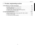
Page 5: ...b Main Specifications I 3 c Major Selling Points and Improvements I 4 d Evaluation of Competitive Power with Competitors I 8 e Actual performance comparison I 11 B Machine specifications I 12 a Major...

Page 6: ...WSM U15 3 I 2...

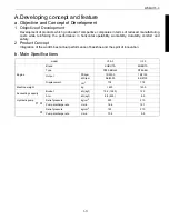
Page 7: ...t Concept Integration of the world s best actual performance of backhoe and the spirit of innovation b Main Specifications model U15 3 U 15 Engine Brand KUBOTA KUBOTA Type D782 EBH 4 D782 BH Output PS...

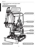
Page 8: ...version EU option Inner package of hoses for all attachments Max excavation capacity increased by 22 Max excavation depth increased by 10 4 port ROPS specification Engine start control Travel lock fu...

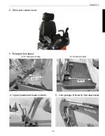
Page 9: ...WSM U15 3 I 5 2 Wrist arm control lever 3 Enlarged foot space 330mm U 15 Previous model 460mm U15 3 New model 4 Upper positioned boom cylinder 5 Inner package of hoses for front attachments...

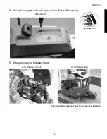
Page 10: ...gine start control Travel lock function 7 4 post ROPS The equipment is of European specifications Unloading lever UP Engine start Front attachment traveling Unloading lever DOWN Engine start Front att...

Page 11: ...Machine equipped with theft proof device Future EU option 9 Side opening type full open hood Paint color and equipment are of European specifications Starter key set Antenna unit U 15 Previous model...

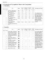
Page 12: ...eling force increased by 12 Item U15 3 Current U 15 KOMATSU PC15MR YANMAR Vio15 SCM 301 5CR Appealing point in sales Offence Defense Boom cylinder Protection of cylinder by high positioning x x x x As...

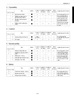
Page 13: ...e Ample getting on off space Front operation We will appeal the ampleness of getting on off space Flat steps x Item U15 3 Current U 15 KOMATSU PC15MR YANMAR Vio15 SCM 301 5CR Appealing point in sales...

Page 14: ...ce Max excavation depth 2310 2100 210 Max vertical excavation depth 1900 1720 180 Max excavation radius 3900 3720 180 Max excavation height 3540 3740 200 Max dumping height 2440 2600 160 Max floor exc...

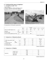
Page 15: ...Increasin g rate PC15MR 1 Vio15 2 301 5CR Volume of soil discharged per hour m3 h 31 4 25 0 26 24 3 26 3 25 9 Cycle time sec 8 3 9 8 15 Fuel consumption cc 10min 400 390 Volume of soil discharged per...

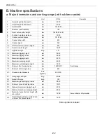
Page 16: ...ch angle deg 30 1 13 Maximum digging height mm 3540 14 Maximum digging radius mm 3900 15 Maximum digging depth mm 2310 16 Maximum dumping height mm 2440 17 Maximum vertical digging depth mm 1910 18 Mi...

Page 17: ...M U15 3 I 13 b Dimensional drawings 410 485 990 1240 620 980 990 1240 3540 2440 2310 1910 1430 2250 2630 265 180 2750 825 3570 3840 3900 A B C D E F G H I J K L M N O P Q R S T mm from operator s manu...

Page 18: ...bucket and dump soil on the ground after 45 swivel Unit U15 3 Remarks Standard bucket capacity heaped m3 0 04 CECE Maximum digging force arm KN kgf 8 8 900 Teeth bottom Maximum digging force bucket K...

Page 19: ...n the ground surface condition dozer s ground contact status operator s weight remaining fuel and other factors 3 The boom swing position is set at the center The machine may turn over if it is set of...

Page 20: ...WSM U15 3 I 16...

Page 21: ...Performance curves II 45 c Engine electrical data II 46 d Engine servicing data II 47 e Engine Mount II 48 f Fuel System II 49 g Cooling system II 52 h Air cleaner II 54 D Hydraulic system II 55 a Mai...

Page 22: ...i Auto glow circuit II 134 j Auto release control system II 144 k Water temp sensor gauge II 151 l Fuel control circuit II 153 m Engine stop solenoid II 154 n coil commander II 156 o Fuel sensor II 15...

Page 23: ...ine oil at filter replacement L 3 5 Class CC 10W30 Hydraulic tank oil L 13 ISO 46 Total hydraulic oil L 22 ISO 46 Wheel motor gear oil L 0 25 SAE 90 API GL 4 Swivel reducer gear oil L Track roller gea...

Page 24: ...1 4 0 4 6 Counterweight 107 9 125 5 11 0 12 8 Oil tank Coupling 48 1 55 9 4 9 5 7 Main pump 77 5 90 2 7 9 9 2 Rotary joint 48 1 55 9 4 9 5 7 Rotary joint stopper 48 1 55 9 4 9 5 7 Muffler flange 23 5...

Page 25: ...on nut Taper thread 1 8 7 8 11 8 0 8 1 2 19 6 29 4 2 0 3 0 17 1 4 24 5 29 4 2 5 3 0 36 3 44 1 3 7 4 5 19 3 8 37 2 42 1 3 8 4 3 68 6 73 5 7 0 7 5 22 1 2 58 8 63 7 6 0 6 5 83 4 88 3 8 5 9 0 27 3 4 117 7...

Page 26: ...12 2 Swivel frame rear ground clearance mm 422 8 3 Tambler center distance mm 1230 37 4 Crawler total length mm 1587 48 5 Crawler total width mm 1240 990 26 6 Crawler shoe width mm 230 5 7 Min ground...

Page 27: ...ging force kgf 1 55 N 15 2 10 1 Dozer Width mm 1244 990 5 2 Height mm 261 5 4 Max lift above GL mm 263 13 5 Max below GL mm 182 9 11 4 Water oil Fuel Tank L 17 5 0 9 5 Hydraulic oil Tank L 13 0 7 Q2 M...

Page 28: ...5 C 2 extend sec 2 4 0 3 Oil temp 50 5 C 7 1 Bucket speed crowd sec 2 8 0 3 Oil temp 50 5 C 2 dump sec 1 9 0 3 Oil temp 50 5 C 8 1 Dozer speed up sec 1 4 0 3 Max down to max up 2 down sec 1 9 0 3 Max...

Page 29: ...ow No load load L 27 Q8 Lever operating force stroke 1 1 Boom lever operating force kgf 1 4 0 5 Measured 20 mm below the grip end kN 13 7 4 9 4 Arm lever kgf 1 4 0 5 N 13 7 4 9 5 Bucket lever kgf 1 4...

Page 30: ...cket weight 37Kg N Over end dozer up kgf N 2 Bucket load to tipping track frame extended Side dozer up kgf 121 N 1187 Over end dozer up kgf 130 N 1275 3 Bucket load to tipping track frame retracked Si...

Page 31: ...ed within 10 m in radius from the machine imaginary hemispherical space with the machine length from 1 5 to 4 m Unit U15 3 Remarks At ear level Canopy db A 78 Around the machine db A Acoustic power le...

Page 32: ...g bracket kg 28 Boom kg 67 Arm kg 30 Bucket kg 29 450 400 Dozer kg 67 Counterweight kg 205 Iron crawler kg 89 Rubber crawler kg 56 Unit U15 3 Remarks Engine kg 64 Dry weight Hydraulic tank kg 13 With...

Page 33: ...del the travel Hi Low control switch is located on the dozer lever grip 1 Service port pedal 9 Fuel tank 2 Control valve 10 Swivel motor 3 Oil cooler 11 Swivel joint 4 Battery 12 Oil tank 5 Radiator 1...

Page 34: ...ront attachments left 3 Lock lever for attachment control 4 Service port pedal 5 Travel lever right 6 Control lever for front attachments right 7 Two travel speed switch 8 Control lever for dozer or t...

Page 35: ...meter oil level gauge and Easy checker oil lamp charge lamp glow lamp and fuel level alarm lamp for various indications 1 Horn switch 2 Starter switch 3 Malfunction indicator Quick Diagnosis 4 Fuel me...

Page 36: ...hecked and cleaned by opening the left hood Machine front Machine front o Idle 1 Starter Switch A STOP B RUN C START Max Idle Max 1 2 3 4 5 1 Hood Left 4 Oil cooler 2 Hood Rear 5 Radiator 3 Wing nut 1...

Page 37: ...oil is filled up A hydraulic oil filler port is provided also at the side of the fuel filler port Like in the models of KX91 3S D and KX121 3S D Series the fuel filter has been separated from the wat...

Page 38: ...1 Bucket link 1 side 2 Arm end 3 Bucket link 1 side 4 Arm boss side 5 Arm boss side 6 Tensile brass 1 Dust seal magnified view 7 Dust seal 2 Bush side 8 Bush inserting direction 3 Outside 9 Bush 4 Bus...

Page 39: ...to the front for both bucket and SP 21 Red 13 Pay attention to the direction of the cushion 6 22 Black 14 Fix the hoses for both bucket and SP so that they should face up forwards 23 Color of hose ta...

Page 40: ...greasing 5 Type A Boss greasing 14 As viewed from front of the swivel frame 6 Type A Pin greasing 15 Swing cylinder bottom 7 Type A Boss greasing 16 Swivel bearing teeth 8 Type A Boss greasing 17 Swiv...

Page 41: ...5 3 II 21 6 Greasing 2 1 2 3 4 5 A type Straight type 06611 15010 B type 67 C 06616 25010 C type 90 C 06616 35010 1 Type A Boss greasing 2 Type B Boss greasing 3 Type B Boss greasing 4 Type B Boss gre...

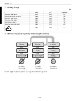
Page 42: ...ions 2 Switch the track width change dozer select lever to the Track width change position 3 Push the control lever forward and expand the track width to 1240 mm 4 Remove soil and sand adhered to the...

Page 43: ...5 3 Remarks 1 mm 400 Lip outside width 2 mm 456 Side cutter outside width 3 mm 60 5 x 6 I x t 4 mm 139 5 5 mm 95 5 Arm end width 6 mm 16 7 mm 22 8 mm 47 75 9 mm I49 10 mm I60 11 mm I30 12 mm I30 13 mm...

Page 44: ...3 II 24 2 Bucket fixture dimensions Unit U15 3 Remarks A mm 45 3 B mm 2 x M12 x 1 25 C mm 45 3 D mm 45 3 E mm 16 5 F mm 3 95 G mm 865 H mm 2 I mm 180 J mm 167 5 K mm 104 5 L mm 735 M mm 173 N mm 175...

Page 45: ...ts name Specifications 1 Bucket link 1 I30 x 95 5 2 Bush A I30 x I38 x W35 3 Pin A dia I30 x 192 5 5 Bucket link 2 3 I30 I30 6 Arm boss I55 x I38 x L125 5 7 Bush B I30 x I38 x W35 8 Pin B dia I30 x 19...

Page 46: ...44 3 I35 x 160 I35 x I45 x 45 4 I30 x 112 5 I30 x I40 x 35 5 I30 x 96 I30 x I40 x 35 6 I50 x 109 I50 x I60 x 37 28 40 7 I50 x 109 I50 x I60 x 37 28 40 8 I30 x 160 I30 x I40 x 35 9 I30 x 142 I30 x I40...

Page 47: ...ng 9 Side of the bush 3 should flash the face 10 After installing the bush pin of I34 9 goes through smoothy 11 Side of the bush 2 should behind the surface 12 After installing the bush pin of I49 95...

Page 48: ...e N kgf 13 7 1 4 Measured 20 mm below the grip end Play mm 2 Travel lever Stroke mm 75 Measured at the grip end Operating force N kgf 15 0 1 5 Measured 20 mm below the grip end Clearance LH RH lever a...

Page 49: ...11 Cable Accelerator 1 Bush 2 12 Headed pin 1 3 Lever grip 2 1 13 Snap pin 6 1 4 Plain washer 1 14 Plain washer 1 5 Plain washer 2 15 Support Accelerator 1 6 Disc spring 2 16 Bolt 2 M8 7T 7 Nut 2 17 P...

Page 50: ...r No Part Name Q ty Remarks 1 Lever assembly Blade 1 Lever Blade 1 Bush 2 2 Grip 1 3 Seal Lever blade 1 4 Cable Blade 1 Plain washer 1 Snap pin 1 5 Bracket Cable blade 1 6 Dimensions in the parenthese...

Page 51: ...the cable behind the welded member of the bracket muffler Pass the cable along the inside of the welded member of the swivel frame Pass the cable through the 2 holes of the vertical ribs at the left...

Page 52: ...2 6 Lever assembly Swing pedal 1 2 Plain washer 1 Lever Swing pedal 1 3 Snap pin 1 Bush 2 4 Rod Swing 1 7 Pedal 1 Rod end right hand screw 1 Bolt 1 Nut 2 Plain washer 2 Spring washer 1 Jam nut 1 Plain...

Page 53: ...mbly SP pedal 1 Lever SP pedal 1 Bush 2 2 Pedal 1 Bolt 1 Plain washer 1 Jam nut 1 3 Rod SP 2 Rod end right hand screw 1 Nut Spring washer 1 Plain washer 1 Snap pin 4 Assemble so that the pedal upper s...

Page 54: ...tom surface hardness 52 60 HRC See the Gear Specifications for gear hardening details 5 Inner ring S marking and outer ring s stopper on the soft zone When installing the bearing position the soft zon...

Page 55: ...h the left and right sides of the frame 2 Loosen the play adjusting setbolts by 1 4 turns when they have reached the frame 3 Lock the adjusting setbolts by nuts No Part Name Q ty 1 Set bolt RA221 2116...

Page 56: ...smoothly after it has been assembled completely 5 Dimensions of assembling jigs for seal etc and the assembling procedure are equivalent to those of RA211 2170 No Part Name Q ty Remarks 1 Track rolle...

Page 57: ...Cylinder assembly Left 1 Cylinder assembly Right 1 3 Nipple Grease cylinder 2 Both iron and rubber springs can be used compatively In the case of rubber roller adjust it so that the joint mark f shou...

Page 58: ...Plug R 1 8 14 Nut 3 shaft 7 O ring 11 Yoke 15 Split pin 4 Idler 8 Spring pin 12 Spring 16 Bolt L 1 Pre set length of spring L 130 mm 5 12 inch 2 Bolt 16 tightening torque 77 5 90 2 N m 7 9 9 2 kgf m 3...

Page 59: ...cle B Allowable limit Unit U15 3 Remarks Idler a Outside diameter A B mm 202 196 Rubber Crawler 196 190 Steel Crawler b Guide width A B mm 27 23 c Idler width A B mm 60 55 Sprocket d Outside diameter...

Page 60: ...0 mm Iron core pitch 96 0 mm Circunference 3360 10 mm Number of steel cords 48 4 Steel cords lap length 260 mm Steel cords strength 3 92 KN 400 kgf or more Thickness of crawler main part 23 0 mm Ditto...

Page 61: ...l tread height A B mm 56 51 c Collar outside diameter mm 22 20 5 d Collar inside diameter mm 14 16 e Master pin outside diameter mm 14 12 5 f Grouser height A B mm 16 5 8 Including plate Crawler width...

Page 62: ...15 3 II 42 9 Iron track shoe Tighten hex nuts to torque of 70 100 N m Rubber pad Link Bushing Over 25 when assembled Bushing Link Pin Inside Outside Common for both ends Inside Outside Common for both...

Page 63: ...m I30 84 5 4 Outside diameter Length mm I30 95 Track cylinder mounting pin 5 Outside diameter Length mm I25 133 Extension blade mounting pin A Width mm 1244 990 B Height mm 261 C Length mm 710 D Tip w...

Page 64: ...amber E TVCS Type of fuel injection pump Bosch MD mini pump Type of governor Centrifugal mechanical governor Type of injection nozzle DN4PD52 mini nozzle Fuel injection timing deg BTDC14 16 15p 17p pr...

Page 65: ...WSM U15 3 II 45 b Performance curves...

Page 66: ...jection pressure Mpa kgf cm2 13 8 14 7 140 150 Electrical system Charging generator V W 12 480 Denso specified type Part code electricals V10505 B AEBI 1 Charging current A 40 Regulator adjusted volta...

Page 67: ...0 30 1 2 Top Compression ring A B mm 0 30 0 45 1 2 Second Piston outside diameter mm I67 Timing gear backlash A B mm 0 041 0 124 0 15 Compression pressure A B Mpa kgf cm2 3 0 3 4 31 35 2 5 25 Differen...

Page 68: ...WSM U15 3 II 48 e Engine Mount 1 Vibration proof rubber 2 Cover Rubber sheet 3 Rounded part 4 Bracket Engine rear 5 Stopper Engine 6 Bracket Engine rear 7 Vibration proof rubber 1 4 2 3 5 6 7...

Page 69: ...Engine fuel return port 4 Fuel tube 1 L 280 15 Joint Fuel drain 5 Fuel tube 1 L 140 16 Fuel tank assembly 6 Fuel tube 1 L 140 17 Filter assembly Fuel 7 Fuel tube 1 L 150 18 Pump assembly Fuel 8 Fuel t...

Page 70: ...ly Fuel 12 Fuel tank upper part 4 Fuel tank Upper 13 Clamp 5 Fuel tank Lower 14 Pass it under the cover tank return 6 Clamp 15 Fuel tank lower part 7 Water separator 16 Clamp 8 Fuel tank 17 Pass it ov...

Page 71: ...mbly Fuel filter Packing 4 Sensor fuel 5 Machine screw with spring 6 Fuel level gauge assembly 7 Tightening torque 8 Fuel level 15 2L 9 Fuel level 2 2L Note No leak is allowed under air pressure of 29...

Page 72: ...WSM U15 3 II 52 g Cooling system 1 Structure Hole Clamp Cap Through Cap pressure...

Page 73: ...Hg Valve opening pressure Press kPa 147 1 5 kgf cm2 Vacuum kPa Test pressure kPa 147 1 5 kgf cm2 Vibration durability Acceleration 6 G Direct Up down Cycle 22 3 Hz Cycle 10 Structural specifications C...

Page 74: ...s 8 powder Dust concentration 1 g m3 Air flow resistance 2 94 kPa 300 mmAg Full life for an increase Cleaning efficiency Initial Full life Above 99 Above 99 9 Dust containment g Above 50 Filtering are...

Page 75: ...WSM U15 3 II 55 D Hydraulic system a Main pump 1 Outer view 2 Pump coupling 1 Suction port 2 4 M10 3 Oil inlet 4 Discharge port 5 Rotation direction Clockwise 1 2 4 3 4 4 4 5 Two Point Pitch...

Page 76: ...sembly Piston 1 2 Pipe joint L G3 8 G3 8 1 3 Pipe joint L G3 8 G3 8 1 R1 8 P1 P2 P3 P4 4 Pipe joint L G3 8 G3 8 1 5 Pipe joint L G3 8 G1 4 1 6 O ring 1 7 Plug 4 For 3 8 8 Flange Suction 1 9 Bolt 4 M10...

Page 77: ...O ring 66 Coupling 4 Cylinder barrel 13 Packin 27 Pin 44 Hex bolt 67 Collar 5 Valve plate 14 Spring C 30 Ball bearing 49 Hex plug 68 Bolt 6 Piston 15 Spring T 31 Needle bearing 51 Plug 69 O ring 7 Sho...

Page 78: ...harge q 1 q 2 cc rev Pressure P1 P2 kgf cm2 Test condition Remark Oil ISOVG46 Pump intake torque 3 44 kgf m Oil temp 50 5 C at P3 5 kgf cm2 RPM 2300 rpm 3 44 kgf m Direction Clockwise at P3 190 kgf cm...

Page 79: ...at P3 0 49 MPa T 37 0 N m at P3 20 6 MPa T 39 0 N m 9 Pump discharge P1 P2 16 56 l min x 2 P3 10 35 l min P4 6 21 l min 4 37 us gal min 2 73 us gal min 1 64 us gal min Unit U15 3 Remarks P1 P2 maker s...

Page 80: ...o discharge grooves as shown in Fig 3 The discharge grooves P1 and P2 are located in the outer and inner sides respectively Every other piston cham ber of cylinder barrel gets open to either of these...

Page 81: ...230 10 P Working part Bucket Bench set pressure Mpa kgf cm2 21 6 220 Machine set pressure Mpa kgf cm2 225 10 P2 Working part Arm Bench set pressure Mpa kgf cm2 21 6 220 Machine set pressure Mpa kgf c...

Page 82: ...Pipe joint L G1 8 G1 4 3 22 Pipe joint S G1 8 G1 4 3 7 Pipe joint S G1 4 G1 4 3 23 Pipe joint S G3 8 G3 8 1 8 Pipe joint S G3 8 G3 4 2 24 Pipe joint L G3 8 G3 8 6 9 Pipe joint L G1 2 14 1 25 Pipe joi...

Page 83: ...WSM U15 3 II 63 3 Control Valve 2 Front Rear...

Page 84: ...rking provided ID marking provided Tightening torque T 13 7 14 7N m 1 4 1 5kgf m Stroke Swing dozer service travel left right Thread depth 12 Actuator port Unload confluence valve 4 mm stroke Stroke m...

Page 85: ...lic oil Operating oil temperature range 20 90 C 100 C Oil contamination level Within Class NAS9 Operating conditions Relief valve set pressure P1 P2 21 4 MPa 218 kgf cm2 at 16 6 L min P3 18 4 MPa 188...

Page 86: ...ing torque T 3 92 N m T 0 4 kgf m Tightening torque T 3 92 4 90 N m T 0 4 0 5 kgf m at 10 4 L min Setting 18 4 MPa 188 kgf cm2 0 49 0 5 0 Tightening torque T 3 92 4 90 N m T 0 4 0 5 kgf m Tightening t...

Page 87: ...htening torque T 39 2 N m T 4 0 kgf m at 5 L min Setting 17 5 MPa 178 kgf cm2 0 49 0 5 0 Tightening torque T 39 2 N m T 4 0 kgf m at 18 8 L min Setting 21 4 MPa 218 kgf cm2 0 49 0 5 0 Tightening torqu...

Page 88: ...WSM U15 3 II 68 7 Inner sectional view Tightening torque T 13 7 14 7 N m T 1 4 1 5 kgf m...

Page 89: ...tal heaped 15 engine at stop Allowable slope angle for swivel deg kg 18 Front horizontal heaped engine at max rpm Play at bucket tip mm 73 20 How to measure the play at bucket tip 1 Dump the arm and c...

Page 90: ...A D and 030 060 030 Bearing ball 1 040 Bearing ball 1 050 Plug 1 060 Retainer 1 070 Plate 1 080 Plate valve 1 090 Valve 1 100 Plate 1 110 Spring 2 120 Pin 2 130 Drive 1 140 Gear roller 1 150 Valve dri...

Page 91: ...l 1 34 O ring 2 1BP16 10 Wear plate 1 35 Needle valve 2 11 O ring 2 AS568 041 36 Spring washer 2 12 Valve plate 1 37 Spring presser 2 13 O ring 1 AS568 038 38 Orifice plate 2 14 Valve 1 39 Spring 2 15...

Page 92: ...Remarks 1 Motor assembly Swivel 1 2 Pipe joint S G3 8 G1 4 1 A 3 Pipe joint L G1 4 G1 4 1 For 3 8 A 4 Pipe joint L G3 8 G1 4 1 B 5 Pipe joint S G3 8 13 1 T O ring 1 T 6 Pipe joint L G3 8 G3 8 1 For 3...

Page 93: ...countersunk 2 x G3 8 A and B ports 28 countersunk G1 8 PP port 18 countersunk 8 x M10 x 1 5 through 8 equally spaced 9 x M10 x 1 5 through 9 equally spaced 2 x G3 8 lube oil filler discharge port Hydr...

Page 94: ...ev Max pressure 21 6 MPa 220 kgf cm2 Max speed 1461 2867 min 1 Max oil flow 16 6 l min Hi Low change pressure 0 5 MPa 5 kgf cm2 Others Equivalent capacity for one turn of motor assy 419 9 214 0 cm3 re...

Page 95: ...one minutes New machine s drain specifications Rotating l min 0 5 Drain machine body raised Locked cc min 90 180 180 420 1F 2F actual measurement sample data Rotating cc min 5 20 20 45 1F 2F actual m...

Page 96: ...Name Q ty 1 Drive Sprocket 2 2 Hex socket bolt 18 3 Motor assembly Wheel 2 4 Hex socket bolt 16 5 Spring washer 16 6 Pipe joint S G1 4 G1 4 2 7 Pipe joint S G1 8 G1 4 2 8 Adaptor 2 9 O ring 2 10 Strai...

Page 97: ...WSM U15 3 II 77 4 Structure 1 Counter balance valve 4 Selector valve 2 HI Lo change valve 5 Hi Lo piston 3 Selector valve 1 2 4 3 5 b1 b2 S2 S1 a1 a2 1 2 4 5 1...

Page 98: ...ionary main body composed of a hydraulic motor and hydrau lic valve and a rotating main body composed of a simple planetary gear reducer 1 Stationary part 5 Hydraulic motor 2 Rotating part 6 Symple pl...

Page 99: ...d revo lution is double reduced through the gears S1 b1 a1 spline coupled with the carrier 2 The reduced revolution is transmitted to the rotating main body through the annular gears a1 and a2 providi...

Page 100: ...s into the cylinder port which corresponds to the port A in the cylinder barrel 4 and presses the piston 6 This pressing force is converted to turning force through the swash plate 7 and the resulting...

Page 101: ...speed selector lever is switched to the g2nd speed position the operating pressure is con ducted through the two speed spool to the control room and the control piston moves until the face II of the s...

Page 102: ...make the hydraulic motor rotate When the pressure oil is supplied through the port B the above mentioned pro cesses are reversed and the hydraulic motor rotates reversely When the pressure oil suppli...

Page 103: ...x the adjust nut with a spanner when mountting the lever and tighten the lock nut customor s supply with 41 2 2 9N m 420 30kgf cm 6 G1 4 Thread depth 12 O ring seal to JIS B 2351 Spot facing DIA 24 de...

Page 104: ...0 C 90 C 9 Filter A filter of 40 mesh and over should be applied at the entrance of port P for proventing the spool sticking 3 Operating specifications 1 Primary pressure 3 9MPa 40 kgf cm2 4 Max allow...

Page 105: ...er 2 221 Spring 241 Spring 301 Joint 302 Plate circular 312 Nut adjusting 501 Bellows Grease is applied on each rotational part of the universal joint Pay attention to the direction of assembling the...

Page 106: ...g Blue 2 Boom lowering Light blue 3 Swivel Right Yellow 3 Bucket dumping Brown 4 Arm raking Green 4 Boom raising Gray P P port White P P port White T T port None T T port None No Part Name Q ty Remark...

Page 107: ...pty bucket crowded Arm cylinder Crowd A B sec 3 5 0 3 Dump A B sec 2 4 0 3 Bucket cylinder Crowd A B sec 2 8 0 3 Dump A B sec 1 9 0 3 Boom swing cylinder LH A B sec 4 6 0 3 RH A B sec 3 7 0 3 Dozer cy...

Page 108: ...5 Sealing kit part code YW182 9531 Piston tightening torque N m kgf m 510 550 52 56 Piston thread size M24 x 1 5 Piston wrench size mm 36 Unit U15 3 Remarks Bucket Tube outside diameter Inside diamete...

Page 109: ...er Inside diameter Rod outside diameter mm 65 55 30 Stroke mm 250 Fully retracted mm 478 Sealing kit part code YW178 9511 Piston tightening torque N m kgf m 343 395 35 40 Piston thread size mm M22 x 1...

Page 110: ...1 Cylinder tube 6 Backup ring 11 DU bushing Bucket Arm 2 Cylinder rod 7 Scraper 12 Piston 17 Stroke 269 335 5 3 Bushing 8 O ring 13 Piston seal 18 Retracted L 529 589 1 5 4 Cylinder head 9 Backup rin...

Page 111: ...load Oil tempera ture 50 5 deg 5 Withstanding pressure Permanent deformation and oil leakage must not occur after pressure 2 times as high as the main relief pressure 43 1 MPa 440 kgf cm2 is applied...

Page 112: ...33 Blade cyl Bottom 23 Travel drain d 34 Blade cyl Rod O rings are adopted at upper and lower sides for prevention of water entry 13 Right 14 15 16 17 18 19 20 21 24 23 22 25 26 27 28 29 34 33 32 31 3...

Page 113: ...1 Shaft Swivel joint 1 2 Ring Backup 18 3 Ring D 9 4 Ring Backup 2 5 O ring 2 6 Collar 1 7 Body Swivel joint 1 8 Plug R1 8 2 9 Collar 1 10 Shaft circlip 1 11 Plug R1 8 2 12 Base Swivel joint 7 13 Bol...

Page 114: ...ry joint b Relay 1 310 Rotary joint c Relay 1 310 5 Rotary joint b Relay 1 310 Rotary joint c Relay 1 310 6 Relay Dozer cyl rod 1 930 7 Relay Dozer cyl rod 1 660 Machine left side Dozer Machine right...

Page 115: ...To cyl rod side 3 To cyl bottom side 4 Adjust the angle of the adaptor and secure the clearance between the plate of C and the hose to be more than 1 mm and less than 10 mm 5 Clamp the hose at this po...

Page 116: ...ecifications 1 Allowable voltage DC 10 8 14 4V 2 Current 1 2 A at 20 C 3 Power consump tion 14 4W 4 Coil resistance Approx 10 at 20 C 5 Insulation JIS C 4003 H 6 Surge killer Diode 7 Relief valve set...

Page 117: ...Right side P O ring 1 For G3 8 P 11 PV Left side P 3 Pipe joint L G1 4 G1 4 1 B 12 Unloading 4 T pipe joint F2 1 B 13 2 speed 5 Shouldered elbow 1 B 14 CV Pp O ring 1 For G1 4 A 15 Pump P4 6 Pipe joi...

Page 118: ...ructure 2 Function This valve is to select the oil flow direction for blade cylinder or track cylinder 3 Specifications 1 Operating pressure and flow Main relief pressure 20 6 MPa at 10 4 l min 2 Insi...

Page 119: ...in 70 l min 4 Hex spanner 41 mm 36 mm 5 Filter dia I 85 I 90 6 Filter length 105 125 7 Relief opening pressure 0 1MPa 1 0 0 15 kgf cm2 8 Code number RB238 62151 RA011 62191 mm Cracking pressure 196 29...

Page 120: ...alve O ring 1 13 Direct the pipe joint F2 as shown in the figure 4 Plug Oil filler 1 14 Press it securely up to the hilt O ring 1 15 Hose Suction 5 Bolt 6 16 Pump 6 Filter Suction 1 17 Pipe Return 7 G...

Page 121: ...re loss Pa mmAq 118 Test pressure kPa Kgf cm2 981 10 Repeated pressure resistance kPa Kgf cm2 981 10 x 105 times Static pressure breakdown kPa Kgf cm2 2 45 25 Structural specifications Type of core Dr...

Page 122: ...MPa 70 kgf m2 4 Initial gas pressure 1 2 MPa 12kgf m2 at 20 C 5 Operating oil temp 30 100 C 6 Weight 1 1 kgf Machine models used U15 3 U20 3 U25 3 warning It contains nitrogen under high pressure Don...

Page 123: ...Forward 1 22 Pump 6 CV A6 SJ F Blue Travel Right Backward 1 7 CV B6 SJ E Red Travel Right Forward 6 8 CV B3 Swivel Motor B Gray Swivel Left 1 9 CV A3 Swivel Motor A Light blue Swivel Right 1 10 CV A1...

Page 124: ...l cooler OUT 1 8 Control valve 2 CV T3 Oil cooler Rear Oil cooler IN 1 9 Return pipe 3 CV T2 Pipe return Oil cooler bypass 1 10 Oil cooler 4 Pipe return Oil tank Return 1 11 Swivel motor 5 Swivel moto...

Page 125: ...r 11 Swing With the unload lever being raised oil of P1 and P2 flows from the supply section directly to the return circuit and results in no functions of P1 and P2 pump from bucket 1 to service port...

Page 126: ...to joint P1 and P3 5 Service port Confluence When service port pedal is depressed P2 and P3 pump s oil will be supplied to service port section P1 P2 P3 P 1 2 3 4 5 6 7 8 9 10 11 1 Bucket 2 Boom 3 Tra...

Page 127: ...ince only the Boom and Service are jointed with P3 straight travel is possible When left and right travel levers are shifted F or R P1 supplies oil to the travel motor and P2 to the right motor P3 sup...

Page 128: ...2 Port B Push the right part of the pedal to send oil to the port A Push the left part of the pedal to send oil to the port B IMPORTANT When the service port is not used for a long period dirt particl...

Page 129: ...has been installed on the control valve When the breaker will be used position the lever of selection valve to the OPENED position 1 way circuit to reduce the back pressure IMPORTANT When the equipmen...

Page 130: ...WSM U15 3 II 110...

Page 131: ...Unload valve 6 Control valve 7 Swivel motor 8 Rotary joint 9 Travel motor L 10 Travel motor R 11 Change valve for SP 1 way 2 way 12 Change valve Dozer track 13 Hydraulic oil tank 14 Oil cooler 15 Boo...

Page 132: ...WSM U15 3 II 112 n Hydraulic circuit diagram...

Page 133: ...me required for starting the engine At the starting position the glow plug is pre heated irrespective of water temperature 3 Theft proof Specification This is different from 3 ton 4 ton class machines...

Page 134: ...60A fuse is added close to the alternator otherwise part of the harness may get short circuited due to the alternator s current generated while the engine is running In this way the devices and harne...

Page 135: ...WSM U15 3 II 115 c Key switch Engine starter switch Contact I3 water drain Rotor Dust seal Return spring Detent O ring Key position 30 AC Start Off z 1st AC position z z 2nd Start position z z z...

Page 136: ...cifications 1 Rated DC14V 1 5A 2 Insulasion 2M or more 3 Operationg force of plunger at Free position 17 3 N at Max stroke 32 4 N 4 Full stroke 9 5 mm PVC tube black stroke apply silicone resin Crimp...

Page 137: ...out of the lever lock solenoid valve Pull by a 3 kg or less force 3 Continuity test of corresponding harness are required 4 Solenoid valve check 1 Coil resistance test Specification Approx 10 at 20 C...

Page 138: ...turns of coil dI Rate of magnetic flex I variation in short interval dt second E N dI 1 Alow voltage DC 10 8 14 4V 2 Current 1 2 A at 20 C 3 Power consumption 14 4 W 4 Coil resistance Approx 10 at 20...

Page 139: ...ec tion between the positive output terminal of the built in battery and the cathode of the diode 1 Construction and principle of circuit tester Fig in the left shows the inside of an ohmmeter The bui...

Page 140: ...ystem functions Now go to the hydraulic system 6 Possible troubles with the hydraulic system include stuck solenoid spool poorly performing pilot pump malfunctioning primary relief valve stuck Hi Lo s...

Page 141: ...ng Hi Low SW 1 Location of Hi Low SW coupler and how to disconnect the coupler Small size driver match repair driver is required 2 Check battery 12V 3 Check continuity of the switch 4 Testing Hi Low s...

Page 142: ...2 ON 13 1 ON 306 2 ON 306 2 ON 306 1 ON 306 3 ON 306 3 ON 306 3 ON 306 1 ON 306 4 ON 306 2 ON 306 1 ON 306 4 ON 800 1 ON 800 1 ON 800 1 ON 801 2 ON 801 2 ON 801 2 ON 306 1 ON 306 2 ON 306 3 ON 801 1 O...

Page 143: ...high speed ON condition relays 1 Travel hi low drive relay 4 Negative function relay 1 Travel hi low drive relay 6 Second self hold relay 2 Travel hi low solenoid 7 Main Key SW 3 Travel hi low SW 8 L...

Page 144: ...cond self hold relay 9 Self hold cancel relay 6 Push the travel high low SW ON again Hold the SW button ON When the travel high low SW is pushed ON battery current flows through the coil of travel hig...

Page 145: ...he machine previously at high speed conditions Note Lever lock SW 8 was not installed as shown above for the early production machines It was connected with unload valve solenoid only Therefore in the...

Page 146: ...e main key SW ON and OFF or shift the lever lock SW Up and Down while holding the travel high low SW But normally operator won t do This is just for your information Key SW Hi Low SW Hi Low solenoid O...

Page 147: ...U15 3 II 127 g Meter panel 5 4 2 6 1 7 3 2 1 1 Installation view 1 Meter panel 2 Main key SW 3 Horn SW 4 Hi Low SW 5 Dozer lever 6 Accel lever 7 Work lamp SW 2 Mater inside view 1 Horn meter 2 Fuel ga...

Page 148: ...is a malfunction in the charge system The lamp lights up when the Starter Switch is in posi tion RUN and goes out as soon as the engine starts Indicator Lamp Glow This lamp lights up when the starter...

Page 149: ...raduation F 1 2 E Allowable error 7 5 0 0 7 5 Resistance value 10 38 90 Pin arrangement Code No Point F Point E White number on black background Indicator display Flashing in green every 2 seconds Bla...

Page 150: ...20 ON 1 5 AC Start OFF 1234 5 Back light Fuel Water temp E Oil Press E Oil switch E Oil Pressure Charge Charge Alternator Hi Lo solenoid Glow relay Fuel sensor ON 23 3 ON 23 2 ON 23 1 ON 1 8 ON 1 2 O...

Page 151: ...3 ON 1 4 ON 1 7 ON 1 6 ON 1 10 ON 1 11 ON 1 11 Fuel Glow Travel Hi Lo ON 1 12 ON 1 17 ON 1 14 ON 1 1 ON 1 13 ON 1 15 ON 1 20 ON 1 5 AC Start OFF 1234 5 Back light Fuel Water temp E Oil Press E Oil sw...

Page 152: ...ter function test LED and stepping motor function check Connect the battery 12V to the white harness and the ground to the black wire Check to see LED lights up every two seconds and the internal gear...

Page 153: ...ical circuits If the fusible link is blown check the electrical circuits for trouble and then replace with a new compatible slow blow fuse No Capacity Circuit 1 5A Auto glow 2 5A Anti theft main 3 15A...

Page 154: ...to light up the glow lamp 4 As indicated in Fig 3 Timer curve the pre glow time glow lamp on time t is compensated depending on the water temperature 5 Once the current flows to the relay coil the bat...

Page 155: ...tor resistance Pre glow time sec 140 58 2 55 100 155 2 73 80 277 2 95 60 530 3 37 40 1100 4 22 20 2525 5 85 10 3997 7 12 0 6544 8 77 10 11123 10 81 20 19716 12 00 30 36630 12 00 40 71770 12 00 Key Swi...

Page 156: ...ease controller 14 Water temp sensor 7 Low voltage detection 15 To glow lamp 8 Rotation detection 16 Glow plug ON 32 1 ON 301 11 ON 301 11 ON 32 2 ON 300 1 ON 300 2 ON 300 6 ON 300 5 ON 300 4 ON 300 3...

Page 157: ...1 From altemator 4 Fuse SA 5A 12 Glow relay 5 Auto release stabilizing relay 13 Auto glow controller 6 Auto release controller 14 Water temp sensor 7 Low voltage detection 15 To glow lamp 8 Rotation d...

Page 158: ...uto release controller 14 Water temp sensor 7 Low voltage detection 15 To glow lamp 8 Rotation detection 16 Glow plug ON 32 1 ON 301 11 ON 301 11 ON 32 2 ON 300 1 ON 300 2 ON 300 6 ON 300 5 ON 300 4 O...

Page 159: ...e controller 14 Water temp sensor 7 Low voltage detection 15 To glow lamp 8 Rotation detection 16 Glow plug ON 32 1 ON 301 11 ON 301 11 ON 32 2 ON 300 1 ON 300 2 ON 300 6 ON 300 5 ON 300 4 ON 300 3 ON...

Page 160: ...ected as shown in the diagram the glow lamp stays on for a certain period of time and the relay gets activated it means that the automatic glow controller func tions well 4 If the water temperature se...

Page 161: ...machines 1 Set the key switch to AC position 2 Make sure the glow lamp lights up Auto glow controller defective Does the glow relay turn on Glow lamp broken on meter panel Meter panel power failure T...

Page 162: ...feel the glow relay clicking When it clicks check the glow plug coupler as well as the glow relay If it does not click measure the voltage check for continuity and check the glow relay 3 Voltage check...

Page 163: ...17 2 3 Check for continuity between the glow relay coupler terminal CN17 3 and the glow plug coupler 4 Check for continuity between the glow relay coupler terminal CN17 4 and the battery s positive te...

Page 164: ...starter motor can be protected against key seizure even if the key switch fails to get back ON 14 3 ON 14 1 ON 320 2 ON 320 3 ON 320 1 ON 310 2 ON 310 1 ON 320 4 ON 14 2 off on Start ON 113 ON 25 2 ON...

Page 165: ...OFF condition Even if the main key is turned to the start position 3 Under the condition of low battery voltage approx 6 V or lower and main switch being at start position even at any engine speed th...

Page 166: ...the battery current flows to turn on the starter solenoid switch The start up current from the battery then switches on the starter which gets the engine started 1 Battery 9 Auto release relay 2 Fuse...

Page 167: ...ery 9 Auto release relay 2 Fuse 50A 10 Alternator 3 Key SW 11 Meter panel 4 Fuse SA 5A 12 Starter 5 Auto release stabilizing relay 13 To auto glow controller 6 Auto release controller 7 Low voltage de...

Page 168: ...etection function gets activated and the auto release relay 9 turns off 4 In this way the battery current stops flowing to the starter 2 It helps protect the starter against burnout 1 Battery 9 Auto r...

Page 169: ...is low voltage detection func tions to turn on the transistor and so turn on the auto release relay unconditionally 1 Battery 9 Auto release relay 2 Fuse 50A 10 Alternator 3 Key SW 11 Meter panel 4 Fu...

Page 170: ...WSM U15 3 II 150 8 Auto release and auto glow circuit combined Glow plug Glow lamp...

Page 171: ...the auto glow con troller 1 Check couplers Pull the harness to see if the water temperature sen sor coupler is not out of position Be sure that the cou pler harness is tightly connected Pull by a 3 kg...

Page 172: ...is 0 979V 3 Water temperature sensor check Disconnect the coupler from the water tempera ture sensor and measure the resistance referring to the figure at right The temperature vs resistance curve mu...

Page 173: ...the fuel level has dropped below speci fied however the thermistor gets exposed to the air and becomes smaller in resistance This allows the current to flow to the warning lamp that will light up 123...

Page 174: ...the fuel injection pump is ready to get the engine started Being attracted upward the plunger pushes and opens the contact which discontinues the current flow to the pull in coil With the current sti...

Page 175: ...th as shown in picture 3 Then plunger pin comes out This means pull in coil is normal 4 Take off pull in coil terminal connection 5 Plunger pin still keeps pushing out This means hold coil is normal 6...

Page 176: ...2 Circuit diagram 3 Function Under some condition such as low temp large current flows to pull coil and may cause to cut the coil Coil commander is to regulate the current flow to pull coil by control...

Page 177: ...Check the continuity of hold coil 2 Check pull in coil function after wiring 12V to red and while terminal and ground to black color termi nal Then engine solenoid functions and pull in the plunger he...

Page 178: ...GND AV0 5f black 4 Float arm 16 Unit AV0 5f blue 5 Mount spacer 17 Thermistor AV0 5f black 6 Thermistor assembly 18 When mounted 7 Tank mounting pan head screw dia 19 Manufacturing date code stamped...

Page 179: ...ured with constant current of 40 mA Float position Full 1 2 Empty Resistance 3 32 5 110 Allowable error 2 5 5 Circuit diagram 1466 1358 108 Red Blue Black Gauge Thermister Fuel Unit 1 Pull the harness...

Page 180: ...test lead to the coupler fitted terminal Apply the negative test lead to the plated part to measure the resistance Ref value 4 Directly connect the terminal of wireharness cou pler to the earth Then...

Page 181: ...ressure 0 5 0 1 kgf cm2 5 Insulation resistance 3M or more 1 In normal condition When the engine lube oil pressure goes up the contact of oil switch 6 opens to turn off the lamp 2 In trouble When the...

Page 182: ...cted Pull by a 3 kg or less force If out of position attach the coupler tightly and check the meter reading again 4 Check battery valtage at Terminal of wireharness coupler If no battery voltage check...

Page 183: ...Check engine oil pressure Oil switch operating pressure Ref value 0 05 0 01MPa 0 5 0 1kgf cm2 Idling rpm 0 4 MPa 4 kgf cm2 MAX rpm 0 6 MPa 6 kgf cm2 Oil switch Condition Engine Engine stops starts En...

Page 184: ...the horn drive circuit When the horn switch is pressed current flows to the horn relay to get its contact P1 closed The current from the battery now flows directly through the horn coil and the contac...

Page 185: ...n of diode Prevention of horn switch by absorbing the surge current Inductive type of load such as solenoid valve generates arc spark at switch point This diode installed parallel to solenoid valve le...

Page 186: ...esn t flow through relay So relay remains off condition and horn doesn t sound When horn switch is on position cur rent flows through relay magnetizes it and activates horn Horn SW Diode GND Horn Horn...

Page 187: ...Pulley 2 Nut 3 Collar space 4 Frame assembly drive end 5 Bearing ball 6 Plate retainer 7 Screw 8 Bolt stud 9 Rotor assembly 10 Bearing ball 11 Cover bearing 12 Frame end rear 13 Holder subassembly re...

Page 188: ...minal L Lamp 12V 3 4W x 6 pcs Potential at terminal L Generation off Below 1 5V With alarm on 12V applied at terminal IG Output current at terminal P Average current Below 0 5A Vibration proof overall...

Page 189: ...harness is tightly connected Pull by a 3 kg or less force If out of position attach the coupler tightly and check the lamp 3 Check for continuity to make sure the 60A slow blow fuse 60A is not blown...

Page 190: ...alternator may be loose 2 Next start the engine and measure the voltage being generated while the alternator is running For this measure the voltage between the alternator s termi nal B and the body g...

Page 191: ...cated A large capacity harness may be connected from the power source via the relay to the load In this design the harness is made shorter less expensive and safer A Starter lock relay I Second self h...

Page 192: ...ratings 1 Contact type 1b 2 Contact material Special silver alloy 3 Contact resistance initial Below 50 m DC6V 1A fall of potential method 4 Contact voltage drop Below 0 3 V DC12V 20A fall of potentia...

Page 193: ...ng at this time to the switch is the relay coil current only and is very small 3 The relays may be classified into the normal open type and the normal close type by their contact construction NOTE The...

Page 194: ...nd pass it through the hole 5 5 6 Branch of wire harness 7 Pass it behind the round bar 8 Clamp it at 2 positions 9 Insert a clip into the swivel frame 5 6 1 2 3 4 1 One finger clearance should be sec...

Page 195: ...nit through the hole of the vertical rib 6 Insert RA221 5322 battery cord Plus into the threaded hole from the front side of the mount 7 Facing directly above 8 Clamp the wire harness and the rubber c...

Page 196: ...7 Facing directly above 8 Unloading Left hole Green colored wire harness Upper solenoid 9 2 speed Right hole Yellow colored wire harness Lower solenoid 10 Ground wire 11 Connect the engine stop soleno...

Page 197: ...Wiring Starter Motor Body Grounding 1 Cord Body grounding 2 Battery cord Plus 3 Facing directly below 4 Facing directly above 5 Mount it into the lower hole 6 Projection Rear side 7 Cover Right 8 Groo...

Page 198: ...se stabilizing relay Black Black White wire Red Black wire Black White wire Black White wire D ESS relay Black Red White wire Red White wire Red Black wire Red White wire E Lever lock relay Black Red...

Page 199: ...ve groups and fix them to the working light frame by cord clamps 2 Clamp the position marked with white tape outside the hole Use care so that the wire harness should not be drawn into the hole 3 Tigh...

Page 200: ...WSM U15 3 II 180...

Page 201: ...switch panel Horn Relay Controller Auto Glow Unload valve Stop solenoid Fuse slow blow fuse Lock lever limit switch Glow Battery Oil switch High speed switch Alternator Starter motor Fuel pump Lamp H...

Page 202: ...release stabilizing relay Automatic release controller Low voltage detection Rotation detection Automatic release relay Auto glow controller Water temperature sensor Engine stop Fuel pump Glow relay...

Page 203: ...tch Automatic release stabilizing relay Automatic release controller Low voltage detection Rotation detection Automatic release relay Auto glow controller Water temperature sensor Engine stop Fuel pum...

Page 204: ...matic release stabilizing relay Automatic release controller Low voltage detection Rotation detection Automatic release relay Auto glow controller Water temperature sensor Engine stop Fuel pump Glow r...

Page 205: ...utomatic release stabilizing relay Automatic release controller Low voltage detection Rotation detection Automatic release relay Auto glow controller Water temperature sensor Engine stop Fuel pump Glo...

Page 206: ...se stabilizing relay Automatic release controller Low voltage detection Rotation detection Automatic release relay Auto glow controller OFF OFF OFF Water temperature sensor ON ON ON ON ON ON OFF Engin...

Page 207: ...diagram Japan EU Japan EU 2004 11 16 USA KX91 U35 Soldered to terminals 1 3 Japan EU Japan EU Japan EU Japan EU Japan Japan Japan EU Japan Japan Battery positive terminal LA terminal Soldered Soldere...

Page 208: ...Japan EU Japan EU USA KX91 U35 Soldered to terminals 1 3 Japan EU Japan EU Japan EU Japan EU Japan Japan Japan EU Japan Japan Battery positive terminal LA terminal Soldered Soldered Soldered Soldered...

Page 209: ...ss Conversion Tables...

Page 210: ......

Page 211: ......

Page 212: ...IRAKATA CITY OSAKA JAPAN EDITOR CONSTRUCTION MACHINERY MANUFACTURING DEPT SERVICE ENGINEERING SECTION HIRAKATA PLANT 1 1 1 NAKAMIYA OHIKE HIRAKATA CITY OSAKA JAPAN PHONE 81 72 890 2888 FAX 81 72 890 2...

Reviews: