background image


STEERING SANDER 

FOR WOODEN FLOORS


USER &


MAINTENANCE MANUAL 


Summary of Contents for Gemini 100

Page 1: ... 1 STEERING SANDER FOR WOODEN FLOORS USER MAINTENANCE MANUAL ...

Page 2: ...ody operating the machine should understand how to use and operate it before starting it up Keep this manual for future reference This manual is an ENGLISH translation of the original version in Italian For a new manual contact Kunzle Tasin S r l REGISTERED HEADQUARTERS Via Circonvallazione est 2 6 27023 Cassolnovo PV Italy OPERATIONAL HEADQUARTERS Via Cajkovskij 14 20092 Cinisello Balsamo MI Ital...

Page 3: ... safety measures and warnings 8 Instructions on correct machine use 9 Machine control instructions 10 Machine specifications 11 Machine warnings 12 Prohibited use 12 Starting the machine 12 Machine adjustment procedures 14 Abrasive assembly procedures 14 Adjusting the working surface on the floor 14 Routine maintenance to be performed 14 Sawdust chamber for the user 14 Disc for the user 15 Spheric...

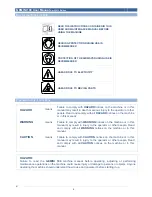
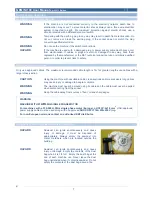
Page 4: ...on the machine or in this manual WARNING means Failure to comply with WARNING notices on the machine or in this manual may result in injury to the operator or other people Read and comply with all WARNING notices on the machine or in this manual CAUTION means Failure to comply with CAUTION notices on the machine or in this manual may result in injury to the operator or other people Read and comply...

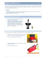
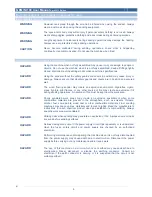
Page 5: ...person 1 Ensure the power supply cable is disconnected from the mains and the machine 2 Always move the sanding machine using the two handles with the bag support turned upwards Protect the sanding discs with abrasive discs When transporting the sanding machine on a vehicle always ensure it is well secured and cannot move Always lift and move the machine with care as it is very heavy Transporting ...

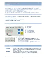
Page 6: ...way from moving mechanical parts The work area is protected with the base frame Machine data plate The following information can be found on the machine data plate 1 Machine model 2 Safety symbols 3 Motor power 4 Frequency 5 Supply voltage 6 Name of manufacturer 7 Country of manufacture 8 Year of manufacture or see serial number 9 Serial number The serial number is formed as follows the first two ...

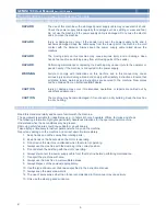
Page 7: ...commended cable length is 7m for greater lengths use cables with a larger cross section CAUTION Using the machine with unsuitable cable cross sections and or excessively long cables may cause injury or damage to people or objects WARNING The machine must never be moved using its cable and the cable must never be pulled when disconnecting from the socket WARNING Keep the cable away from sources of ...

Page 8: ...e environment Cigarettes cigars pipes lighters pilot flames or any other source of fire may create an explosion if lit during sanding operations No sources of fire must be kept near the work area HAZARD Poorly ventilated work areas may create an explosive environment when some combustible materials are present in the atmosphere such as solvents thinners alcohol fuel some paints wood dust or other ...

Page 9: ...mage may occur if maintenance operations or repairs are carried out by unauthorised personnel CAUTION The machine may become damaged if it is not kept in a dry building Keep the machine in a dry building Instructions on correct machine use Read this manual carefully and become familiar with the machine The equipment is suitable for industrial use e g in hotels schools hospitals offices factories a...

Page 10: ...ft disc towards the inside i e towards the right is counterbalanced by the thrust in the opposite direction exerted by the right disc which pushes towards the left The correct operator position for optimum control is behind the machine and not at the side as many tend to do with the hands on the two handles Once the machine has been started it can be noted that it remains quite stationary even tho...

Page 11: ... of the acceleration 1 5 m s2 Net weight 9 kg Gross weight Complete trolley case P N 6899950001 6899950003 Cardboard packages P N 6899950002 16 5 kg 10 kg Machine dimensions Height at handle A Height at suction tube B Width at handle C Base frame width D length B 320 mm 425 mm 255 mm 221 mm 430 mm Packaging dimensions A x B x C Complete trolley case P N 6899950001 6899950003 Cardboard packages P N...

Page 12: ...by anyone ence and kno by a responsi nt is not suita achine to m machine mu mum incline o the machine s may be se is in contac e carefully s miliar with the rators have re e of work nal packagin ref no 3 n pipe by tyin with the ABR 00 mm 12 children incl owledge un ible person t able for colle move objects ust only be u of 2 Do no e when it is o eriously dam ct with the su e machine a ead this man...

Page 13: ...le the discs are lowered and in contact with the work surface 9 To stop the machine raise the discs so that the machine is only resting on the floor with the rear wheel and release the switch as shown by the arrow WARNING The switch must be kept pressed to operate the machine The machine gradually stops when the switch is released or the power supply is interrupted due to unplugging the cable from...

Page 14: ...ro Adjusting the working surface on the floor The discs operate best when slightly tilted with respect to the floor Tilt is determined by the position of the wheel support which is fitted at the rear of the conveyor To change the inclination of the discs loosen the Allen nut and let the support slide on the sanded surface then tighten the nut once the required height has been reached Routine maint...

Page 15: ...the spherical OMNICASTER wheel is self cleaning with regard to sawdust remove dirt from the body of the machine and the wheels regularly Dirt may cause uneven sanding Dust bag for the user Remove the bag and shake it well to remove sawdust Turn the bag inside out and wash it in the machine in cold water to prevent blockage of the pores and a decrease in dust collection ability ...

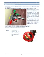
Page 16: ... two graphite brushes that must be checked every six months or after 400 hours of operation The check the brushes carry out the following procedure 1 Remove the screws on the side motor covers with a screwdriver 2 Remove the cover 3 Remove the wire terminal screw 4 Remove the brush complete with spring 5 Check the brushes If one of the brushes is shorter by 7 mm replace both brushes WARNING When f...

Page 17: ...c resin This material is very stiff and therefore highly resistant to abrasion and not affected by external contamination from liquids dust gels etc The sphere is silent and its slide and capacity properties are excellent It is recommended for sanding hard or very hard woods The white sphere is classed as medium It is made of plastic polyurethane material with hardness of 90 Shore A This material ...

Page 18: ...ve Disc surface dirty faulty or worn Clean replace the discs Incorrect wheel adjustment Correct the wheel position Insufficient dust collection Dust bag more than 1 3 full Empty the bag Dust bag dirty or with blocked pores Shake out the dirt and wash the bag Vacuum ducts and or obstructed pipes Clean air ducts Motor does not start Faulty switch Contact an authorised K T dealer Insufficient voltage...

Page 19: ...12100 methodology Part 1 Machine safety basic concepts general design principles Technical principles and EN ISO 12100 specifications Part 2 Machine safety electrical machine equipment Part 1 General rules EN 60204 1 Safety of domestic equipment and similar General rules EN 60 335 1 Special standards for equipment to treat and clean flooring for industrial and general use EN 60 335 2 67 Electromag...

Page 20: ...m auf der Rü im Lieferumf par les utilis e sur le produ mefacon que v ès et à cet ef èlettriques et mettent de pr ct de la santè usagès veuill us avez ache vacuè selon ette à l arrière arte di privati prodotto non d to delle appar ture elettriche i smaltimento no rottamate n delle apparec uti locale o il orta requisiti sendo presen cca della mac Households in must on be di e equipment b equipment ...

Page 21: ..._April 2013 Edition Diagrams 1 Conveyor fixing screws 2 Closing plate fixing screws 3 Suction tube locking piston 4 Wheel support adjustment screw to tilt the tool with respect to the floor 5 Dowel to replace the spherical wheel ...

Page 22: ...___________________________________________________________________________________ _____________________________________________________________________________________ _____________________________________________________________________________________ _____________________________________________________________________________________ __________________________________________________________...

Page 23: ...___________________________________________________________________________________ _____________________________________________________________________________________ _____________________________________________________________________________________ _____________________________________________________________________________________ __________________________________________________________...

Page 24: ... 24 April 2013 Edition ...

Reviews: