


Summary of Contents for tracvision tv8
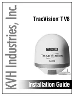
Page 1: ...TracVision TV8 Installation Guide ...
Page 50: ......
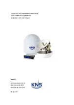
The KVH Industries TracVision TV8 is an advanced satellite TV antenna system that brings the ultimate entertainment experience to your boat or vehicle. Ensure a seamless setup with the user-friendly Installation Manual available for free download from our website, making the installation process a breeze.
Page 1: ...TracVision TV8 Installation Guide ...
Page 50: ......