background image


Ruby3A Industrial Ethernet Switch   

Hardware Installation Manual 


Publication Data: Oct. 2017 

                                        Version: V1.0 

                                        No.

112023101 


Summary of Contents for Ruby3A

Page 1: ...Ruby3A Industrial Ethernet Switch Hardware Installation Manual Publication Data Oct 2017 Version V1 0 No 112023101 ...

Page 2: ...ted as possible This document is not guaranteed to be error free and we reserve the right to amend it without notice to users All rights reserved No part of this documentation may be excerpted reproduced translated annotated or duplicated in any form or by any means without the prior written permission of KYLAND Corporation Copyright 2017 Kyland Technology Co Ltd ...

Page 3: ...als on the device or cables Ensure adequate heat dissipation and tidy cable layout without knots Wear antistatic gloves or take other protective measures when operating the device Avoid any exposed metal wires because they may be oxidized or electrified Install the device in accordance with related national and local regulations Before power on make sure the power supply is within the allowed rang...

Page 4: ... purchase parts from other channels Dispose of the device in accordance with relevant national provisions preventing environmental pollution In the following cases please immediately shut down your power supply and contact your Kyland representative Water gets into the equipment Equipment damage or shell damage Equipment operation or performance has abnormally changed The equipment emits odor smok...

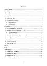
Page 5: ...00Base T X Ethernet Port 11 4 2 1000LX SX 10 100 1000Base T X SFP slot 12 4 2 1 SFP Optical Module 13 4 2 2 SFP Electrical Module 14 4 3 1000LX SX 10 100 1000Base T X Combo Port 15 4 4 Console Port 15 4 5 Grounding 16 4 6 Power Terminal Block 17 4 7 Alarm Terminal Block 19 5 Reset 21 6 LEDs 22 7 Switch Access 23 7 1 Access through Console Port 23 7 2 Access through Telnet 25 7 3 Access through Web...

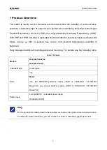
Page 6: ...s occurs and network transmission reliability is improved Ruby3A supports DIN rail mounting and panel mounting For details see the following table Table 1 Models Models Ruby3A 3G L2 L2 Ruby3A 3G HV Code definition Code option Ports 3G Note 3G two HSR PRP ports 2G combo 100FX or 1000LX SX 10 100 1000 Base T X one Access port 1G combo 100FX or 1000LX SX 10 100 1000 Base T X Power input L2 L2 24DCW r...

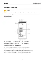
Page 7: ...re 1 Front Panel 1 Power 1 LED 2 Power 2 LED 3 Running LED 4 Operation mode LED 5 Alarm LED 6 Reset button 7 Local port link status 8 Management port 9 10 100 1000Base T X Ethernet Port connection status LED green 10 10 100 1000Base T X Ethernet port speed LED yellow 11 HSR PRP ports 2G combo 100FX or 1000LX SX 10 100 1000 Base T X 12 Local port 1G combo 100FX or 1000LX SX 10 100 1000 Base T X ...

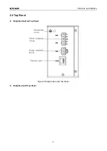
Page 8: ...Structure and Interface 3 2 2 Top Panel Ruby3A 3G L2 L2 Top Panel Figure 2 Ruby3A 3G L2 L2 Top Panel Ruby3A 3G HV Top Panel ...

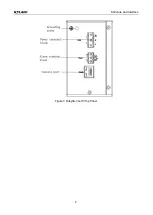
Page 9: ...Structure and Interface 4 Figure 3 Ruby3A 3G HV Top Panel ...

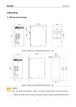
Page 10: ... for DIN Rail Mounting unit mm Figure 5 Dimensions for DIN Rail Mounting unit mm Caution As part of the heat dissipation system the switch housing becomes hot during operation Please use caution when coming in contact and avoid covering the switch housing when the ...

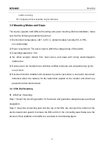
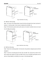
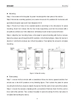
Page 11: ...rence 5 Devices are to be installed in an authority certified enclosure and accessible only by the use of a tool 6 Devices should be installed and accessed by service personnel or users who have been instructed about the reasons for the restrictions applied to the location and about any precautions that shall be taken 3 2 1 DIN Rail Mounting DIN Rail 1 Mounting Step 1 Select the mounting position ...

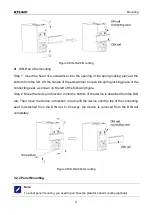
Page 12: ... direction 2 until the device is removed from the DIN rail completely Figure 7 DIN Rail 1 Dismounting DIN Rail 2 Mounting Step 1 Select the mounting position for the device and guarantee adequate space and heat dissipation Step 2 Insert the connecting seat onto the top of the DIN rail and push the bottom of the device inward and upward to ensure the DIN rail fits in the connecting seat Make sure t...

Page 13: ... shown on the left of the following figure Step 2 Move the device in direction 2 until the bottom of the device is detached from the DIN rail Then move the device in direction 3 and uplift the device until the top of the connecting seat is detached from the DIN rail In this way the device is removed from the DIN rail completely Figure 9 DIN Rail 2 Dismounting 3 2 2 Panel Mounting Note To adopt pan...

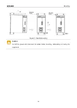
Page 14: ...e plate for panel mounting with the four screws Make the screws pass through the Ф6 5 positions in the following figure Move the device in direction 1 until the four screws are in the Ф4 positions Then tighten the screws to complete mounting Figure 10 Panel Mounting Dismounting Step 1 Loosen the four screws with a screwdriver Move the device upward until the four screws are in the Ф6 5 positions i...

Page 15: ...Mounting 10 Figure 11 Panel Dismounting Caution Cut off the power and disconnect all cables before mounting dismounting or moving the equipment ...

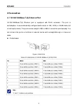
Page 16: ...cross over cable Pin Definition Figure 12 RJ45 Port Table 2 Pin Definitions of 10 100 1000Base T X RJ45 Port Pin MDI X MDI 1 Transmit Receive Data TRD1 Transmit Receive Data TRD0 2 Transmit Receive Data TRD1 Transmit Receive Data TRD0 3 Transmit Receive Data TRD0 Transmit Receive Data TRD1 4 Transmit Receive Data TRD3 Transmit Receive Data TRD2 5 Transmit Receive Data TRD3 Transmit Receive Data TR...

Page 17: ... slot requires an SFP optical electrical module to enable data transmission The following table lists the SFP optical electrical modules optional supported by the series switches Table 3 SFP Optical Electrical Modules Model Port MM SM Connector Central Wavelength Transmission Distance IGSFP M SX LC 850 0 55 1000Base X port MM LC 850nm 0 55km IGSFP S LX LC 1310 10 1000Base X port SM LC 1310nm 10km ...

Page 18: ...ure 14 SFP Optical Module An SFP optical module is equipped with LC connector and each port consists of a TX transmit port and an RX receive port To enable communication between Device A and Device B connect the TX port of Device A to the RX port of Device B and the RX port of Device A to the TX port of Device B as shown in the following figure Figure 15 Fiber Connection of an SFP Optical Module H...

Page 19: ...t one end of the fibers Caution The device uses laser to transmit signals in fibers The laser meets the requirements of level 1 laser products Routine operation is not harmful to your eyes but do not look directly at the fiber port when the device is powered on If the defined transmission distance of an SFP module is longer than 60km do not use a short fiber 20km for connection If such a short fib...

Page 20: ...wisted pair into GX and GE respectively GX can communicate normally and the GE will be disabled automatically The following table lists the relation of Gigabit SFP ports of Combo port and the corresponding 10 100 1000 Base T X Ethernet port Table 4 Combo port corresponding relation Combo port 1000Base X SFP port 10 100 1000Base T X Ethernet port 1 GX1 GE1 2 GX2 GE2 4 4 Console Port The RJ45 connec...

Page 21: ...able Table 5 Pin Definitions of DB9 Port 9 Pin Serial Port and RJ45 Port Console Port DB9 Port 9 Pin Serial Port RJ45 Port Console Port Pin Signal Pin Signal 2 RXD Receive data 2 TXD Transmit data 3 TXD Transmit data 3 RXD Receive data 5 GND Grounding 5 GND Grounding 4 5 Grounding Grounding protects the switch from lightning and interference Therefore you must ground the switch properly You need t...

Page 22: ...to the device The Ruby3A 3G L2 L2 device supports redundant power input with a 5 pin 5 08mm spacing plug in terminal block When one power input is faulty the device can continue operating properly thereby improving network reliability The Ruby3A 3G HV device supports power input with a 3 pin 7 62mm spacing plug in terminal block Note 0 75mm2 Cross sectional area of the power wire 2 5mm2 grounding ...

Page 23: ... of the power wires to the external power supply system according to the power supply requirements of the device View the status of the power LEDs on the front panel If the LEDs are on the power is connected properly Wiring and Mounting should meet following specifications Table 7 Wiring and Mounting Specifications Terminal Type Required Torque Wire Range AWG Terminal Block Plug 4 5 5 0 lb in 12 2...

Page 24: ...Terminal Block Plug 4 5 5 0 lb in 12 24 Caution Before connecting the device to power supply make sure that the power input meets the power requirement If connected to an incorrect power input the device may be damaged Warning Do not touch any exposed conducting wire terminal or component with a voltage warning sign because it may cause damage to humans Do not remove any part or plug in or out any...

Page 25: ...e closed pin 2 and pin 3 are open when an alarm occurs pin 1 and pin 2 are open pin 2 and pin 3 are closed Use copper conductors only temperature rating 85 only Wiring and Mounting Step 1 Remove the alarm terminal block from the switch Step 2 Secure the three wires for alarm into the alarm terminal block in the required sequence Step 3 Insert the alarm terminal block into its socket Wiring and Mou...

Page 26: ... The device provides a Reset button on the front panel The button can be used to restart the device or restore factory default settings You can restart the device by pressing and holding the button for 0 5 to 3 second ...

Page 27: ...s starting up Off The CPU does not start up Alarm LED On An alarm occurs Off No alarm occurs 1000Base FX Ethernet port Gigabit SFP slot connection status LED On Effective port connection Blinking Ongoing network activities Off No effective port connection 10 100 1000Base T X Ethernet port speed LED yellow On 1000M working state 1000Base TX Off 10 100M working state or no connection 10 100 1000Base...

Page 28: ...ection 1000LX SX 10 100 1000Base T X SFP slot port connection status LED On Effective port connection Blinking Ongoing network activities Off No effective port connection 7 Switch Access You can access the switch in any of the following ways 7 1 Access through Console Port Step 1 Connect the console port of the switch to the 9 pin serial port of a PC with the delivered DB9 RJ45 console cable Step ...

Page 29: ...igure 25 Selecting a Serial Port Note To confirm the communication port in use right click My Computer and select Property Click Hardware Device Manager Port to view the communication port Step 5 Set port parameters Bits per second 115200 Data bits 8 Parity None Stop bits 1 and Flow control None as shown in the following figure ...

Page 30: ...how interface vlan 1 Query the default IP address of the switch Privileged mode SWITCH show version Query the version of the switch Privileged mode SWITCH reboot Restart the switch Privileged mode SWITCH set default SWITCH save Restore the factory default settings including the IP address Privileged mode SWITCH config terminal Enter the configuration mode 7 2 Access through Telnet Step 1 Connect t...

Page 31: ...ayed Then you can run the commands in Table 12 to perform operations 7 3 Access through Web Step 1 Connect the network port of a PC to the Ethernet port of the switch with a network cable Step 2 Enter the IP address of the device in the address box of the browser The user login interface is displayed You can log in to the Web UI by default user name admin and password kyland Note Firefox browser i...

Page 32: ...nal block Ruby3A 3G HV 3 pin 7 62mm spacing plug in terminal block Rated Power Consumption Rated power consumption 6 5W MAX Physical Characteristics Housing Metal fanless Protection class IP40 Installation DIN rail mounting or panel mounting Dimensions W H D 66 0mm 135mm 107 5mm excluding the connector DIN rail and component for panel mounting Weight 0 95Kg Environmental Limits Operating temperatu...

Page 33: ...Basic Features and Specifications 28 Warranty five years ...

Page 34: ...FAX 86 10 88796678 Website http www kyland com Email support kyland com For more information about KYLAND products please visit our website http www kyland com ...

Reviews: