background image

SERVICE

MANUAL

Published in September 2016

842NL11B

2NLSM06B

Rev.B

TASKalfa 3010i
TASKalfa 3510i

Summary of Contents for TASKalfa 3010i

Page 1: ...SERVICE MANUAL Published in September 2016 842NL11B 2NLSM06B Rev B TASKalfa 3010i TASKalfa 3510i ...

Page 2: ...TERIE EST REMPLACEE PAR UN MODELE DE TYPE INCORRECT METTRE AU REBUT LES BATTERIES UTILISEES SELON LES INSTRUCTIONS DONNEES Il peut être illégal de jeter les batteries dans des eaux d égout municipales Vérifiez avec les fonctionnaires municipaux de votre région pour les détails concernant des déchets solides et une mise au rebut appropriée Notation of products in the manual For the purpose of this ...

Page 3: ...Control 1 3 119 to 122 Change Procedure of U411 1 3 128 1 3 130 131 Added This setting is usually unnecessary 2 4 1 Correction 1 List of maintenance parts 2 4 3 to 5 Added 3 Periodic maintenance procedures Address Correction 4 20 February 2014 1 1 2 Corection USB host 3 4 1 1 3 Correction Item name change Power source Rated input 1 3 22 Added a comment for the item column of 62 1 3 119 1 3 124 Add...

Page 4: ... 6 Correction Initial values of U034 U051 U140 and U346 1 3 34 Correction Initial values of U034 1 3 38 Correction Maximum scale of initial values of U051 1 3 65 Correction Procedure of U130 1 3 66 Correction Initial values of U140 1 3 69 Correction Initial values of U161 1 3 70 Correction Procedure of U167 Correction Maximum scale of initial values of U198 1 3 113 Correction Procedure of U346 2 2...

Page 5: ...rsonnel to ensure the safety of their customers their machines as well as themselves during maintenance activities Service personnel are advised to read this booklet carefully to familiarize themselves with the warnings and precautions described here before engaging in maintenance activities ...

Page 6: ... this symbol CAUTION Bodily injury or damage to property may result from insufficient attention to or incorrect com pliance with warning messages using this symbol Symbols The triangle symbol indicates a warning including danger and caution The specific point of attention is shown inside the symbol General warning Warning of risk of electric shock Warning of high temperature indicates a prohibited...

Page 7: ...d or dusty place This may cause fire or electric shock Do not install the copier near a radiator heater other heat source or near flammable material This may cause fire Allow sufficient space around the copier to allow the ventilation grills to keep the machine as cool as possible Insufficient ventilation may cause heat buildup and poor copying performance Always handle the machine by the correct ...

Page 8: ... carefully Always check that the copier is correctly connected to an outlet with a ground connection Check that the power cable covering is free of damage Check that the power plug is dust free If it is dirty clean it to remove the risk of fire or electric shock Never attempt to disassemble the optical unit in machines using lasers Leaking laser light may damage eyesight Handle the charger section...

Page 9: ... caution labels that should be present on the machine according to the instruction handbook are clean and not peeling Replace with new ones if necessary Handle greases and solvents with care by following the instructions below Use only a small amount of solvent at a time being careful not to spill Wipe spills off completely Ventilate the room well while using grease or solvents Allow applied solve...

Page 10: ...This page is intentionally left blank ...

Page 11: ... vender option for japan only 1 2 73 1 3 Maintenance Mode 1 3 1 Maintenance mode 1 3 1 1 Executing a maintenance item 1 3 1 2 Maintenance modes item list 1 3 2 3 Contents of the maintenance mode items 1 3 11 1 4 Troubleshooting 1 4 1 Paper misfeed detection 1 4 1 1 Paper misfeed indication 1 4 1 2 Paper misfeed detection component 1 4 3 1 4 2 Self diagnostic function 1 4 13 1 Self diagnostic funct...

Page 12: ... reception 1 4 98 2 10 U044XX error code table Encrypted transmission 1 4 98 1 5 Assembly and disassembly 1 5 1 Precautions for assembly and disassembly 1 5 1 1 Precautions 1 5 1 2 Drum unit 1 5 1 3 Toner 1 5 1 4 How to tell a genuine Kyocera toner container 1 5 2 1 5 2 Outer covers 1 5 3 1 Detaching and refitting the front cover 1 5 3 2 Detaching and refitting the rear cover 1 5 5 3 Detaching and...

Page 13: ...aching and refitting the high voltage PWB 1 5 50 5 Detaching and refitting the ISC PWB 1 5 51 6 Detaching and refitting the operation panel PWB 1 1 5 52 1 5 11 Others 1 5 55 1 Detaching and refitting the language sheet 1 5 55 2 Detaching and refitting the conveying unit 1 5 56 3 Direction of installing the principal fan motors 1 5 58 1 6 Upgrading the firmware 1 6 1 Upgrading the firmware 1 6 1 2 ...

Page 14: ...rocedures 2 4 3 4 Repetitive defects gauge 2 4 6 5 Firmware environment commands 2 4 7 6 System Error Fxxxx Outline 2 4 13 7 Chart of image adjustment procedures 2 4 18 8 Wiring diagram 2 4 21 Installation Guide DP 770 B Document processor DP 772 Document processor DP 773 Document processor PF 791 500 x 2 Paper feeder PF 810 3000 sheet deck DF 791 3000 sheet finisher DF 770 D 1000 sheet finisher A...

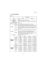
Page 15: ...C4 Envelope C5 Postcards Return postcard Youkei 2 Youkei 4 Custom Zoom level Manual mode 25 to 400 1 increments Auto mode 5R5E Copy speed Without DP Simplex Cassette MP tray Cassette MP tray A4 Letter 30 sheets min 21 sheets min 35 sheets min 24 sheets min A4R LetterR 22 sheets min 17 sheets min 26 sheets min 20 sheets min A3 Ledger 15 sheets min 14 sheets min 17 sheets min 16 sheets min B4 Legal ...

Page 16: ...veloping method Toner replenishing Automatic from the toner container Transfer system Transfer roller method Separation system Small diameter separation dischager brush Cleaning system Counter blade cleaning cleaning roller Charge erasing system Exposure by cleaning lamp LED Fusing system Heat and pressure fusing with the heat roller and the press roller Heat source halogen heater Abnormally high ...

Page 17: ...4 3 8 23 3 8 using MP tray Rated input 120 V AC 60 Hz more than 11 6 A 220 240 V AC 50 60 Hz more than 6 3 A Options Document processor Platen 500x2 paper feeder 3000 sheets deck Document finisher Punch unit Fax kit Expansion memory for Fax Gigabit ethernet board Wireless LAN interface Thin print kit Data security kit Internet FAX kit Card Authentication kit IC card reader holder Document guard ki...

Page 18: ...tterR 13 sheets min 11 sheets min 15 sheets min 12 sheets min A3 Ledger 11 sheets min 10 sheets min 12 sheets min 11 sheets min B4 Legal 11 sheets min 10 sheets min 127 sheets min 11 sheets min B5 30 sheets min 21 sheets min 35 sheets min 24 sheets min B5R 13 sheets min 11 sheets min 15 sheets min 12 sheets min A5R 15 sheets min 15 sheets min 17 sheets min 17 sheets min First print time A4 feed fr...

Page 19: ...peed Simplex B W 80 images min Color 50 images min A4 landscape 300 dpi Image quality Text Photo original Duplex B W 160 images min Color 80 images min A4 landscape 300 dpi Image quality Text Photo original Interface Ethernet 10BASE T 100BASE TX 1000BASE T Network protocol TCP IP Transmission system PC transmission SMB Scan to PC FTP transmission FTP FTP over SSL Scan to FTP E mail transmission SM...

Page 20: ...e front side Figure 1 1 1 7 1 3 2 2 8 4 5 6 6 10 9 1 Cassette 2 Paper width guides 3 Paper length guide 4 MP multi purpose tray 5 MP tray extension 6 MP Paper width guides 7 Inner tray 8 Operation panel 9 USB memory slot 10 Main power switch ...

Page 21: ...4 21 11 Waste toner box 12 Waste toner box Reserve 13 Front cover 14 Right cover 1 15 Right cover 2 16 Transfer roller 17 Feed shift guide 18 Fuser unit 19 Toner container 20 Drum unit 21 Developing unit 22 Toner container lever 23 Developer stopper 24 Developer lever ...

Page 22: ...connect connector cover 26 DP interface connector 27 FAX memory cover 28 Scanner lock cover 29 Coin vender connector 30 Cassette heater switch cover 31 Inlet connector 32 Option interface slot 2 33 Option interface slot 1 34 Network interface connector 35 USB port 36 USB interface connector ...

Page 23: ... key 5 Home key 6 Quick no search key 7 Clear key 8 Reset key 9 Power key 10 Main power indicator 11 Help key 12 Accessibility display key 13 Send key 14 FAX key 15 Job separator indicator 16 Processing indicator 17 Numeric keys 18 Memory indicator 19 Attention indicator 20 Enter key 21 Start key 22 Stop key 23 Interrupt key 24 Authentication Logout key 25 Energy saver key ...

Page 24: ...te 1 2 Cassette 1 paper feed sec tion 3 Cassette 2 4 Cassette 2 paper feed sec tion 5 MP tray paper feed section 6 Conveying section 7 Transfer Separation section 8 Charger roller unit 9 Drum unit 10 Developer unit 11 Toner container 12 Fuser unit 13 Eject section 14 Duplex conveyning section 15 Image scanner unit ISU 16 Laser scanner unit LSU ...

Page 25: ...the environmental temperature and cool or hot direct air Avoid places subject to dust and vibrations Choose a surface capable of supporting the weight of the machine Place the machine on a level surface maximum allowance inclination 1 Avoid air borne substances that may adversely affect the machine or degrade the photoconductor such as mercury acidic of alkaline vapors inorganic gasses NOx SOx gas...

Page 26: ... Print out the user setting list Execution of initial setting operation Execution of mentenance item U952 Set cassette heater control maintenance item U327 Setting the delivery date maintenance item U278 Completion of the machine installation Switch the cassette heater switch Install the other optional devices Clearing the counter maintenance item U927 Output an own status report maintenance item ...

Page 27: ...16 11 7 8 22 21 12 12 17 12 1 Skid 2 Hinge joints 3 Bottom pad RF 4 Bottom pad RR 5 Bottom pad LF 6 Bottom pad LR 7 Bottom pad C 8 Poly bag 9 Accessory box 10 Pad F 11 Pad R 12 Stay 13 Outer case 14 Top pad 15 Machine 16 Poly bag 17 Pad LF 18 Installation guide etc 19 Poly bag 20 DP wire cover 21 Air cap bag 22 Power cord ...

Page 28: ...1 2 3 4 Remove three tapes and the operation unit protection cover 5 Remove the operation panel protection sheet 6 Remove the tape and the desiccant Figure 1 2 4 Remove the tapes and spacer Tape Protection pad Tape Tape Tape Tape Paper Tape Operation panel prptection sheet Tape Desiccant Operation unit protection cover Tape Tape Tape ...

Page 29: ...details Figure 1 2 5 1 Take out the paper preservation bag 2 Pressing the paper width adjusting tab as shown move the paper width guides to fit the paper size Figure 1 2 6 Install the optional paper feeder option Paper feeder Main unit Load paper Cassette Paper width adjusting tab Paper width guides Paper preservation bag ...

Page 30: ...de to fit the paper size Figure 1 2 7 4 Align the paper so that it is abut with the right end of the cassette 5 Insert the cassette size plate 6 Gently push the cassette back in Figure 1 2 8 Paper length guide Paper Cassette Cassette size plate ...

Page 31: ...imes or more Turn the toner container upside down and tap the upper part five times or more Figure 1 2 9 3 Shake the toner container up and down five times or more Turn the toner container upside down and shake it five times or more Figure 1 2 10 Install the toner container Toner container Toner container ...

Page 32: ...tely five or six times in the horizontal direction to stir toner Figure 1 2 11 5 Gently push the toner container into the machine Push the container all the way into the machine until it locks in place Figure 1 2 12 Toner container Toner container CLICK ...

Page 33: ... mode U327 is performed after power activation Enter the maintenance mode by entering 10871087 using the numeric keys Enter 324 using the numeric keys and press the start key Select On or Off Press the start key Press the stop key to exit Precaution for Loading Paper If paper is left in the cassette for a long period heat from the cassette heater may discolor it Switch the cassette heater switch C...

Page 34: ...ar panel Figure 1 2 15 3 Remove the operation panel sheet 4 Replace the operation panel sheet of the corresponding language 5 Refit the clear panel 6 Refit the operation panel covers A and B Figure 1 2 16 Attaching the language label Excluding 240V AC model Operation panel cover A Operation panel cover B Clear panel Operation panel sheet ...

Page 35: ...n Settings Next in Manual Staple Change in Staple Position 3 Select Letter Long Edge 4 Press OK 1 Remove two scanner lock cover using the flatscrew driver 2 Reverse the upper and lower sides of a scanner lock cover and then refit it Releases the lock of the scanner unit If a lock is not released when a power supply is switched on an error mes sage C3100 will be displayed Figure 1 2 17 Install the ...

Page 36: ... state that can be copied 2 The drive chain is disengaged when toner installation is completed 1 Enter the maintenance mode by entering 10871087 using the numeric keys 2 Enter 952 using the numeric keys and press the start key 3 Select Execute 4 Select SETUP 5 Press the start key Running the simulation allows execution histories to be logged The maintenance mode U952 SETUP includes the following I...

Page 37: ...put an own status report maintenance item U000 1 Enter 000 using the numeric keys and press the start key 2 Select Maintenance and press the start key to output a list of the current settings of the maintenance items 3 Press the stop key to exit Clearing the counter maintenance item U927 1 Enter 927 using the numeric keys and press the start key 2 Select Excute 3 Press the start key The counter is...

Page 38: ...t A3 Ledger U260 Selecting the timing for copy counting Eject U265 Setting OEM purchaser code U278 Setting the delivery date U285 Setting service status page On U326 Setting the black line cleaning indication On 8 U327 Set Cassette Heater Control U332 Setting the size conversion factor 1 0 0 1 0 2 5 U340 Setting the applied mode 0 10 U341 Specific paper feed location setting for printing function ...

Page 39: ...2NL 2P8 1 2 15 1 2 3 Option composition DP 770 B DP 772 DF 770 D AK 740 PF 791 PLATEN COVER TYPE E PH 7B DP 773 MT 730 DF 791 PF 810 ...

Page 40: ...NL 2P8 1 2 16 MK 2 Key counter Fax System W Card Authentication kit B MM 16 128 IB 50 DT 730 IB 51 Copy guard kit B Software option Internet FAX Kit A Data Security kit E UG 33 UG 34 Scan extension kit A ...

Page 41: ...ZM610008 H01 Wire saddle C 1 7YZM610009 H01 Parts Quantity Part No Key counter socket assembly 1 3029236241 Key counter cover retainer 1 302GR03010 Key counter retainer 1 302GR03020 Key counter cover 1 3066060011 Key counter mount 1 3066060041 Edging 2 7YZM210006 H01 Band 1 M21AH010 M3 x 8 tap tight P screw 1 5MBTPB3008PW R M4 x 10 tap tight P screw 2 5MBTPB4010PW R M4 x 10 tap tight S screw 2 5MB...

Page 42: ...ote Take out the wire from the central portion of the key counter retainer as shown in a figure 3 Fit the key counter mount to the key counter cover using two screws 4 Fit the key counter retainer to the key counter mount using two screws Figure 1 2 19 M3 x 8 bronze binding screw 1 B1B03080 M4 x 30 tap tight S screw 1 B1B54300 M4 x 6 chrome TP screw 5 B4A04060 M4 x 10 chrome TP screw 2 B4A04100 Pa...

Page 43: ... release three hooks 7 Remove the rear cover Figure 1 2 20 8 Remove two screws and then remove the scanner right cover 9 Remove the right upper cover Figure 1 2 21 Screw Screw Screw Screw Rear cover Hooks Hook Screw Screw Screw Right upper cover Screw Scanner right cover Screw ...

Page 44: ... the aperture plate right side on the right upper cover using nippers Figure 1 2 22 11 Remove two screws and then remove the scanner rear cover Figure 1 2 23 Right upper cover Aperture plate Ribs Screw Scanner rear cover Screw ...

Page 45: ...hooks of the thir 13 Attach the edging to the aperture part Figure 1 2 24 14 Pass the key counter electrical wires through the wire saddle B and the wire saddle C and then pull out from the aperture part Figure 1 2 25 Wire saddle B Wire saddle C Edging Connector Wire saddle B Wire saddle C Aperture Key counter electrical wires ...

Page 46: ...e through the aperture right side in the right upper cover Note Be careful not to put a key coun ter electric wire with the upper right cover 19 Fit the scanner right cover using two screws Figure 1 2 26 20 Insert the projection of the key counter cover retainer in the aperture of the right upper cover 21 Fit the key counter cover retainer using the two M4 x 10 screws Figure 1 2 27 Engine PWB Key ...

Page 47: ...he main power switch on and enter the maintenance mode 27 Run maintenance item U204 and select Key Counter see page P 1 3 80 28 Exit the maintenance mode 29 Check that the message requesting the key counter to be inserted is displayed on the touch panel when the key coun ter is pulled out 30 Check that the counter counts up as copies are made Figure 1 2 28 Key counter cover Key counter elecrtical ...

Page 48: ...Parts Quantity Part No Key counter socket assembly 1 3029236241 Key counter cover retainer 1 302GR03010 Key counter retainer 1 302GR03020 Key counter cover 1 3066060011 Key counter mount 1 3066060041 Edging 2 7YZM210006 H01 Band 1 M21AH010 M3 x 8 tap tight P screw 1 5MBTPB3008PW R M4 x 10 tap tight P screw 2 5MBTPB4010PW R M4 x 10 tap tight S screw 2 5MBTPB4010TW R M3 x 6 bronze flat head screw 2 ...

Page 49: ...entral portion of the key counter retainer as shown in a figure 3 Fit the key counter mount to the key counter cover using two screws 4 Fit the key counter retainer to the key counter mount using two screws Figure 1 2 29 M4 x 10 chrome TP screw 2 B4A04100 Parts Quantity Part No Tray stay 1 Tray mount 1 Tray cover 1 302LC04601 Tray lower cover 1 302LC04710 Tray retainer 1 Sheet 2 302LC04660 Pin 2 3...

Page 50: ...en release three hooks 7 Remove the rear cover Figure 1 2 30 8 Remove two screws and then remove the ISU right cover 9 Remove the right upper cover Figure 1 2 31 Screw Screw Screw Screw Rear cover Hooks Hook Screw Screw Screw Right upper cover Screw Scanner right cover Screw ...

Page 51: ...right upper cover using nippers Note Cut off the rib lower part certainly so that a projection does not remain Figure 1 2 32 11 Remove two screws and then remove the scanner rear cover Figure 1 2 33 Right upper cover Aperture Ribs Rib lower part Screw Scanner rear cover Screw ...

Page 52: ... edging to the aperture part Figure 1 2 34 14 Pass the key counter electrical wires through the wire saddle B and the wire saddle C and then pull out from the aperture part 15 Pass the key counter wire through the edging Figure 1 2 35 Wire saddle B Wire saddle C Edging Connector Wire saddle C Binding band Aperture Wire saddle B Key counter electrical wires ...

Page 53: ... connector of the key counter wire through the aperture right side in the right upper cover Note Be careful not to put a key coun ter electric wire with the upper right cover 20 Fit the scanner right cover using two screws Figure 1 2 36 21 Fit the tray stay to the scanner right cover using two screws Figure 1 2 37 Engine PWB Key counter wires Wire saddle Edgeing Connector Key counter electrical wi...

Page 54: ...2NL 2P8 1 2 30 22 Snap in the tray mount to the tray stay and fix using two screws Figure 1 2 38 M4 8 screw M4 8 screw Tray stay Tray mount ...

Page 55: ... 24 Fit the tray cover to the tray stay using four screws Figure 1 2 39 25 Fit the key counter cover retainer using two screws Figure 1 2 40 M4 x 8 screws Aperture Tray cover Tray cover M4 x 8 screws Key counter cover retainer M4 x 20 tap tight S screw M4 x 20 tap tight S screw ...

Page 56: ...in the document table 27 Fit the key counter cover to the docu ment table using the screw 28 Connect the key counter signal cable to the key counter wire Figure 1 2 41 Aperture Key counter cover Key counter signal cable Key counter signal cable Key counter wire M4 x 6 screw ...

Page 57: ...2NL 2P8 1 2 33 29 Fit the tray lower cover Note Install the key counter signal cable and key counter wire so that they are held behind the tray lower cover Figure 1 2 42 Tray lower cover Connector ...

Page 58: ...et assembly 34 Turn the main power switch on and enter the maintenance mode 35 Run maintenance item U204 and select Key Counter see page P 1 3 80 36 Exit the maintenance mode 37 Check that the message requesting the key counter to be inserted is displayed on the touch panel when the key coun ter is pulled out 38 Check that the counter counts up as copies are made Figure 1 2 44 Pin Tray lower cover...

Page 59: ...key on the operation panel to off Make sure that the power indicator and the memory indicator are off before turning off the main power switch And then unplug the power cable from the wall outlet 2 Remove two pins and then remove the slot cover of the OPT2 Figure 1 2 45 Parts Quantity Part No Gigabit ethernet board 1 1505JV0UN0 option Slot cover Pin Pin OPT2 ...

Page 60: ...ep 2 Caution Do not directly touch the giga bit ethernet board terminal Hold the top and bottom of the gigabit ethernet board or the projection of the board to insert the gigabit ethernet board Figure 1 2 46 4 Plug the modular connector cable into the line terminal Figure 1 2 47 Pin Groove Pin Gigabit ethernet board Modular connector cable ...

Page 61: ...o off Make sure that the power indicator and the memory indicator are off before turning off the main power switch And then unplug the power cable from the wall outlet 2 Remove the staple holder 3 Remove a screw and then remove the staple cover Figure 1 2 48 Parts Quantity Part No IC card reader holder E 1 1709AD0UN1 option Parts Quantity Part No IC card reader holder 1 Label 1 Bundling band 1 Hoo...

Page 62: ...ers depending type of IC card readers Type A Thicker and in the same size as its holder Continue to step 6 Type B Thicker but smaller than its holder Continue to step 8 Type C Thinner and in the same size as its holder Continue to step 11 Figure 1 2 50 Upper cover B Lock part Type A Type B Type C IC card reader ...

Page 63: ...card reader and IC card reader holder 7 Mount the IC card reader to the IC card reader holder Proceed to step 10 Figure 1 2 51 IC card reader Type A IC card reader holder Hook and loop fasteners Hook and loop fasteners IC card reader holder IC card reader Type A ...

Page 64: ...fastener onto the IC card reader so that it is mounted on the holder with both being flush with the right side edges 9 Mount the IC card reader to the IC card reader holder Figure 1 2 52 IC card reader Type B IC card reader holder Hook and loop fasteners Hook and loop fasteners IC card reader holder IC card reader Type B ...

Page 65: ...10 Route the USB cable from the IC card reader through the IC card reader holder ribs wind four timesaround its back and route through another rib Proceed to step 15 Figure 1 2 53 IC card reader holder USB cable Ribs ...

Page 66: ...se side of the spacer where an adhesive tape has been affixed Affix two spacers to the IC card reader 13 Mount the IC card reader to the IC card reader holder Figure 1 2 54 IC card reader Type C IC card reader holder Hook and loop fasteners IC card reader holder IC card reader Type C Spacer Spacer Hook and loop fasteners ...

Page 67: ...ough the ribs at the bottom of the IC card reader holder wind around its back and route through the rib on the left hand side Make sure the cable will have a slack of about 15 cm Figure 1 2 55 About 15 cm IC card reader holder USB cable Rib bottom USB cable Rib left ...

Page 68: ...n the machine Figure 1 2 56 16 For only type A or B of the IC card reader bundle the surplus length of the cable and insert it into the wire holder Note It pushes also into the crevice between a scanner and a cover Figure 1 2 57 IC card reader holder fixing part Hooks IC card reder holder Wire holder Wire guides USB wire ...

Page 69: ... holder is planned to be added connect it to the connector on the far end Figure 1 2 58 18 Affix a label on the upper cover B align ing it with the positioning mark Fix it by matching with a smoke of a dif ferent color Figure 1 2 59 USB wire USB connector Upper cover B Label Positioning mark ...

Page 70: ... cover B by sliding and uniting two projections and two holes Figure 1 2 60 20 Replace the staple cover and the staple holder in their original positions Figure 1 2 61 Upper cover B Projections Holes Screw Staple holder Staple cover ...

Page 71: ...s you need to log in with admin istrator privileges 3 Press Next of Optional Function 4 Select CARD AUTHENTICATION KIT B and press Activate 5 The License Key entry screen is displayed Enter the License Key using the numeric keys and press Official 6 Confirm the product name CARD AUTHENTICATION KIT B and press Yes 7 To use a SSFC card run maintenance mode U222 and set SSFC When the machine has ente...

Page 72: ...ng off the main power switch And then unplug the power cable from the wall outlet 2 Remove the staple holder 3 Remove a screw Figure 1 2 62 Parts Quantity Part No Keyboard holder B 1 1709AF0UN1 option Parts Quantity Part No Upper keyboard holder 1 Lower keyboard holder 1 Upper keyboard cover 1 Lower keyboard cover 1 Cable cover 1 Upper lid 1 Lower lid 1 Hook and loop fastener 2 Bundling band 2 M4 ...

Page 73: ...8 1 2 49 4 Remove a screw Figure 1 2 63 5 Fit the lower keyboard mounting bracket with the machine using the two S Tite screws M4 x 14 Figure 1 2 64 Screw S Tite screws M4 x 14 Lower keyboard mounting bracket ...

Page 74: ...he upper keyboard mounting bracket onto the lower keyboard mount ing bracket using the four S Tite screws M3 x 8 Align them with each other at the mark B Figure 1 2 66 Lower lid Lower lid Hook S Tite screws M3 x 8 A B S Tite screws M3 x 8 Upper keyboard mounting bracket Upper keyboard mounting bracket Lower keyboard mounting bracket S Tite screw M3 x 8 ...

Page 75: ...ioning pins at the bottom of the lower keyboard cover in the holes on the keyboard mounting bracket and slide towards the rear 11 Latch the lower keyboard cover with the upper keyboard mount by the five hooks Figure 1 2 68 Cutaway portion Lower keyboard cover hole hooks hooks hole Upper keyboard mount Lower keyboard cover Positioning pins ...

Page 76: ...racket using the two P Tite screws M3 x 8 Figure 1 2 69 13 Fix the lower keyboard mounting bracket onto the upper keyboard mounting bracket using the two P Tite screws M3 x 8 Figure 1 2 70 Lower keyboard cover P Tite screws M3 x 8 Upper keyboard cover S Tite screws M3 x 8 S Tite screws M3 x 8 ...

Page 77: ...d loop fas teners on the upper keyboard cover Figure 1 2 71 15 Fix the keyboard with the hook and loop fasteners 16 Connect the USB cable with the USB connector on the machine Figure 1 2 72 Hook and loop fasteners Key board USB cable USB connector ...

Page 78: ... Bundle the surplus length of the cable with two bundling bands and hook it on the hook of the upper keyboard cover Figure 1 2 73 18 Slide the upper lid and fix in the machine Figure 1 2 74 Hook Bunding bands Upper lid ...

Page 79: ...n the machine Latch the three hooks at the near end and press the hooks downwards to mate with the holes at the far end Figure 1 2 75 20 Replace the staple holder Figure 1 2 76 Cable cover Hook Hook Hook Cable cover Holes Hole Staple holder ...

Page 80: ...ff before turning off the main power switch And then unplug the power cable from the wall outlet 2 Remove seven screws 3 Pull the rear cover upwards and then release three hooks 4 Remove the rear cover 5 When not using DP junction PWB the following procedures 6 to 11 are fol lowed and when using it Procedure 13 to 20 is performed Figure 1 2 77 Parts Quantity Part No Printed Document Guard Kit B 1 ...

Page 81: ...e copy guard PWB until it clicks in WIthout a DP junction PWB A FFC is used at YC2 serigraphed on MAIN Figure 1 2 78 8 Fix the copy guard PWB by inserting two aperture parts to two hooks and using the screw M3 x 6 Figure 1 2 79 Copy guard PWB YC2 MAIN FFC long Screw Screw Screw Mount plate Screw Screw Copy guard PWB Aperture part Aperture part Hook Hook ...

Page 82: ...hrough the aperture section of the controller box Figure 1 2 80 11 Connect the main circuit PWB with the FFC Main PWB YC34 12 Refit the DP PWB cover and the rear cover Figure 1 2 81 Controller box aperture part FFC Screw Screw DP PWB cover FFC connector Copy guard PWB Main PWB YC34 ...

Page 83: ...it clicks in WIth a DP junction PWB The FFCs is used at YC2 serigraphed on MAIN and YC1 Serigraphed on DP Figure 1 2 82 15 Fix the copy guard PWB by inserting two aperture parts to two hooks and using the screw M3 x 6 Figure 1 2 83 Copy guard PWB YC2 MAIN FFC long Screw Screw Screw Mount plate Screw YC1 DP FFC short Screw Copy guard PWB Aperture part Aperture part Hook Hook ...

Page 84: ...section of the controller box Figure 1 2 84 18 Connect the main circuit PWB with the FFC Main PWB YC34 When DP connection board has already stuck work after removing Refer to Procedure 19 Figure 1 2 85 Controller box aperture part FFC Screw Screw DP PWB cover FFC connector Copy guard PWB Main PWB YC34 ...

Page 85: ...Confirm the settings 1 Turn the main power switch on 2 Press the system menu key then System Network 3 The user authentication dialog is shown if user authentication is not enabled Enter the login user name and the login password then press Login Use an administrator privilege for login 4 Confirm that the Confidential Guard is set to On Screw DP junction PWB Screw FFC connector Copy guard PWB DP j...

Page 86: ...ity Part No Key card MK 2 1 8J272002 option MK 2 mount 1 Supplied with MK 2 M4 x 16 screw 2 Document table 1 1902LC0UN2 option Bushing 1 M1203490 Mount 1 78660130 M3 8 tap tight p screw TP 2 7BB202308H M4 x 20 tap tight S screw 2 7BB100420H Parts Quantity Part No Tray stay 1 Tray mount 1 Tray cover 1 302LC04601 Tray lower cover 1 302LC04710 Tray retainer 1 Sheet 2 302LC04660 Pin 2 303NS24410 M4 nu...

Page 87: ...e rear cover using nippers etc Figure 1 2 88 5 Release the wire saddle and the guide hook and then remove the connector from the DP relay PWB 6 Remove the screw and remove the DP connector mounting plate Figure 1 2 89 Screw Screw Screws Rear cover Hooks Hook Screw Screw Screw Aperture part Screw Guide Hook DP connector mounting plate Wire saddle DP relay PWB Connector ...

Page 88: ...ver Figure 1 2 90 8 Remove five connectors three USB and FFC from the main PWB 9 Remove six wire holders and release the wires and FFC Figure 1 2 91 Screw Screw Screws Screw Screw Screw Screws Screw Controller box cover Wire guide Wire holders Connectors FFC USB FFC Wires ...

Page 89: ...cover upwards and release four hooks 12 Remove the left lower cover Figure 1 2 92 13 Remove six screws and then remove the controller box Figure 1 2 93 Hooks Screw Screw Screw Screw Left lower cover Screw Screw Screw Screw Controller box Screw Screw Screw Screw ...

Page 90: ...nnect the connector of the key card wires to the engine PWB Figure 1 2 94 16 Pass the key card wires through the wire saddles 17 Fix the grounding terminals using the screw Figure 1 2 95 Key card wires Bushing Bandage lid Connector Key card wires Engine PWB Key card wires Engine PWB Screw Wire saddles Grounding terminal ...

Page 91: ...djust the position of the bushing that is passed key card wires through and then fix the bandage lid using two screws Figure 1 2 96 21 Fit the tray stay to the scanner right cover using two M4 10 screws Figure 1 2 97 Key card wires Bushing Bandage lid Screws Screw Screw Screws Rear cover Hooks Hook Screw Screw Screw Scanner right cover M4 10 screw M4 10 screw Tray stay ...

Page 92: ...2NL 2P8 1 2 68 22 Snap in the tray mount to the tray stay and fix using two M4 x 8 screws 1 2 98 M4 8 screw M4 8 screw Tray stay Tray mount ...

Page 93: ...g four M4 x 8 screws Figure 1 2 99 24 Remove the four screws securing the MK 2 cover attach the MK 2 mount to the MK 2 and secure using the four screws Figure 1 2 100 M4 8 screws Tray cover Try stay M4 8 screws MK 2 mount Screws Screws Screws Screws MK 2 MK 2 ...

Page 94: ...1 2 70 25 Fit the MK 2 to the document table using two M4 x 20 tap tight S screws Secure the screws to the location with mark B Figure 1 2 101 MK 2 Document table M4 20 tap tight S screw M4 20 tap tight S screw ...

Page 95: ...2NL 2P8 1 2 71 26 Fit the tray lower cover 27 Secure the tray lower cover with two pins Figure 1 2 102 Tray lower cover Pin Pin ...

Page 96: ...et onto right side of the document table 29 Turn the main power switch on and enter the maintenance mode 30 Run maintenance item U204 and select Key Card see page 1 3 80 31 Exit the maintenance mode Figure 1 2 103 Sheet Document table ...

Page 97: ...y indicator are off before turning off the main power switch And then unplug the power cable from the wall outlet 2 Remove seven screws 3 Pull the rear cover upwards and then release three hooks 4 Remove the rear cover Figure 1 2 104 Parts Quantity Part No Coin vender 1 ACV 1 option Vender wire 1 Supplied with coin vender Vender base 1 M4 x 6 screw 4 M4 8 ground screw 1 Screw Screw Screw Screw Rea...

Page 98: ...moved in step 5 Figure 1 2 106 8 Secure the ground terminal of the vender wire to IF mount with the screw 9 Connect the connector of the vender wire to connector of the vender signal cable Figure 1 2 107 Screw Lid Screw Screw Screw Vender wires IF mount aperture Vender wire connector Screw Grounding terminal Vender wire connector Connector of vendr signal cable IF mount ...

Page 99: ...tor of the vender wire 12 Turn the main power switch on and enter the maintenance mode 13 Run maintenance mode U206 and acti vate Coin vender is installed Continue configuring the coin vender required see page 1 3 83 14 Exit the maintenance mode Figure 1 2 108 signal cable of coin vender Vender wire connector ...

Page 100: ...2NL 2P8 1 2 76 This page is intentionally left blank ...

Page 101: ...001 using the cursor left right keys or numeric keys and press the start key Enter the maintenance item number using the cursor left right keys or numeric keys The selected maintenance item is run Press the stop key Press the start key Start End Maintenance mode is entered The maintenance item is selected Maintenance mode is exited Repeat the same maintenance item Run another maintenance item No N...

Page 102: ...g U024 HDD formatting U025 Firmware Update Security U026 Pulling Backup Data Drive paper feed and paper conveying system U030 Checking the operation of the motors U031 Checking switches and sensors for paper convey ing U032 Checking the operation of the clutches U033 Checking the operation of the solenoids U034 Adjusting the print start timing LSU Out Top LSU Out Left 0 0 0 0 0 0 0 0 0 U035 Settin...

Page 103: ...sting the DP input light luminosity 1 U087 Setting DP reading position modification operation 145 145 145 U089 Outputting a MIP PG pattern U091 Setting the white line correction 112 112 112 75 0 U099 Adjusting original size detection With original mat With document feeder 0 0 0 0 0 20 30 40 20 30 40 20 30 40 50 50 50 50 50 50 50 50 50 0 0 0 0 0 High volt age U100 Adjusting main high voltage Adjust...

Page 104: ...tion Mode1 U148 Setting drum refresh mode 2 U150 Checking sensors for toner U157 Checking the developer drive time 0 U158 Checking the developer count 0 Fuser U161 Setting the fuser control temperature 120 170 180 190 1 1 170 100 U167 Checking the fuser count 0 U198 Set Fuser Phase Control 0 U199 Displaying fuser heater temperature Operation panel and support equipment U200 Turning all LEDs on U20...

Page 105: ...209 Set RTC Real Time Clock Date A4 U221 Setting the USB host lock function Off U222 Setting the IC card type Other U223 Operation panel lock Unlock U224 Panel sheet extension U234 Setting punch destination Inch Europe Metric U237 Setting finisher stack quantity 0 0 U240 Checking the operation of the finisher U241 Checking the operation of the switches of the fin isher U243 Checking the operation ...

Page 106: ...1 0 0 1 0 2 5 U340 Setting the applied mode Adj Memory Adj Max Job 0 10 U341 Specific paper feed location setting for printing function Off Off Off Off U343 Switching between duplex simplex copy mode Off U345 Setting the value for maintenance due indication 0 U346 Selecting Sleep Mode More Enagy Save On Image processing U402 Adjusting margins of image printing 4 0 3 0 3 0 3 9 U403 Adjusting margin...

Page 107: ... C M Y R G B Adjust Original Chart2 DP 85 4 0 0 1 1 52 0 1 3 2 4 21 0 0 5 2 5 55 2 29 7 45 0 45 9 71 2 2 1 86 3 9 8 89 1 45 5 63 2 43 3 48 4 70 6 25 9 23 6 21 3 42 9 15 0 10 0 190 0 15 0 15 0 390 0 U470 Setting the JPEG compression ratio Copy Photo Text Send Photo Text HC PDF BG HC PDF Char System 90 90 90 90 30 40 51 70 90 30 40 51 70 90 30 40 51 70 90 30 40 51 70 90 15 25 90 15 25 90 15 25 90 15...

Page 108: ...Auto Reduct Setting Protocol List On Off U615 Setting system 6 Ledger U620 Setting the remote switching mode One U625 Setting the transmission system 1 Setting Interval Setting Times 2 3 U630 Setting communication control 1 Setting TX Speed Setting RX Speed Setting TX Echo Setting RX Echo 14400bps V17 14400bps 300 75 U631 Setting communication control 2 Setting ECM TX Setting ECM RX Setting CED Fr...

Page 109: ... Out Setting Td Time Out 56 36 69 30 20 80 60 6 U650 Setting modem 1 Setting Reg G3 TX Eqr Setting Reg G3 RX Eqr Setting RX Mdm Level 0dB 0dB 43dBm U651 Setting modem 2 Modem output level DTMF output level main value DTMF output level level difference 11 8 2 U660 Setting the NCU Setting Exchange Setting Dial Tone Setting Busy Tone Setting PBX Setting Setting DC Loop PSTN On On Loop On U670 Outputt...

Page 110: ... counts 0 0 0 0 0 0 0 0 0 0 0 0 0 0 0 U927 Clearing the all copy counts and machine life counts one time only U928 Checking machine life counts 0 U930 Checking clearing the charger roller count U933 Set Maintenance Mode Execute Log U935 Relay board maintenance 0 U942 Setting of deflection for feeding from DP 0 0 0 U952 Maintenance mode workflow U964 Checking of log U969 Checking of toner area code...

Page 111: ...ms to reenter the settings after initialization or replacement Method Outputs the report 1 Press the start key 2 Select the item to be output 3 Select Print 4 Press the start key A list is output When A4 Letter paper is available a report of this size is output If not specify the paper feed location The output status is displayed Display Output list Maintenance List of the current settings of the ...

Page 112: ...ry slot 3 Turn the main power switch on 4 Enter the maintenance item 5 Press the start key 6 Select the item to be send 7 Press the start key Output will be sent to the USB memory Completion Press the stop key The screen for selecting a maintenance item No is displayed Item No Description Display Output list USB Text Sends output data to the USB memory text type USB HTML Sends output data to the U...

Page 113: ...riprions 0501 01 08 01 01 4002 01 08 01 01 0501 01 08 01 01 4002 01 08 01 01 0501 01 08 01 01 4002 01 08 01 01 0501 01 08 01 01 4002 01 08 01 01 0501 01 08 01 01 4002 01 08 01 01 0501 01 08 01 01 4002 01 08 01 01 0501 01 08 01 01 4002 01 08 01 01 0501 01 08 01 01 4002 01 08 01 01 Service Call Log 8 7 6 5 4 3 2 1 Count 1881214 178944 5296 5295 2099 1054 809 30 Service Code 01 6000 01 2100 01 4000 0...

Page 114: ...er type e Paper eject a Cause of paper jam Hexadecimal For details on the case of paper jam refer to Paper Misfeed Detection P 1 4 3 b Detail of paper source Hexadecimal 00 MP tray 01 Cassette 1 02 Cassette 2 03 Cassette 3 paper feeder 04 Cassette 4 paper feeder 05 to 09 Reserved c Detail of paper size Hexadecimal 00 Not specified 01 Monarch 02 Business 03 International DL 04 International C5 05 E...

Page 115: ...nostics errors are logged The total page count at the time of the self diagnostics error Self diagnostic error code See page 1 4 13 Example 01 6000 01 Self diagnostic error 6000 Self diagnostic error code number 10 Maintenance Log Count Item Remembers 1 to 8 of occurrence of replacement If the occurrence of the previous replace ment of toner con tainer is less than 8 all of the occur rences of rep...

Page 116: ... the toner con tainer f Paper jam g Self diagnostic error h Maintenance item replacing Indicates the log counter of paper jams depending on location Refer to Paper Jam Log All instances includ ing those are not occurred are dis played Indicates the log counter of self diag nostics errors depending on cause See page 1 3 14 Example C6000 4 Self diagnostics error 6000 has hap pened four times Indicat...

Page 117: ... 2 1000 Finisher Installed Card Authentication Kit B Installed Installed Installed Installed UG 34 Installed Connected US English Scan extention kit A Not Installed FAX Information Slot1 Slot2 Rings Normal Rings FAX TEL Rings TAD Option DIMM Size 3 3 3 16 MB Print Coverage Average Total K 1 10 Copy K 1 10 Printer K 1 10 FAX K 1 10 Period Last Page Usage Page A4 Letter Conversion 1111111 11 1111111...

Page 118: ...0000 0000000000000000 0000000000000000 0000000000000000 0000000000000000 000000000000 0000000000000000 0000000000000000 0000000000000000 0000000000000000 0000000000000000 0000000000000000 000000000000 0000000000000000 0000000000000000 0000000000000000 0000000000000000 0000000000000000 0000000000000000 000000000000 0000000000000000 0000000000000000 0000000000000000 0000000000000000 0000000000000000...

Page 119: ...nt guard B Installed Not installed 15 Presence or absence of the IC card authentication kit Installed Not Installed Trial 16 Presence or absence of the internet fax kit Installed Not Installed 17 Presence or absence of the data security kit Installed Not Installed 18 Presence or absence of the UG 33 Installed Not Installed 19 Presence or absence of the UG 34 Installed Not Installed 20 Presence or ...

Page 120: ...he engine software version and the date of update 37 RP code Code the main software version and the date of update 38 RP code Code the engine software version and the date of the previous update 39 RP code Code the main software version and the date of the previous update 40 NV RAM version _ 1F3 1225 _ 1F3 1225 a b c d e f a Consistency of the present software version and the database _ underscore...

Page 121: ...assette 4 Cassette 5 Cassette 6 Cassette 7 Duplex Life counter The second line Drum unit K Developer unit K Maintenance kit A Maintenance kit B 51 Panel lock information 0 Off 1 Partial lock 2 Full lock 52 USB information U00 Not installed U01 Full speed U02 Hi speed 53 Paper handling information 0 Paper source unit select 1 Paper source unit 54 Black and white printing double count mode 0 All sin...

Page 122: ...ation 66 Calibration information 67 Calibration information 68 Calibration information 69 Calibration information 70 Calibration information 71 Calibration information 72 RFID information 73 RFID reader writer version infor mation 74 Maintenance information 75 Altitude 0 Standard 1 High altitude 1 2 High altitude 2 76 Charger roller correction 1 to 5 77 Data Sanitization information 78 Toner low s...

Page 123: ...port Method 1 Press the start key 2 Select Mode1 All 3 Press the start key The mirror frame of the scanner returns to the position for transport 4 Turn the main power switch off and on An error code is displayed in case of an initialization error When errors occurred turn main power switch off then on and execute initialization using maintenance item U002 Error codes Item No Description No Descrip...

Page 124: ...ine number Purpose To check or set the machine number Method 1 Press the start key If the machine serial number of engine PWB matches with that of main PWB If the machine serial number of engine PWB does not match with that of main PWB Setting Carry out if the machine serial number does not match 1 Select Execute 2 Press the start key Writing of serial No starts 3 Turn the main power switch off an...

Page 125: ...e mandatory to contain 3 Select New ID Reconfirm 4 Enter a new 8 digit ID on ten keys 0 9 5 Press the start key The setting is set Method Initialize 1 Select Initialize 2 Press the start key ID is initialized Completion Press the stop key The screen for selecting a maintenance item No is displayed Item No Description Display Description New ID Enter a new 8 digit ID New ID Reconfirm Enter a new 8 ...

Page 126: ... incorrect the following are displayed Completion Press the stop key The screen for selecting a maintenance item No is displayed Item No Description Display Description EXpected Displays the expected checksum Result Displays the calculated checksum Execute Perform the self investigation Display Description f001 An expected value file does not exist f002 Reading the expected value file failed f003 ...

Page 127: ...rsion are displayed 2 Change the screen using the cursor up down keys Item No Description Display Description Main Main firmware MMI Operation firmware Panel Main Operation firmware Panel Boot Operation booting Browser Browser firmware Engine Engine firmware Engine Boot Engine booting Scanner Scanner firmware Scanner Boot Scanner booting RFID RFID firmware Dictionary Dictionary software Option Lan...

Page 128: ...ing DF Document finisher firmware DF Boot Document finisher booting PH Punch unit firmware PH Boot Punch unit booting MT Mailbox firmware MT BOOT Mailbox booting Fax APL1 FAX APL1 Fax Boot1 FAX boot1 Fax IPL1 FAX IPL1 Fax APL2 FAX APL2 multi port Fax Boot2 FAX boot multi port Fax IPL2 FAX IPL2 multi port Mode1 Installed application name Mode2 Installed application name Mode3 Installed application ...

Page 129: ...od 1 Press the start key 2 Select Execute 3 Press the start key All data other than that for adjustments due to variations between machines is initialized based on the destination setting 4 Turn the main power switch off and on Allow more than 5 seconds between Off and On An error code is displayed in case of an initialization error When errors occurred turn main power switch off then on and execu...

Page 130: ... 5 Turn the main power switch off and on Allow more than 5 seconds between Off and On U025 Firmware Update Security Description Used to execute FW Update from the USB flash device while Very High is selected in the Secu rity Level settings under the System Menu Purpose Firmware upgrading is initiated by a service person to conduct U025 while a USB flash device is inserted Method 1 Press the start ...

Page 131: ... margins of image printing U952 Maintenance mode workflow U030 Checking the operation of the motors Description Drives each motor Purpose To check the operation of each motor Method 1 Press the start key 2 Select the motor to be operated 3 Press the start key The operation starts 4 To stop operation press the stop key Completion Press the stop key The screen for selecting a maintenance item No is ...

Page 132: ...witch or sensor is detected to be in the ON position the display for that switch or sensor will be 1 Completion Press the stop key The screen for selecting a maintenance item No is displayed Item No Description Display Switches and sensors Regist Registration sensor RS Fuser Eject sensor ES Duplex Duplex sensor DUS FeedDown Tray Full Paper full sensor PFS Job Separator Full JOB paper full sensor J...

Page 133: ...Purpose To check the operation of each solenoid Method 1 Press the start key 2 Select the solenoid to be operated 3 Press the start key The operation starts 4 To stop operation press the stop key Completion Press the stop key The screen for selecting a maintenance item No is displayed Item No Description Display Description Feed1 Paper feed clutch 1 PFCL1 is turned on Feed2 Paper feed clutch 2 PFC...

Page 134: ... Adjustment LSU Out Top 1 Press the system menu key 2 Press the start key to output a test pattern 3 Press the system menu key 4 Select the item to be adjusted Large size 218 mm or more in width of paper Item No Description Display Description LSU Out Top Leading edge registration adjustment LSU Out Left Center line adjustment Display Description Setting range Initial setting Change in value per s...

Page 135: ...menu key 2 Press the start key to output a test pattern 3 Press the system menu key 4 Select the item to be adjusted Item No Description Correct image Output example 1 Output example 2 Leading edge registration 20 1 5 mm U034 U066 P 1 3 43 U071 P 1 3 48 Display Description Setting range Initial setting Change in value per step MPT Paper feed from MP tray 128 to 127 0 0 1 mm Cassette1 Paper feed fr...

Page 136: ...rt key The value is set Caution Check the copy image after the adjustment If the image is still incorrect perform the following adjustments in maintenance mode Completion Press the stop key The screen for selecting a maintenance item No is displayed Item No Description Center line of printing within 0 5 mm Correct image Output example 1 Output example 2 U034 U067 P 1 3 44 U072 P 1 3 50 ...

Page 137: ...n motors Description Drives each fan motor Purpose To check the operation of each fan motor Method 1 Press the start key 2 Select the fan motor to be operated 3 Press the start key The operation starts 4 To stop operation press the stop key Completion Press the stop key The screen for selecting a maintenance item No is displayed Item No Description Display Description Setting range Initial setting...

Page 138: ...ue using the keys or numeric keys For output example 1 increase the value For output example 2 decrease the value The greater the value the larger the deflection the smaller the value the smaller the deflec tion Figure 1 3 6 7 Press the start key The value is set Completion Press the stop key The indication for selecting a maintenance item No appears Item No Description Display Description Setting...

Page 139: ...ress the start key The value is set Completion Press the stop key The indication for selecting a maintenance item No appears Item No Description Display Description Setting range Main Main motor MM speed adjustment 50 to 50 MPT PMT motor speed adjustment 40 to 40 Duplex Duplex motor speed adjustment 50 to 50 Cassette2 Paper feed motor PFM speed adjustment 50 to 50 Feed2 Feed2 motor speed adjustmen...

Page 140: ...si tion should be changed so that shading is possible without being affected by the flaws or stains Setting 1 Press the start key 2 Select Position 3 Change the setting value using the keys or numeric keys Increasing the value moves the shading position toward the machine left and decreasing it moves the position toward the machine right 4 Press the start key The value is set Supplement While this...

Page 141: ...he start key to make a test copy 4 Press the system menu key 5 Select the item to be adjusted Adjustment Main Scan 1 Change the setting value using the keys or numeric keys For copy example 1 increase the value For copy example 2 decrease the value Figure 1 3 7 2 Press the start key The value is set Item No Description U065 main scan ning direction U065 auxiliary scan ning direction Display Descri...

Page 142: ...umeric keys For copy example 1 increase the value For copy example 2 decrease the value Figure 1 3 8 2 Press the start key The value is set Completion Press the stop key The screen for selecting a maintenance item No is displayed Item No Description Original Copy example 1 Copy example 2 ...

Page 143: ...ys For copy example 1 increase the value For copy example 2 decrease the value Figure 1 3 9 7 Press the start key The value is set Caution Check the copy image after the adjustment If the image is still incorrect perform the following adjustments in maintenance mode Completion Press the stop key The screen for selecting a maintenance item No is displayed Item No Description Display Description Set...

Page 144: ...umeric keys For copy example 1 increase the value For copy example 2 decrease the value Figure 1 3 10 7 Press the start key The value is set Caution Check the copy image after the adjustment If the image is still incorrect perform the following adjustments in maintenance mode Completion Press the stop key The screen for selecting a maintenance item No is displayed Item No Description Display Descr...

Page 145: ...when the setting value is decreased 4 Press the start key The value is set 5 Select Black Line 6 Change the setting using the cursor keys or numeric keys 7 Press the start key The value is set 8 Set the original the one which density is known in the DP and press the system menu key 9 Press the start key Test copy is executed 10 Perform the test copy at each scanning position with the setting value...

Page 146: ...keys For copy example 1 increase the value For copy example 2 decrease the value Increasing the value makes the image longer while decreasing the value makes the image shorter Figure 1 3 11 2 Press the start key The value is set Item No Description Display Description Setting range Initial setting Change in value per step Sub Scan F Magnification in the auxiliary scanning direction of CCD first si...

Page 147: ... the value For copy example 2 decrease the value Increasing the setting enlarges the image and decreasing it narrows the image Figure 1 3 12 2 Press the start key The value is set Completion Press the stop key The screen for selecting a maintenance item No is displayed Item No Description Original Copy example 1 Copy example 2 ...

Page 148: ...y 4 Press the system menu key 5 Select the item to be adjusted l Item No Description Display Description Setting range Initial setting Change in value per step Front Head Leading edge registration of CCD first side 32 to 32 0 0 174 mm Front Tail Trailing edge registration of CCD first side 32 to 32 0 0 174 mm Back Head Leading edge registration of CCD second side 32 to 32 0 0 174 mm Back Tail Trai...

Page 149: ...he above adjustment does not optimize the leading edge registration proceed with the follow ing maintenance modes Adjustment Front Tail Back Tail CIS Tail 1 Change the setting value using the keys or numeric keys For copy example 1 increase the value For copy example 2 decrease the value Figure 1 3 14 2 Press the start key The value is set Caution If the first side is adjusted check the second sid...

Page 150: ...e value For copy example 2 decrease the value Figure 1 3 15 7 Press the start key The value is set Caution If the first side is adjusted check the second side and if adjustment is required carry out the adjustment Check the copy image after the adjustment If the image is still incorrect perform the following adjustments in maintenance mode Completion Press the stop key The screen for selecting a m...

Page 151: ... set 5 Select Execute 6 Press the start key Scanning starts under the selected conditions 7 To stop operation press the stop key Item No Description Display Description Scanner Motor Scanner operation Home Position Home position operation Dust Check Dust adhesion check operation with lamp on DP Reading DP scanning position operation Display Operating conditions Setting range Zoom Magnification 25 ...

Page 152: ...s the luminosity correction for scanning originals from the DP Purpose Modify the setting only if a spotted background appears when a bluish original is scanned from the DP Setting 1 Press the start key 2 Change the setting value using the keys or numeric keys Settings 0 No correction 1 Slight correction 2 Medium correction 3 Strong correction 3 Press the start key The value is set Supplement Whil...

Page 153: ...tart key 2 Select the item to be set Setting CCD 1 Select the item to be set 2 Change the value using the or numeric keys Decreasing the setting makes the objects with less density recognized as dusts less dusts becomes detectable Increasing the value allows more dusts to be detected and the cleaning prompts to be dis played more often 3 Press the start key The value is set Method Black Line 1 Sel...

Page 154: ...tem menu key 4 Press the start key A MIP PG pattern is output Completion Press the stop key The screen for selecting a maintenance item No is displayed Item No Description Display PG pattern to be output Purpose Gray scale Gray scale To check the laser scanner unit engine output characteristics Mono 1 Output density 0 To check the drum quality Mono 4 Output density 70 To check the drum quality 256...

Page 155: ...r on the blank or gray band page and vertical white lines appear on the black band in the same position clean the CIS roller and the CIS glass and then repeat white line correction If vertical black lines or vertical white lines appear on both sheets white line correction has been completed normally However the cause of the vertical lines lies in the engine and thus the engine must be checked 8 Pr...

Page 156: ...letion Press the stop key The screen for selecting a maintenance item No is displayed Item No Description blank sheet black band Causes Corrective measures No lines No lines Complete Black lines White lines Dirty CIS roller or CIS glass Clean CIS roller or CIS glass and then perform U091 again Black lines No lines Engine side U091 ends check engine No lines White lines Engine side U091 ends check ...

Page 157: ...etermines the width of the document The original size sensor determines the document is vertical or horizontal The document is detected two times when the DP is installed Item No Description Display Description Data1 Displaying original size sensor transmission data B W Level1 B W LEVEL setting original size sensor threshold value Setting original size judgment time Data2 Displaying original size ...

Page 158: ...tting Original R1 Original threshold value for color R near side 0 to 255 20 50 Original R2 Original threshold value for color R center 0 to 255 30 50 Original R3 Original threshold value for color R far side 0 to 255 40 50 Original G1 Original threshold value for color G near side 0 to 255 20 50 Original G2 Original threshold value for color G center 0 to 255 30 50 Original G3 Original threshold ...

Page 159: ... Setting Set AC Auto Adj 1 Select On or Off Initial setting On 2 Press the start key The setting is set Displaying Set DC Bias 1 The current setting is displayed Item No Description Display Description Adj AC Bias Main charger AC bias for each color Set AC Auto Adj Setting the AC bias auto adjustment Set DC Bias Main charger DC bias for each color Adj DC Bias Additional surface potential Set Charg...

Page 160: ...e or numeric keys lll 3 Press the start key The value is set Displaying Chk Current 1 The current setting is displayed Completion Press the stop key The screen for maintenance item No is displayed Item No Description Display Description Setting range Initial setting DC2 Bias K Main charger DC bias full speed 128 to 127 0 DC2 Bias Half K Main charger DC bias half speed 128 to 127 0 Display Descript...

Page 161: ...cuted copying from an original is available in interrupt copying mode which is activated by pressing the system menu key Completion Press the stop key The screen for selecting a maintenance item No is displayed Item No Description Display Description Setting range Initial setting On Timing On Timing setting 1000 to 1000 0 Off Timing Off Timing setting 1000 to 1000 70 Pre On Timing Pre On Timing se...

Page 162: ... set Completion Press the stop key The screen for selecting a maintenance item No is displayed U110 Checking the drum count Description Displays the drum counts for checking Purpose To check the drum status Method 1 Press the start key The current drum counts is displayed Completion Press the stop key The screen for selecting a maintenance item No is displayed Item No Description Display Descripti...

Page 163: ...e drum drive time is displayed Completion Press the stop key The screen for selecting a maintenance item No is displayed U117 Checking the drum number Description Displays the drum number Purpose To check the drum number Method 1 Press the start key The drum number is displayed Completion Press the stop key The screen for selecting a maintenance item No is displayed Item No Description Display Des...

Page 164: ... count after replacement of the transfer belt unit or transfer roller Also to clear the counts after replacing transfer roller Method 1 Press the start key The current counts of the transfer counter is displayed Clearing 1 Select Clear 2 Press the start key The counter value is cleared Clears only the transfer roller The transfer belt unit is not cleared Completion Press the stop key The screen fo...

Page 165: ...enance item No is displayed U139 Displaying the temperature and humidity outside the machine Description Displays the detected temperature and humidity outside the machine Purpose To check the temperature and humidity outside the machine Method 1 Press the start key The detected temperature are displayed Completion Press the stop key The screen for selecting a maintenance item No is displayed Item...

Page 166: ...he or numeric keys 1 Low 0 Normal 1 Deep 3 Press the start key The value is set 4 Turn the main power switch off and on Allow more than 5 seconds between Off and On Completion Press the stop key The screen for selecting a maintenance item No is displayed Item No Description Display Description Setting range Initial setting Bias Bias setting 120 to 220 170 Clock Clock setting 2600 to 3000 2700 Duty...

Page 167: ... At the preset value 60 they are toner supplies spaced at 600 seconds 3 Press the start key The setting is set Completion Press the stop key The screen for selecting a maintenance item No is displayed U148 Setting drum refresh mode Description Selects the mode used in drum refreshing Purpose Change settings when drum refreshing is too frequently executed Setting 1 Press the start key 2 Select the ...

Page 168: ...yed U157 Checking the developer drive time Description Displays the developerdrive time for checking a figure which is used as a reference when cor recting the toner control Purpose To check the developer drive time after replacing the developer unit Method 1 Press the start key The developer drive time of each color is displayed Completion Press the stop key The screen for selecting a maintenance...

Page 169: ...ry However this mode can be used to prevent curling or creasing of paper or solve a fuser problem on thick paper Setting 1 Press the start key 2 Select the item to be set 3 Change the setting value using the keys or numeric keys 4 Press the start key The value is set Completion Press the stop key The screen for selecting a maintenance item No is displayed Item No Description Display Description K ...

Page 170: ...ecting a maintenance item No is displayed U198 Set Fuser Phase Control Description Changes the fuser phase control Purpose Performs for the change of the fuser phase control Method 1 Press the start key The fuser count is displayed 2 Change the setting value using the keys or numeric keys 3 Press the start key The value is set Completion Press the stop key The screen for selecting a maintenance it...

Page 171: ...0 Turning all LEDs on Description Turns all the LEDs on the operation panel on Purpose To check if all the LEDs on the operation panel light Method 1 Press the start key 2 Select Execute 3 Press the start key All the LEDs on the operation panel light 4 Press the stop key The LEDs turns off Completion Press the stop key The screen for selecting a maintenance item No is displayed Item No Description...

Page 172: ...ize or Check Figure 1 3 17 Method Initialize 1 Press the start key 2 Tap the center of the sign 3 Press the center of the key dis played next Press it using a tool with a fine tip Figure 1 3 18 Item No Description Display Description Initialize Execute the correction of the touch panel display position Check Confirm the display position of touch panel Maintenance Mode Maintenance Mode Active Initi...

Page 173: ...f your fingers Not your fingernails Figure 1 3 20 5 Press the center of two signs dis played next at the same time Figure 1 3 21 Item No Description Press the center of the sign Press it using a tool with a fine tip Press both circles Finalize with both pressed at the same time Press wiit the tips of your fingers NOT your fingernails Press both circles Finalize with both pressed at the same time P...

Page 174: ...ss it using a tool with a fine tip If you cannot proceed to the next step press the Stop key and try again Press the center of the sign Press it using a tool with a fine tip If you cannot proceed to the next step press the Stop key and try again Press the center of the sign Press it using a tool with a fine tip If you cannot proceed to the next step press the Stop key and try again ...

Page 175: ...6 or less respectively If the setting values are not aligned select Initialize and press the Start key to revert to step 1 Figure 1 3 27 Item No Description Initialize completed Initialize Single Tap Check Press the center of the sign Press it using a tool with a fine tip If you need to perform initialization again select Initialize and press the Start key Initialize Multi Tap Check Single Tap Che...

Page 176: ...eck completed is dis played the checking process is com pleted successfully Figure 1 3 30 Item No Description Multi Tap Check Step 1 Press both circles Finalize with both pressed at the same time Press with the tips of your fingers NOT your fingernails Step1 Not completed Step2 Not completed Initialize Multi Tap Check Step 2 Press both circles Finalize with both pressed at the same time Press with...

Page 177: ... key to revert to Multi tap check Figure 1 3 31 Completion Press the stop key The screen for selecting a maintenance item No is displayed Item No Description Multi Tap Check Step 2 Press both circles again Select Multi Tap Check Step 1 and press the Start key to try again from Multi Tap Check Step 1 If you need to perform initialization again select Initialize and press the Start key Press the Sto...

Page 178: ...ost initiated 7 The result of communication will be displayed Refer to the result Method Call Service End 1 Select Execute 2 Press the start key Communication with the host initiated 3 The result of communication will be displayed Refer to the result Result table Completion Press the stop key The screen for selecting a maintenance item No is displayed Item No Description Display Description Init S...

Page 179: ...Description Normal Speed Normal reading 600 dpi High Speed High speed reading Mode Sets the conveying timing verification mode Reset Resets the conveying timing verification data Result Resets the conveying timing verification data Display Description CCD ADP With paper single sided original of CCD CCD RADP With paper double sided original of CCD CIS With paper double sided original of CIS CCD ADP...

Page 180: ...d Initial setting Off 2 Press the start key The setting is set 3 Turn the main power switch off and on Allow more than 5 seconds between Off and On Setting MESSAGE 1 Select the Key Device or Coin Vender 2 Press the start key The setting is set 3 Turn the main power switch off and on Allow more than 5 seconds between Off and On Completion Press the stop key The screen for selecting a maintenance it...

Page 181: ...ow more than 5 seconds between Off and On Setting No Coin Action 1 Select the item Initial setting Off 2 Press the start key The setting is set 3 Turn the main power switch off and on Allow more than 5 seconds between Off and On Item No Description Display Description On Off Config Sets the presence or absence of the coin vender No Coin Action Behavior when change runs out during copying Price Cha...

Page 182: ... Off and On Setting Print 1 Select the item 2 Select the paper size to be set Item No Description Display Description Normal Charge setting Normal AD Charge setting Commercial Print Charge setting Print Apl Charge setting Extended Display Description B W Black White CMY Single color C M Y RGB Single color R G B Full Color Full color Display Description Setting range Initial setting B W CMY RGB Ful...

Page 183: ...letion Press the stop key The screen for selecting a maintenance item No is displayed Item No Description Display Description Setting range Initial setting B W CMY RGB Full Color A3 Ledger A3 Ledger size 0 to 300 10 100 B4 B4 size 0 to 300 10 50 Card Post card 0 to 300 10 30 Other Other 0 to 300 10 50 Display Description Setting range Initial setting Apl1 Expanded charging unit 1 0 to 300 10 Apl2 ...

Page 184: ...on the immediate right the top LED in that line will light 4 When all the keys on the operation panel have been pressed all the LEDs light for up to 10 seconds Completion Press the stop key The screen for selecting a maintenance item No is displayed U209 Set RTC Real Time Clock Date Description Assign a date and time to RTC Purpose Used to assign a date and time to RTC when Maintenance T is displa...

Page 185: ...s set 5 Turn the main power switch off and on Allow more than 5 seconds between Off and On U222 Setting the IC card type Description Sets the type of IC card Purpose To change the type of IC card Setting 1 Press the start key 2 Select the item Initial setting Other 3 Press the start key The setting is set Completion Press the stop key The screen for selecting a maintenance item No is displayed Ite...

Page 186: ...e operation from the system menu Partial Lock 1 Lock the operation 1 from the system menu Partial Lock 2 Lock the operation 2 from the system menu Partial Lock 3 Lock the operation 3 from the system menu Lock Lock the operation from the system menu and job cancel Item Partial Lock 1 Partial Lock 2 Partial Lock 3 Lock Entering maintenance mode Prohibited Prohibited Entering system menu Prohibited P...

Page 187: ...e information Item No Description Display Description Install Installs the image data or the message data UnInstall Restores the original image data or message data Display Description Display area Opening Img Startup screen Entire start display Call Img Service call screen Graphic display area Home Menu Img Home Menu screen Home Menu display area Call Msg Top Service call message 1 Message displa...

Page 188: ...g from sleeping The total size of the files installable is approximately 4 MB Completion Press the stop key The screen for selecting a maintenance item No is displayed U234 Setting punch destination Description Sets the destination of punch unit of 1000 sheet finisher Purpose To be set when installing a different punch unit from the destination of the machine Setting 1 Press the start key 2 Select...

Page 189: ...ge the setting using the keys or numeric keys Initial setting 0 Number of sheets of stack on the internal tray for non staple copying 10 sheets 2 Press the start key The setting is set 3 Turn the main power switch off and on Allow more than 5 seconds between Off and On Item No Description Display Description Main Tray Number of sheets of stack on the main tray Middle Tray Number of sheets of stack...

Page 190: ...eed Middle H DF middle motor DFMM is turned on at high speed Middle L DF middle motor DFMM is turned on at low speed Eject H DF eject motor DFEM is turned on at high speed Eject L DF eject motor DFEM is turned on at low speed Save H DF drum motor DFDRM is turned on at high speed Save L DF drum motor DFDRM is turned on at low speed Tray DF tray motor DFTM is turned on Operating sequences Ascends af...

Page 191: ...ERM drive position 30 sheet stack Eject Unlock 50 DF eject release motor DFERM drive position 50 sheet stack Eject Unlock Fix DF eject release motor DFERM fixed drive position Eject Unlock Full DF eject release motor DFERM full open drive position Punch Punch motor PUM is turned on Punch Move Punch slide motor PUSLM is turned on Display Description Sub Tray DF feedshift solenoid DFFSSOL is turned ...

Page 192: ...er Mail Box Checking the switch and sensor of the mailbox Punch Checking the switch and sensor of the punch unit Display Description Front Cover DF front cover switch DFFCSW MPT 1 DF eject cover switch DFECSW Top Cover DF top cover switch DFTCSW Tray U Limit DF tray sensor 1 DFTS1 Tray HP2 1 DF tray sensor 2 DFTS2 Tray Middle DF tray sensor 3 DFTS3 Tray L Limit DF tray sensor 4 DFTS4 Tray Top DF t...

Page 193: ...l HP DF shift sensor 2 DFSFS2 Shift Unlock HP DF shift release sensor DFSFRS Sub Tray Full DF sub tray full sensor DFSTFS Shift Set DF shift set sensor DFSFSS Display Description Eject MB eject sensor MBES Cover MB cover open close switch MBCOCSW Over Flow1 MB overflow sensor 1 MBOFS1 Over Flow2 MB overflow sensor 2 MBOFS2 Over Flow3 MB overflow sensor 3 MBOFS3 Over Flow4 MB overflow sensor 4 MBOF...

Page 194: ... for selecting a maintenance item No is dis played Item No Description Display Description Feed Motor 1 2 3 DP original feed motor DPOFM is turned on Conv Motor 1 2 DP original conveying motor DPOCM is turned on Rev Motor 1 3 DP switchback motor DPSBM is turned on Lift Motor 1 2 DP lift motor DPLM is turned on Rev Press Sol 1 DP pressure solenoid DPPSOL is turned on Rev Branch Sol 1 DP feedshift s...

Page 195: ...772 3 DP 773 Completion Press the stop key The screen for selecting a maintenance item No is displayed Item No Description Display Description Feed 1 2 3 DP feed sensor DPFS Regist 1 3 DP registration sensor DPRS Timing 1 2 3 DP timing sensor DPTS CIS Head 2 DP CIS sensor DPCS Tray 1 3 DP switchback sensor DPSBS Set 1 2 3 DP original sensor DPOS Longitudinal 1 2 DP original length switch DPOLSW Li...

Page 196: ...od 1 Press the start key 2 Change the message using the cursor up down keys When a message number is entered with the numeric keys and then the start key is pressed the message corresponding the specified number is displayed 3 Change the language using the keys Completion Press the stop key The screen for selecting a maintenance item No is displayed Item No Description ...

Page 197: ...f front rear shift home position Performed when adjustment is lost with the ejected paper Adjusting of front back stapling home position Adjusts the stapling position in the staple mode if the position is not proper Method 1 Press the start key 2 Select the item to set Method Finisher 1 Select the item to set Item No Description Display Description Finisher Adjustment of 1000 sheet finisher and 30...

Page 198: ... the keys or numeric keys If the distance of the position of a punch hole is smaller than the specified value A increase the setting value If the distance is larger than the value A decrease the setting value Figure 1 3 33 3 Press the start key The value is set Item No Description Description Setting range Initial setting Change in value per step Adjustment of registration stop timing 5 to 5 0 0 2...

Page 199: ...des 7 Repeat the above adjustment until paper is properly in position Setting Shift Front HP Shift Tail HP 1 Select Shift Front HP or Shift Tail HP 2 Change the setting value using the keys or numeric keys 3 Press the start key The value is set 4 Press the stop key The screen for selecting a maintenance item No is displayed 5 Enter maintenance mode U240 and select Motor then Sort Test 6 Repeat the...

Page 200: ...ue When staple positions are off toward the rear side of the machine sample 2 decrease the setting value Figure 1 3 35 3 Press the start key The value is set Completion Press the stop key The screen for selecting a maintenance item No is displayed Item No Description Description Setting range Initial setting Change in value per step Adjustment of front and back stapling home position 5 to 5 0 1 mm...

Page 201: ...r selecting a maintenance item No is displayed Item No Description Display Description 2PF Paper feeder Display Description Motor Off PF paper feed motor PFPFM is turned off On PF paper feed motor PFPFM is turned on Device C1 Clutch PF paper conveying clutch 1 PFPCCL1 is turned on C2 Clutch PF paper conveying clutch 2 PFPCCL2 is turned on V Feed Clutch PF paper feed clutch PFPFCL is turned on H Fe...

Page 202: ... Completion Press the stop key The screen for selecting a maintenance item No is displayed When the firmware is upgraded in the field the standard counter value newly added should be set to 150000 Item No Description Display Description Setting range Initial setting M Cnt A Preset values for maintenance cycle kit A 0 to 9999999 600000 M Cnt HT Preset values for automatic grayscale adjustment 0 to ...

Page 203: ...or selecting a maintenance item No is displayed When the firmware is upgraded in the field input the counter value of U901 into the pri mary feed counter If the counter value is larger than 150000 replace the primary feed roller and input 0 Item No Description Display Description Setting range Initial setting M Cnt A Count value for maintenance cycle kit A 0 to 9999999 0 M Cnt B Count value for ma...

Page 204: ...in power switch off and on An error code is displayed in case of an initialization error When errors occurred turn main power switch off then on and execute initialization using maintenance item U252 Error codes Item No Description Display Description Inch Inch North America specifications Europe Metric Metric Europe specifications Asia Pacific Metric Asia Pacific specifications Australia Australi...

Page 205: ... double count Setting 1 Press the start key 2 Select B W 3 Select the count system Initial setting DBL A3 Ledger 4 Press the start key The setting is set Completion Press the stop key The screen for selecting a maintenance item No is displayed Item No Description Display Description B W Count system of black white mode Display Description SGL All Single count for all size paper DBL A3 Ledger Doubl...

Page 206: ...ss the stop key The screen for selecting a maintenance item No is displayed U265 Setting OEM purchaser code Description Sets the OEM purchaser code Purpose Sets the code when replacing the main PWB and the like Setting 1 Press the start key 2 Change the setting value using the numeric keys 3 Press the start key The setting is set 4 Turn the main power switch off and on Allow more than 5 seconds be...

Page 207: ...Completion Press the stop key The screen for selecting a maintenance item No is displayed U285 Setting service status page Description Determines displaying the print coverage report on reporting Purpose According to user request changes the setting Setting 1 Press the start key 2 Select On or Off Initial setting On 3 Press the start key The setting is set Completion Press the stop key The screen ...

Page 208: ... set Setting Black Line Cnt 1 Select Cnt 2 Change the setting value using the keys or numeric keys When setting is 0 the black line cleaning indication is displayed only if the black line is detected 3 Press the start key The value is set Completion Press the stop key The screen for selecting a maintenance item No is displayed Item No Description Display Description Black Line Mode Black line clea...

Page 209: ... in relation to the A4 Letter size The coefficient set here is used to convert the black ratio in relation to the A4 Letter size and to display the result in user simulation Purpose To set the coefficient for converting the black ratio for nonstandard sizes in relation to the A4 Let ter size Setting 1 Press the start key 2 Change the setting using the keys or numeric keys 3 Press the start key The...

Page 210: ...re than 5 seconds between Off and On Supplement The work area for copy is small and it may cause output failure if the values are large Setting Adj Max Job 1 Change the setting using the keys or numeric keys The maximum Printer jobs should be maximum jobs maximum copy jobs 2 Press the start key The value is set Completion Press the stop key The screen for selecting a maintenance item No is display...

Page 211: ...etion Press the stop key The screen for selecting a maintenance item No is displayed U343 Switching between duplex simplex copy mode Description Switches the initial setting between duplex and simplex copy Purpose To be set according to frequency of use set to the more frequently used mode Setting 1 Press the start key 2 Select On or Off Initial setting Off 3 Press the start key The setting is set...

Page 212: ...e maintenance count reaches the set value the message is displayed Purpose To change the time for maintenance due indication Setting 1 Press the start key 2 Select Cnt 3 Change the setting using the keys or numeric keys 4 Press the start key The value is set Completion Press the stop key The screen for selecting a maintenance item No is displayed Item No Description Display Description Setting ran...

Page 213: ...ress the start key The setting is set Completion Press the stop key The screen for selecting a maintenance item No is displayed Item No Description Display Description Timer Sleep Level BAM conformity country setting Auto Sleep Switches AutoSleep function setting Display Description More Enagy Save BAM conformity setting On Sleep mode is disabled Quick Recovery setting is disabled Less Enagy Save ...

Page 214: ... value is set Caution Check the copy image after the adjustment If the image is still incorrect perform the following adjustments in maintenance mode Completion Press the stop key The screen for selecting a maintenance item No is displayed Item No Description Display Description Setting range Initial setting Change in value per step Lead Printer leading edge margin 0 to 10 0 4 0 0 1 mm A Margin Pr...

Page 215: ...7 7 Press the start key The value is set Caution Check the copy image after the adjustment If the image is still incorrect perform the following adjustments in maintenance mode Completion Press the stop key The indication for selecting a maintenance item No appears Item No Description Display Description Setting range Initial setting Change in value per step A Margin Scanner left margin 0 to 10 0 ...

Page 216: ...tting value using the keys or numeric keys Increasing the value makes the margin wider and decreasing it makes the margin narrower Figure 1 3 38 7 Press the start key The value is set Completion Press the stop key The screen for selecting a maintenance item No is displayed Item No Description U402 P 1 3 114 U403 P 1 3 115 U404 Display Description Setting range Initial setting Change in value per s...

Page 217: ...e system menu key 3 Place an original and press the start key to make a test copy 4 Press the system menu key 5 Select Adj Data 6 Change the setting value using the keys or numeric keys For copy example 1 decrease the value For copy example 2 increase the value Figure 1 3 39 7 Press the start key The value is set Completion Press the stop key The screen for selecting a maintenance item No is displ...

Page 218: ...justment is made second time 7 Place the output test pattern 3 as the original Place approximately 20 sheets of white paper on the test pattern 3 and set them 8 Press the start key Adjustment is made third time 9 When normally completed Finish is displayed If a problem occurs during auto adjustment error code is displayed Error codes Completion Press the stop key The screen for selecting a mainten...

Page 219: ... 6 Select the item Select All for normal use Item No Description Display Description Original to be used for adjustment P N Table Chart1 Automatic adjustment in the scanner sec tion chart 1 7505000005 DP FaceUp Chart1 Do not use Automatic adjustment in the DP scanning section first side chart 1 7505000005 DP FaceDown Chart1 Automatic adjustment in the DP scanning section second side chart 1 750500...

Page 220: ...ly enter the target value 1 Set a specified original P N 7505000005 on the DP face up 2 Enter maintenance item U411 3 Select Target 4 Select Auto and press the start key 5 Select DP FaceUp Chart1 6 Select Input 7 Press the start key Auto adjustment starts When automatic adjustment has normally completed OK is displayed If a problem occurs during auto adjustment error code is displayed and operatio...

Page 221: ... the start key Auto adjustment starts When automatic adjustment has normally completed OK is displayed If a problem occurs during auto adjustment error code is displayed and operation stops Should this happen determine the details of the problem and repeat the procedure from the begin ning If the target values are not obtainable automatically manually enter the following target values in the follo...

Page 222: ...ocedure from the begin ning Method DP FaceUp Chart2 1 Set a specified original P N 302AC68243 on the DP Cut the trailing edge of the original Figure 1 3 40 2 Enter maintenance item U411 3 Select Target 4 Select U425 and press the start key 5 Select DP FaceUp Chart2 6 Select INPUT Item No Description Display Description All Executing the all scanner adjustment Input Executing the adjustment for mag...

Page 223: ...art key Auto adjustment starts Matrix 1 Select Matrix 2 Set a specified original P N 303JX57020 on the DP face down 3 Press the start key Auto adjustment starts When ALL is selected the adjustment of Input MTF Gamma and Matrix can be executed at once When adjusting place the three specified originals on the DP face down and then press the start key Set the original 303JX57020 and then place 303JX5...

Page 224: ...or Codes Item No Description Codes Description 01 Black band detection error scanner auxiliary scanning direction leading edge skew 02 Black band detection error scanner main scanning direction far end skew 03 Black band detection error scanner main scanning direction near end skew 03 Black band detection error scanner auxiliary scanning direction trailing edge skew 04 Black band is not detected s...

Page 225: ...nning direction center line error 15 DP main scanning direction skew error 16 Main scanning direction magnification error 17 Service call error 18 DP paper misfeed error 19 PWB replacement error 1a Original error 1b Input gamma adjustment original error 1c Matrix adjustment original error 1d Original for the white reference compensation coefficient error 1e Lab value searching error 1f Lab value c...

Page 226: ...iption Codes Description S001 Black band is not detected main scanning direction far end S002 Black band is not detected main scanning direction near end S003 Black band is not detected auxiliary scanning direction leading edge S004 Black band is not detected auxiliary scanning direction trailing edge S005 Auxiliary scanning direction skew error 1 5 mm or more S006 Main scanning direction skew err...

Page 227: ...ption White Setting the white patch for the original for adjustment Black Setting the black patch for the original for adjustment Gray1 Setting the Gray1 patch for the original for adjustment Gray2 Setting the Gray2 patch for the original for adjustment Gray3 Setting the Gray3 patch for the original for adjustment C Setting the cyan patch for the original for adjustment M Setting the magenta patch...

Page 228: ...t edge to the right edge black belt 2 of the original at F 15 mm from the top edge of black belt 1 5 Enter the values using the cursor left right keys or numeric keys in Dist2 6 Press the start key The value is set 7 Measure the distance from the top edge of black belt 1 to the bottom of black belt 3 of the original at D and E 1 Measure the distance from the top edge of black belt 1 to the bottom ...

Page 229: ...5 patch for the original for adjustment N475 Setting the N475 patch for the original for adjustment N125 Setting the N125 patch for the original for adjustment C Setting the cyan patch for the original for adjustment M Setting the magenta patch for the original for adjustment Y Setting the yellow patch for the original for adjustment R Setting the red patch for the original for adjustment G Settin...

Page 230: ...iginal at D E and F Measurement procedure 1 Measure the distance from the edge to the black belt b of the original at D 35 mm from the left edge E 110 mm from the left edge and F 185 mm from the left edge respec tively 2 Apply the following formula for the values obtained D F 2 E 2 5 Enter the values solved using the keys or numeric keys in Main Scan 6 Press the start key The value is set 7 Measur...

Page 231: ...f the original at B 4 Enter the measured value using the keys or numeric keys in Main Scan 5 Measure the distance from the black belt of leading edge inside to the black belt of trailing edge inside of the original at C 6 Enter the measured value using the keys or numeric keys in Sub Scan 7 Press the start key The value is set Figure 1 3 43 Completion Press the stop key The screen for selecting a ...

Page 232: ...e image quality but lower the image processing speed Method 1 Press the start key 2 Select the item to be set Setting Copy 1 Select the item to be set 2 Select the item to be set 3 Change the setting value using the keys or numeric keys 4 Press the start key The value is set Item No Description Display Description Copy Compression ratio for copying Send Compression ratio for sending System Compres...

Page 233: ...F reduced file size priority Display Description Setting range Initial setting Y1 to Y5 Compression ratio of brightness 1 to 100 30 40 51 70 90 CbCr1 to CbCr5 Compression ratio of color differential 1 to 100 30 40 51 70 90 Display Description Setting range Initial setting Y3 to Y3 Compression ratio of brightness 1 to 100 15 25 90 CbCr3 to CbCr3 Compression ratio of color differential 1 to 100 15 2...

Page 234: ...em is being executed copying from an original is available in interrupt copying mode which is activated by pressing the system menu key Completion Press the stop key The screen for selecting a maintenance item No is displayed Item No Description Display Description Setting range Initial setting Y Compression ratio of brightness 1 to 100 90 CbCr Compression ratio of color differential 1 to 100 90 ...

Page 235: ...arger value lowers the detection sensitivity but decreases the possibility of false detection 2 Press the start key The value is set Setting PDF Rotation 1 Change the setting value using keys or numeric keys Initial setting 0 2 Press the start key The value is set Completion Press the stop key The screen for selecting a maintenance item No is displayed Item No Description Display Description Conf ...

Page 236: ...stination code OEM code is no operation necessary 3 Select Execute 4 Press the start key Data initialization starts To cancel data initialization press the stop key 5 After data initialization ROM version are displayed A ROM version displays three kinds application boot and IPL Destination code list Item No Description Code Destination Code Destination 000 Japan 253 CTR21 European nations 009 Aust...

Page 237: ...ct Execute 4 Press the start key Data initialization starts To cancel data initialization press the back key 5 After data initialization ROM version are displayed A ROM version displays three kinds application boot and IPL U603 Setting user data 1 Description Makes user settings to enable the use of the machine as a fax Purpose To be executed as required Setting 1 Press the start key 2 Select Line...

Page 238: ...ut any ringing 4 Press the start key The value is set Completion Press the stop key The screen for selecting a maintenance item No is displayed U605 Clearing data Description Initializes data related to the fax transmission such as transmission history Purpose To clear the transmission history Method 1 Press the start key 2 Select CLEAR COM REC 3 Press the start key Initialization processing start...

Page 239: ...ity when the data is recorded in the auto reduction mode If the number of excess lines is below the setting those lines are ignored If over the setting the entire data on a page is fur ther reduced so that it can be recorded on the same page 1 Change the setting using the keys or numeric keys Increase the setting if a page received in the reduction mode is over reduced and too much trailing edge m...

Page 240: ... reduced so that it can be recorded on the same page 1 Change the setting using the keys or numeric keys Increase the setting if a page received in the reduction mode is over reduced and too much trailing edge margin is left Decrease it if the received image does not include all transmitted data 2 Press the start key The value is set Completion Press the stop key The screen for selecting a mainten...

Page 241: ... set 1 Change the setting using the cursor left right keys or numeric keys 2 Press the start key The value is set Completion Press the stop key The screen for selecting a maintenance item No is displayed Item No Description Display Description Adj Lines Sets the number of adjustment lines for automatic reduction Adj Lines A4 Sets the number of adjustment lines for automatic reduction when A4 paper...

Page 242: ...set Initial setting Off 2 Press the start key The setting is set Completion Press the stop key The screen for selecting a maintenance item No is displayed Item No Description Display Description Auto Reduct Selects if auto reduction in the auxiliary direction is to be per formed Protocol List Sets the automatic printing of the protocol list Display Description On Auto reduction is performed if the...

Page 243: ... is displayed U620 Setting the remote switching mode Description Sets the signal detection method for remote switching Be sure to change the setting according to the type of telephone connected to the machine Setting 1 Press the start key 2 Select Remort Mode 3 Select the mode Initial setting One 4 Press the start key The setting is set Completion Press the stop key The screen for selecting a main...

Page 244: ...t Setting Interval 1 Change the setting using the keys or numeric keys 2 Press the start key The value is set Setting Times 1 Change the setting using the keys or numeric keys 2 Press the start key The value is set Completion Press the stop key The screen for selecting a maintenance item No is displayed Item No Description Display Description Interval Setting the auto redialing interval Times Sett...

Page 245: ...med of using the DIS or NSF signal When the destination unit has V 34 capability V 34 is selected regardless of the setting 1 Select the setting Initial setting 14400bps 2 Press the start key The setting is set Item No Description Display Description TX Speed Sets the communication starting speed RX Speed Sets the reception speed TX Echo Sets the waiting period to prevent echo problems at the send...

Page 246: ... after a CED signal is received Used when problems occur due to echoes at the receiver 1 Select the setting Initial setting 75 2 Press the start key The setting is set Completion Press the stop key The screen for selecting a maintenance item No is displayed Item No Description Display Description 500 Sends a DCS 500 ms after receiving a DIS 300 Sends a DCS 300 ms after receiving a DIS Display Desc...

Page 247: ...g to the IP Internet Protocol telephone line 1 Select the setting Initial setting On 2 Press the start key The setting is set Setting CED Freq Sets the frequency of the CED signal Used as one of the measures to improve transmission per formance for international communications 1 Select the setting Initial setting 2100 2 Press the start key The setting is set Completion Press the stop key The scree...

Page 248: ...tion times in the fax telephone auto select mode 1 Select the setting Initial setting 2Time 2 Press the start key The setting is set Completion Press the stop key The screen for selecting a maintenance item No is displayed Item No Description Display Description DIS 4Byte Sets the DIS signal to 4 bytes Num OF CNG F T Sets the CNG detection times in the fax telephone auto select mode Display Descri...

Page 249: ...s used 1 Select the setting Initial setting On 2 Press the start key The setting is set Item No Description Display Description V 34 Enables or disables V 34 communication V 34 3429Hz Sets the V 34 symbol speed 3429 Hz DIS 2Res Sets the number of times of DIS signal reception RTN Check Sets the reference for RTN signal output Display Description On V 34 communication is enabled for both transmissi...

Page 250: ...a maintenance item No is displayed U634 Setting communication control 5 Description Sets the maximum number of error bytes judged acceptable when receiving a TCF signal Used as a measure to ease transmission conditions if transmission errors occur Setting 1 Press the start key 2 Select TCF Check 3 Change the setting using the keys or numeric keys 4 Press the start key The value is set Completion P...

Page 251: ...ge the setting using the keys or numeric keys 2 Press the start key The value is set Setting Time Cont 1 Change the setting using the keys or numeric keys 2 Press the start key The value is set Completion Press the stop key The screen for selecting a maintenance item No is displayed Item No Description Display Description Time One Sets the one shot detection time for remote switching Time Cont Set...

Page 252: ...eric keys 2 Press the start key The value is set Setting T1 Time Out Sets the time before receiving the correct signal after call reception No change is necessary for this maintenance item 1 Change the setting using the keys or numeric keys 2 Press the start key The value is set Item No Description Display Description T0 Time Out Sets the T0 time out time T1 Time Out Sets the T1 time out time T2 T...

Page 253: ...fails to receive a call 1 Change the setting using the keys or numeric keys 2 Press the start key The value is set Figure 1 3 44 Ta Tb1 Tb2 time out time Setting Tb1 Time Out In the fax telephone auto select mode sets the time to start sending the ring back tone after receiving a call as a fax machine see figure 1 3 44 In fax telephone auto select mode change the setting when fax reception is unsu...

Page 254: ...ful or a telephone fails to receive a call 1 Change the setting using the keys or numeric keys 2 Press the start key The value is set Setting Td Time Out Sets the length of the time required to determine silent status fax one of the triggers for Tc time check In the TAD mode change the setting when fax reception is unsuccessful or a telephone fails to receive a call Be sure not to set it too short...

Page 255: ...al setting 0dB 2 Press the start key The setting is set Setting Reg G3 RX Eqr 1 Select 0dB 4dB 8dB or 12dB Initial setting 0dB 2 Press the start key The setting is set Setting RX Mdm Level 1 Select 33dBm 38dBm 43dBm or 48dBm using the cursor up down keys Initial setting 43dBm 2 Press the start key The setting is set Completion Press the stop key The screen for selecting a maintenance item No is di...

Page 256: ... Press the start key 2 Select the item to be set 3 Change the setting using the keys or numeric keys 4 Press the start key The setting is set Completion Press the stop key The screen for selecting a maintenance item No is displayed Item No Description Display Description Setting range Sgl LV Modem Modem output level 15 to 0 DTMF LEV CENT DTMF output level main value 15 to 0 DTMF LEV DIFF DTMF outp...

Page 257: ...l tone is detected to check the telephone is off the hook when a fax is connected to a public switched telephone network 1 Select the setting Initial setting On 2 Press the start key The setting is set Item No Description Display Description Exchange Sets the connection to PBX PSTN Dial Tone Sets PSTN dial tone detection Busy Tone Sets busy tone detection PBX Setting Setting for a PBX DC Loop Sets...

Page 258: ...mode to connect an outside call when connected to a PBX According to the type of the PBX connected select the mode to connect an outside call 1 Select the setting Initial setting Loop 2 Press the start key The setting is set Setting DC Loop Sets if the loop current detection is performed before dialing 1 Select the setting Initial setting On 2 Press the start key The setting is set Completion Pres...

Page 259: ... Description Setting List Outputs a list of software switches self telephone number confidential boxes ROM versions and other information Action List Outputs a list of error history transmission line details and other information Self Sts Report Outputs a list of settings in maintenance mode own status report regarding fax transmission only Protocol List Outputs a list of transmission procedures E...

Page 260: ...f backup data Method 1 Press the start key 2 Select the item 3 Press the start key Backup data is cleared 4 When Recovery FAX DIMM or FAX DIMM Clear is selected turn the main power switch off and on Allow more than 5 seconds between Off and On Completion Press the stop key The screen for selecting a maintenance item No is displayed Item No Description Display Description Reservation Clear Clears t...

Page 261: ...Chg 1 Select the item to be set Initial setting Off 2 Press the start key The setting is set Completion Press the stop key The screen for selecting a maintenance item No is displayed Item No Description Display Description FAX Bulk TX fax batch transmission On Off A5 Pt Priority Chg Change of print size priority at the time of small size reception Display Description On Fax batch transmission is e...

Page 262: ...hown only when the optional dual FAX has been installed Setting 1 Press the start key 2 Press PORT SELECT The current setting is displayed in reverse 3 Select the item to be set Initial setting ALL 4 Press the start key The setting is set Completion Press the stop key The screen for selecting a maintenance item No is displayed Supplement The setting must be made after re entering maintenance mode ...

Page 263: ...h bit between 0 and 1 5 Press the start key to set the value Completion Press the stop key The screen for selecting a maintenance item No is displayed List of Software Switches of Which the Setting Can Be Changed Communication control procedure Item No Description No Bit Item 36 7654 Coding format in transmission 3210 Coding format in reception 37 5 33600 bps V34 4 31200 bps V34 3 28800 bps V34 2 ...

Page 264: ...etection pattern 122 7654 Busy tone detection pattern 1 Busy tone detection in automatic FAX TEL switching 125 76543210 Access code registration for connection to PSTN 126 7654 FAX TEL automatic switching ring back tone ON OFF cycle No Bit Item 133 76543210 DTMF signal transmission time 134 76543210 DTMF signal pause time 141 76543210 Ringer detection cycle minimum 142 76543210 Ringer detection cy...

Page 265: ... paper feed device is not installed the corresponding count is not dis played Clearing 1 Select the counts to be cleared Cassette3 and Cassette4 cannot be cleared 2 Select the counts for all and press Clear 3 Press the start key The counter value is cleared Completion Press the stop key The screen for selecting a maintenance item No is displayed Item No Description Display Description MPT MP tray ...

Page 266: ...ayed 2 Change the screen using the cursor up down keys 3 Select the count value for jam code and press Clear The individual counter cannot be cleared 4 Press the start key The counter value is cleared Method Total Cnt 1 Select Total Cnt The total number of jam code by type is displayed 2 Change the screen using the cursor up down keys The total number of jam count cannot be cleared Completion Pres...

Page 267: ...played 2 Change the screen using the cursor up down keys 3 Select the count value for service call code and press Clear The individual counter cannot be cleared 4 Press the start key The counter value is cleared Method Total Cnt 1 Select Total Cnt The total number of service call counts by type is displayed 2 Change the screen using the cursor up down keys The total number of service call count ca...

Page 268: ...is performed due to problems in the cassettes or other sec tions and the related parts are serviced Method 1 Press the start key 2 Press Execute 3 Press the start key to reset partial operation control 4 Turn the main power switch off and on Allow more than 5 seconds between Off and On Item No Description Display Description DP Counts of document processor DF Counts of document finisher Display De...

Page 269: ...is displayed U910 Clearing the print coverage data Description Clears the accumulated data for the print coverage per A4 size paper and its period of time as shown on the service status report Purpose To clear data as required at times such as during maintenance service Method 1 Press the start key 2 Select Execute 3 Press the start key The print coverage data is cleared Completion Press the stop ...

Page 270: ... key The screen for selecting a maintenance item No is displayed Item No Description Display metric Description Display inch Description A3 Paper feed counts for A3 Ledger Paper feed counts for Ledger B4 Paper feed counts for B4 Legal Paper feed counts for Legal A4 Paper feed counts for A4 Letter Paper feed counts for Letter B5 Paper feed counts for B5 Statement Paper feed counts for State ment A5...

Page 271: ...or written in Item No Description Display Description Import Writing data from the USB memory to the machine Export Retrieving from the machine to a USB memory Display Description Depending data Address Book Address book Job Account Job accounting One Touch Information on one touch key Address Book User User managements Job Account Document Box Document box information Job Account User Shortcut Sh...

Page 272: ...ssing error e0200 to e02ff One touch processing error e0300 to e03ff User managements processing error e0400 to e04ff Panel program processing error e0500 to e05ff FAX transmission processing error e0600 to e06ff System setting processing error e0700 to e07ff Network processing error e0800 to e08ff Job accounting processing error e0900 to e09ff Short cut processing error e0a00 to e0aff Job process...

Page 273: ...he screen for selecting a maintenance item No is displayed Item No Description Display Description Main Function Counts of main function Sub Function Counts of sub function Display Description B W Copy Count value of black white copy B W Prn Count value of black white print B W Fax Count value of black white FAX Display Description Simplex Count value of Simplex copy Duplex Count value of Duplex c...

Page 274: ...e 3 Press the start key All copy counts and machine life counts are cleared Completion Press the stop key The screen for selecting a maintenance item No is displayed U928 Checking machine life counts Description Displays the machine life counts Purpose To check the machine life counts Method 1 Press the start key The current machine life counts is displayed Completion Press the stop key The screen...

Page 275: ...acing the charger roller unit Method 1 Press the start key The current counts of the charger roller count for each color is displayed Setting 1 Change the setting value using the keys or numeric keys 2 Press the start key The value is set Clearing 1 Select Clear 2 Press the start key The counts is cleared Completion Press the stop key The screen for selecting a maintenance item No is displayed Ite...

Page 276: ...xport 1 Press the start key 2 Select Execute 3 Press the start key Exports a maintenance log to a USB flash device Execute is grayed out is a USB memory is not installed Displays a OK or NG after execution Setting Setting 1 Select the item Select the key that includes the number you want to configure as the logs are displayed block by block U000 U019 U020 U029 U900 U999 2 Enable or disable the num...

Page 277: ... again when progress of period Setting 1 Press the start key 2 Select Mode using the keys Initial setting Mode0 3 Press the start key The setting is set 4 Turn the main power switch off and on Allow more than 5 seconds between Off and On Supplement After removing the cause of the problem be sure to change the setting in OFF Item No Description Display Description Mode0 Setting mode OFF Mode1 Setti...

Page 278: ...ting value using the keys or numeric keys l 1 Reversed DP only The greater the value the larger the deflection the smaller the value the smaller the deflection If an original non feed jam or oblique feed occurs increase the setting value If wrinkling of original occurs decrease the value 7 Press the start key The value is set Completion Press the stop key The screen for selecting a maintenance ite...

Page 279: ...ance Nbr into a workflow 4 Press the start key The setting is set 5 Press the start key Executes maintenance modes defined in a workflow in succession Item No Description Display Description Continue Restarting an abandoned workflow Execute USB Executes a workflow housed in a USB flash device Execute Executes a workflow stored in the machine Entry USB Exports a workflow housed in a USB flash devic...

Page 280: ...urn the main power switch on 4 Enter maintenance item U952 5 Select Entry USB 6 Select the workflow 7 Select the work flow save area 8 Select Execute Exports a workflow housed in a USB flash device to the machine Example Registration is feasible when a USB flash device that stores the commands and text mainte nance ID editable is inserted File Format xxx mwf 1 SET UP 327 278 000 927 2 WARRANTY 089...

Page 281: ... problem occurs during auto correction error code is displayed Setting Jam Log 1 Select Jam Log 2 Select On or Off 3 Press the start key The setting is set Supplement Instructions on how to obtain a log when the operation panel has frozen Simultaneously press and hold the 8 6 and Clear keys for 3 to 6 seconds to start logging The memory indicator keeps lighting during a log is generated and goes o...

Page 282: ...ter verifying the main power indicator has gone off switch off the main power switch 2 Insert USB memory in USB memory slot 3 Turn the main power switch on 4 Enter maintenance item U977 5 Select Execute 6 Press the start key 7 Send the print data to the machine Once the print data is stored into USB memory Finish will be displayed Completion Press the stop key The screen for selecting a maintenanc...

Page 283: ...ormal operation deactivating the keys Object error C9940 Confidential document guard uninstalled error U984 Checking the developer unit number Description Displays the developer unit number Purpose To check the developer unit number Method 1 Press the start key The developer unit number for each color is displayed Completion Press the stop key The screen for selecting a maintenance item No is disp...

Page 284: ...isk Description Restores data in the hard disk by scanning the disk Purpose If power is turned off while accessing to the hard disk is performed the control information in the hard disk drive may be damaged Use this mode to restore the data Method 1 Press the start key 2 Select Execute 3 Press the start key When scanning of the disk is complete the execution result is displayed 4 Turn the main pow...

Page 285: ...canner Method 1 Press the start key The current operation counts is displayed Completion Press the stop key The screen for selecting a maintenance No item is displayed Item No Description Display Description Copy Scan Scanner operation counts for copying Fax Scan Scanner operation counts for fax Other Scan Scanner operation counts except for copying ...

Page 286: ...2NL 2P8 1 3 186 This page is intentionally left blank ...

Page 287: ...tion panel To remove paper misfed in the machine pull out the cassette open the paper conveying unit or paper conveying cover The positions and the corrective actions are displayed on the touch panel when a paper jam has occurred Figure 1 4 1 JAM Paper jam 02 04 1 Open right cover 1 and remove the paper 2 Open the fuser cover a and remove the paper 3 Remove any paper from the paper ejection 4 Clos...

Page 288: ...sfeed in the MP tray E Misfeed in the duplex unit F Misfeed in the inner tray or fuser section G Misfeed in the document processor option H Misfeed in the job separator I Misfeed in the the bridge option J Misfeed in the the document finisher option K Misfeed in the the mail box option A D G H I B C C B E F C C K J J J J J J J ...

Page 289: ...FMTS MBES TOFSW2 TOFSW3 TOFSW4 TOFSW5 TOFSW6 TOFSW7 MBES PFPS2 PFPS1 PFFS2 PFFS1 PFPCS2 BRCS2 BRCS1 PFFS FS2 FS1 RS DUS ES PFS JPFS MPPS PS1 PS2 PFPS1 PFPS2 DPOS DPPFS DPPFS DPTS DPSBS 3000 sheet Document finisher 500 sheet 2 Paper feeder 3000 sheet Paper feeder Document processor Mail box ...

Page 290: ...inting 0210 Right cover 3 open The right cover 3is opened during printing 0300 Ejection uncompleted An ejection completed error has occurred 0501 No paper feed from cassette 1 The registration sensor RS does not turn on dur ing paper feed from cassette 1 A 0502 No paper feed from cassette 2 Feed sensor 1 FS1 does not turn on during paper feed from cassette 2 Retry 1 times B 0503 No paper feed from...

Page 291: ...oes not turn off during paper feed from cassette 3 B 1514 Feed sensor 1 FS1 does not turn off during paper feed from cassette 4 B 1704 Feed sensor 2 non arrival jam Feed sensor 2 FS2 does not turn on during paper feed from cassette 4 C 1714 Feed sensor 2 stay jam Feed sensor 2 FS2 does not turn off during paper feed from cassette 4 B 2603 PF feed sensor 1 non arrival jam PF conveying sensor 1 PFPC...

Page 292: ...nsor stay jam The eject sensor ES does not turn off during paper feed from cassette 1 H 4212 The eject sensor ES does not turn off during paper feed from cassette 2 H 4213 The eject sensor ES does not turn off during paper feed from cassette 3 H 4214 The eject sensor ES does not turn off during paper feed from cassette 4 H 4218 The eject sensor ES does not turn off during paper feed from the duple...

Page 293: ...ing sensor 1 BRCS1 does not turn off during paper feed from cassette 3 H 4914 The bridge conveying sensor 1 BRCS1 does not turn off during paper feed from cassette 4 H 4918 The bridge conveying sensor 1 BRCS1 does not turn off during paper feed from duplex section H 4919 The bridge conveying sensor 1 BRCS1 does not turn off during paper feed from the MP tray H 5001 Bridge conveying sensor 2 non ar...

Page 294: ...ned during operation 3000 sheet finisher 6021 DF front cover is opened during operation 1000 sheet finisher 6041 DF top cover open DF top cover is opened during operation 1000 sheet finisher 6060 MB cover open MB cover is opened during operation 3000 sheet finisher 6100 DF paper entry sensor non arrival jam DF paper entry sensor DFPES does not turned on even if a specified time has elapsed after t...

Page 295: ...et finisher J 6401 DF tray upper surface sensor DFTUSS does not turn on within specified time of DF middle eject sensor DFMES turning on 1000 sheet finisher J 6410 DF tray upper surface sen sor stay jam DF tray upper surface sensor DFTUSS is not turned off within specified time of its turning on 3000 sheet finisher J 6411 DF tray upper surface sensor DFTUSS is not turned off within specified time ...

Page 296: ...ed on within specified time after driving the DF staple motor DFSTM 3000 sheet finisher J 7001 DF staple sensor DFSTS is not turned on within specified time after driving the DF staple motor DFSTM 1000 sheet finisher J 7800 MB eject sensor non arrival jam MB eject sensor MBES is not turned on even if a specified time has elapsed after the machine eject signal was received K 7810 MB eject sensor st...

Page 297: ...r DPCS does not turn on within specified time of the paper feed starting G 9009 DP original conveying jam 2 Next feed original became the stand by states of paper feed while reading the image G 9010 DP open The DP is opened during original feeding Sensor in the conveying system is on when the power is turned on or the cover is closed G 9011 DP top cover open The DP top cover is opened during origi...

Page 298: ... DPTS does not turned off within the specified time its turning on G 9500 DP switchback sensor non arrival jam DP switchback sensor DPSBS does not turn on within specified time of DP timing sensor DPTS turning on G 9600 DP eject sensor non arrival jam DP eject sensor DPES does not turn on within specified time of DP timing sensor DPTS turning on G 9610 DP eject sensor stay jam DP eject sensor DPES...

Page 299: ...06 Disconnection at Defect is required See page 1 3 168 Code Contents Related parts Check procedures corrective measures 0030 FAX control PWB system error Processing with the fax soft ware was disabled due to a software problem FAX control PWB 1 Turn the main power swtch off and after 5 seconds re mount the FAX controller PWB then turn power on 2 Reinstall the fax software 3 Replace the FAX contro...

Page 300: ...ly Mismatch between writing data and reading data occurs 8 times successively EEPROM Engine PWB 1 Turn the main power swtch off and after 5 seconds then turn power on 2 Check that the EEPROM is peroperly installed on the engine PWB and re install it 3 Replace the engine PWB see page 1 5 44 4 Check the EEPROM and if the data are currupted contact the service support 0160 Backup memory data error en...

Page 301: ...nds then turn power on 2 Confirm that the wiring connector is firmly connected and if necessary con nect the connector all the way in Operation panel PWB 1 YC10 and Main PWB YC12 3 If the wiring is disconnected shorted or grounded replace the wiring 4 Replace the operation panel PWB 1 see page 1 5 52 Main PWB Replace the main PWB see page 1 5 38 0620 FAX image DIMM error 1 The Fax image DIMM has n...

Page 302: ...iring that connects the CIS and the DP controller PWB Wiring that connects the DP main PWB and the main PWB 3 Replace the DP main PWB 4 Replace the main PWB see page 1 5 38 0640 Hard disk error The hard disk cannot be accessed HDD 1 If an abnormal noise is heard from the HDD replace the HDD 2 Check the SATA wiring between the HDD and the main circuit PWB for loose connection disconnection and dama...

Page 303: ...g between the HDD and the main circuit PWB for loose connection disconnection and damages and that it is connected into the correct terminal Main PWB YC1 YC27 3 Replace the SATA cable 4 Execute U024 to initialize FULL the HDD see page 1 3 30 5 If an error is detected after executing U024 replace the HDD Main PWB Replace the main PWB see page 1 5 38 0670 Hard disk overwriting era sure error HDD 1 I...

Page 304: ... enters in disconnec tion mode after the main power switch has been switched on and off and indi cates Maintenance T Battery main PWB 1 Make sure that the back up batteries on the main PWB are not short circuited 2 Reset Maintenance T by executing U906 see page 1 3 168 3 If the same C call is displayed when power is switched on and off replace the back up battery 4 If communication error due to a ...

Page 305: ...e lift base elevating mechanism Check that the cassette base can be manipulated smoothly if not repair or replace Lift motor 1 1 Check that the cassette base has been ascended 2 Check the drive gear can rotate or they are not unusually loaded and if necessary replace 3 Confirm that the wiring connector is firmly connected and if necessary connect the connector all the way in Lift motor 1 and Engin...

Page 306: ...ace 3 Confirm that the wiring connector is firmly connected and if necessary connect the connector all the way in Lift motor 2 and Engine PWB YC16 4 If the wiring is disconnected shorted or grounded replace the wiring 5 Replace the lift motor 2 Lift sensor 2 1 Check that the sensor is correctly positioned 2 Confirm that the wiring connector is firmly connected and if necessary connect the connecto...

Page 307: ... gear can rotate or they are not unusually loaded and if necessary replace 3 Confirm that the wiring connector is firmly connected and if necessary connect the connector all the way in PF Lift motor 1 and PF main PWB 4 If the wiring is disconnected shorted or grounded replace the wiring 5 Replace the PF lift motor 1 PF Lift sensor 1 1 Check that the sensor is correctly positioned 2 Confirm that th...

Page 308: ... gear can rotate or they are not unusually loaded and if necessary replace 3 Confirm that the wiring connector is firmly connected and if necessary connect the connector all the way in PF Lift motor 2 and PF main PWB 4 If the wiring is disconnected shorted or grounded replace the wiring 5 Replace the PF Lift motor2 PF Lift sensor 2 1 Check that the sensor is correctly positioned 2 Confirm that the...

Page 309: ... base has been ascended 2 Check the drive gear can rotate or they are not unusually loaded and if necessary replace 3 Confirm that the wiring connector is firmly connected and if necessary connect the connector all the way in PF Lift motor 1 and PF main PWB 4 If the wiring is disconnected shorted or grounded replace the wiring 5 Replace the PF lift motor1 PF Lift sensor1 1 Check that the sensor is...

Page 310: ... base has been ascended 2 Check the drive gear can rotate or they are not unusually loaded and if necessary replace 3 Confirm that the wiring connector is firmly connected and if necessary connect the connector all the way in PF Lift motor 2 and PF main PWB 4 If the wiring is disconnected shorted or grounded replace the wiring 5 Replace the PF Lift motor2 PF Lift sensor2 1 Check that the sensor is...

Page 311: ...nnected shorted or grounded replace the wiring 3 Replace the PF main PWB Refer to the service manual for the paper feeder Engine PWB 1 Check the engine software and upgrade to the latest if necessary 2 Replace the engine PWB see page 1 5 44 1900 Paper feeder EEPROM error When writing the data read and write data does not match 4 times in succession PF main PWB EEPROM 1 Confirm that the wiring conn...

Page 312: ... the main motor Engine PWB 1 Check the engine software and upgrade to the latest if necessary 2 Replace the engine PWB see page 1 5 44 2010 Main motor startup error Main motor is not stabilized within 1 s since the motor is activated Main motor 1 To check the motor operation execute U030 Main main motor see page 1 3 31 2 Confirm that the wiring connector is firmly connected and if necessary con ne...

Page 313: ...ngine software and upgrade to the latest if necessary 2 Replace the engine PWB see page 1 5 44 2510 Paper feed motor startup error Paper feed motor is not stabi lized within 1 s since the motor is activated Paper feed motor 1 To check the motor operation execute U030 Feed paper feed motor see page 1 3 31 2 Check the paper feed roller and drive gear can rotate or they are not unusually loaded and i...

Page 314: ...Replace the PF main PWB Refer to the service manual for the paper feeder 2610 PF drive motor error large capacity feeder After PF drive motor is driven the ready signal does not turn to L within 2 s PF drive motor 1 To check the feed unit operation exe cute U247 LCF Motor ON see page 1 3 101 2 Check the paper feed roller and drive gear can rotate or they are not unusually loaded and if necessary r...

Page 315: ...ge the wire 4 Confirm that the wiring connector is firmly connected and if necessary connect the connector all the way in Scanner motor and ISC PWB YC5 ISC PWB YC3 and Main PWB YC11 5 If the wiring is disconnected shorted or grounded replace the wiring 6 Replace the scanner motor Home position sensor 1 Check that the sensor is correctly positioned 2 Confirm that the wiring connector is firmly conn...

Page 316: ...SHD PWB DP relay PWB Replace the DP relay PWB 3220 LED error The threshold is calculated for colors at initialization and the pixel which does not exceed that value is greater than 200 It is 1000 or more at the time of market mode CIS 1 Execute CIS of U061 lamp check see page 1 3 40 2 Confirm that the wiring connector is firmly connected and if necessary connect the connector all the way in LED la...

Page 317: ...One of the gains is FF during the CCD lamp AGC is being processed CIS 1 Execute U906 Separating Operation Release see page 1 3 168 2 To check the lamp execute U061 CIS see page 1 3 40 3 Confirm that the wiring connector is firmly connected and if necessary connect the connector all the way in DP CIS and DPSHD PWB YC2 DPSHD PWB YC3 and DP relay PWB YC2 4 If the wiring is disconnected shorted or gro...

Page 318: ...e the ISU and execute U411 see page 1 5 51 3900 Backup memory read write error ISC PWB Read and write data does not match Backup memory ISC PWB 1 Turn the main power switch off and after 5 seconds turn it on 2 Replace the ISC PWB and execute U411 see page 1 5 51 4001 Polygon motor synchroni zation error After polygon motor is driven the ready signal does not turn to L within 10 s Polygon motor LSU...

Page 319: ...connector is not distorted and connect the FCC wiring all the way in BD PWB and APC PWB YC2 APC PWB YC1 and Engine PWB YC27 2 If the FCC wiring is disconnected replace the FCC wiring 3 Replace the laser scanner unit see page 1 5 21 Engine PWB 1 Check the engine software and upgrade to the latest if necessary 2 Replace the engine PWB see page 1 5 44 4201 BD steady state error The BD signal is not d...

Page 320: ...t distorted or adhered with foreign objects 2 Reinstall the chrager roller unit Or replace the charger roller unit see page 1 5 16 High voltage PWB 1 Confirm that the wiring connector is firmly connected and if necessary connect the connector all the way in High voltage PWB CN1 and Engine PWB YC31 2 If the FCC wiring is disconnected shorted or grounded replace the FCC wiring 3 Replace the High vol...

Page 321: ...de to the latest if necessary 2 Replace the engine PWB see page 1 5 44 6030 Broken fuser thermistor 2 wire A D value of the fuser thermis tor 2 exceeds 251 bit continu ously for 5 6 s during warming up Fuser unit 1 Confirm that the wiring connector is firmly connected and if necessary con nect the connector all the way in Fuser thermistor 2 and Fuser PWB YC2 Fuse PWB and Engine PWB YC22 2 If the w...

Page 322: ...ser heater Powe source PWB Replace the power source PWB see page 1 5 49 Engine PWB 1 Check the engine software and upgrade to the latest if necessary 2 Replace the engine PWB see page 1 5 44 6220 Abnormally high fuser edge thermistor temperature Input from fuser thermistor 1 is abnormal value continu ously for 1 s Fuser unit 1 Confirm that the wiring connector is firmly connected and if necessary ...

Page 323: ...e engine PWB see page 1 5 44 6250 Abnormally low fuser edge thermistor temperature When the detection tempera ture of the fixing thermistor 1 is falling target temperature by 75 C or more for 1 second after secondary stable tem perature attainment Fuser unit 1 Confirm that the wiring connector is firmly connected and if necessary connect the connector all the way in Fuser thermistor 1 and Fuser PW...

Page 324: ...ine PWB 1 Turn the main power switch off and after 5 seconds turn it on 2 Reinstall the engine software 3 Replace the engine PWB see page 1 5 44 7200 Broken outer temperature sensor 2 wire The sensor input sampling is greater than 244 BD PWB 1 Confirm External Temp is displayed by U139 temperature and humidity see page 1 3 65 2 Confirm that the wiring connector is firmly connected and if necessary...

Page 325: ...PWB 1 Confirm that the wiring connector is firmly connected and if necessary connect the connector all the way in Thermistor PWB and Engine PWB YC6 2 If the wiring is disconnected shorted or grounded replace the wiring 3 Replace the thermistor PWB Engine PWB 1 Check the engine software and upgrade to the latest if necessary 2 Replace the engine PWB see page 1 5 44 7810 Short circuited external the...

Page 326: ...test if necessary 2 Replace the engine PWB see page 1 5 44 7911 Developer unit EEPROM error No response is issued from the device in reading writing for 5 ms or more and this problem is repeated five times successively Mismatch of reading data from two locations occurs 8 times successively Mismatch between writing data and reading data occurs 8 times successively Developer unit 1 Confirm that the ...

Page 327: ... motor Punch home position sensor 1 Execute U241 Punch Punch HP to check the finisher switch see page 1 3 92 2 Check that the sensor and its mounting bracket are correctly positioned 3 Confirm that the wiring connector is firmly connected and if necessary connect the connector all the way in Punch home position sensor and Punch PWB YC8 4 Replace the Punch home position sensor Punch PWB 1 Confirm t...

Page 328: ...connected and if necessary connect the connector all the way in Punch motor and Punch PWB YC4 5 If the wiring is disconnected shorted or grounded replace the wiring 6 Replace the punch motor Punch PWB 1 Confirm that the wiring connector is firmly connected and if necessary connect the connector all the way in Punch PWB YC1 and DF main PWB YC7 3000 sheet finisher Punch PWB YC1 and DF main PWB YC8 1...

Page 329: ...mly connected and if necessary connect the connector all the way in Punch motor and Punch PWB YC4 5 If the wiring is disconnected shorted or grounded replace the wiring 6 Replace the punch motor Punch PWB 1 Confirm that the wiring connector is firmly connected and if necessary connect the connector all the way in Punch PWB YC1 and DF main PWB YC7 3000 sheet finisher Punch PWB YC1 and DF main PWB Y...

Page 330: ... 1000 sheet finisher 5 If the wiring is disconnected shorted or grounded replace the wiring 6 Replace the DF paddle motor DF paddle sensor 1 Execute U241 Finisher Bundle Eject HP to check the finisher switch see page 1 3 92 2 Check that the sensor and its mounting bracket are correctly positioned 3 Confirm that the wiring connector is firmly connected and if necessary connect the connector all the...

Page 331: ...DF bundle discharge unit sensor and DF main PWB YC20 1000 sheet finisher 5 If the wiring is disconnected shorted or grounded replace the wiring 6 Replace the DF eject release motor DF bundle discharge unit sensor 1 Execute U241 Finisher Bundle Eject HP to check the finisher switch see page 1 3 92 2 Check that the sensor and its mounting bracket are correctly positioned 3 Confirm that the wiring co...

Page 332: ...ctor all the way in DF shift motor 1 front and DF main PWB YC14 5 If the wiring is disconnected shorted or grounded replace the wiring 6 Replace the DF shift motor 1 front DF shift sensor 1 front 1 Execute U241 Finisher Shift Front HP to check the finisher switch see page 1 3 92 2 Check that the sensor and its mounting bracket are correctly positioned 3 Confirm that the wiring connector is firmly ...

Page 333: ...ctor all the way in DF shift motor 2 rear and DF main PWB YC14 5 If the wiring is disconnected shorted or grounded replace the wiring 6 Replace the DF shift motor 2 rear DF shift sensor 2 rear 1 Execute U241 Finisher Shift Tail HP to check the finisher switch see page 1 3 92 2 Check that the sensor and its mounting bracket are correctly positioned 3 Confirm that the wiring connector is firmly conn...

Page 334: ...tor is firmly connected and if necessary connect the connector all the way in DF shift release motor and DF main PWB YC14 5 If the wiring is disconnected shorted or grounded replace the wiring 6 Replace the DF shift release motor DF shift release sensor 1 Execute U241 Finisher Shift Unlock HP to check the finisher switch see page 1 3 92 2 Check that the sensor and its mounting bracket are correctl...

Page 335: ...lace the wiring 6 Replace the DF tray motor DF tray sensor 1 DF tray upper surface sensor 1 Execute U241 Finisher Tray U Limit Tray Top to check the finisher switch see page 1 3 92 2 Check that the sensor and its mounting bracket are correctly positioned 3 Confirm that the wiring connector is firmly connected and if necessary connect the connector all the way in DF tray sensor 1 and DF Main PWB YC...

Page 336: ...place the wiring 6 Replace the DF tray motor DF tray sensor 1 DF tray upper surface sensor 1 Execute U241 Finisher Tray U Limit Tray Top to check the finisher switch see page 1 3 92 2 Check that the sensor and its mounting bracket are correctly positioned 3 Confirm that the wiring connector is firmly connected and if necessary connect the connector all the way in DF tray sensor 1 and DF main PWB Y...

Page 337: ...DF main PWB YC14 1000 sheet finisher 5 If the wiring is disconnected shorted or grounded replace the wiring 6 Replace the DF tray motor DF tray sensor 4 1 Execute U241 Finisher Tray Middle to check the finisher switch see page 1 3 92 2 Check that the sensor and its mounting bracket are correctly positioned 3 Confirm that the wiring connector is firmly connected and if necessary connect the connect...

Page 338: ...ation motor 1 and DF main PWB YC11 1000 sheet finisher 5 If the wiring is disconnected shorted or grounded replace the wiring 6 Replace the DF side registration motor 1 DF side registration sensor 1 1 Execute U241 Finisher Width Front to check the finisher switch see page 1 3 92 2 Check that the sensor and its mounting bracket are correctly positioned 3 Confirm that the wiring connector is firmly ...

Page 339: ...sheet finisher 5 If the wiring is disconnected shorted or grounded replace the wiring 6 Replace the DF side registration motor 1 DF side registration sensor 1 1 Execute U241 Finisher Width Front to check the finisher switch see page 1 3 92 2 Check that the sensor and its mounting bracket are correctly positioned 3 Confirm that the wiring connector is firmly connected and if necessary connect the c...

Page 340: ...gistration motor 2 and DF main PWB YC11 1000 sheet finisher 5 If the wiring is disconnected shorted or grounded replace the wiring 6 Replace the DF side registration motor 2 DF side registration sensor 2 1 Execute U241 Finisher Width tail HP to check the finisher switch see page 1 3 92 2 Check that the sensor and its mounting bracket are correctly positioned 3 Confirm that the wiring connector is ...

Page 341: ...otor 2 and DF main PWB YC11 1000 sheet finisher 5 If the wiring is disconnected shorted or grounded replace the wiring 6 Replace the DF side registration motor 2 DF side registration sensor 2 1 Execute U241 Finisher Width tail HP to check the finisher switch see page 1 3 92 2 Check that the sensor and its mounting bracket are correctly positioned 3 Confirm that the wiring connector is firmly conne...

Page 342: ...sher 5 If the wiring is disconnected shorted or grounded replace the wiring 6 Replace the DF slide motor DF staple sensor 1 Execute U241 Finisher Width Staple HP to check the finisher switch see page 1 3 92 2 Check that the sensor and its mounting bracket are correctly positioned 3 Confirm that the wiring connector is firmly connected and if necessary connect the connector all the way in DF staple...

Page 343: ...n PWB Replace the DF main PWB Refer to the service manual for the document finisher 8240 DF staple motor error 2 Staple JAM DF has been detected twice in a row The second JAM detection condition fullfilled with a lock detection signal maintained 1 V for 500 ms continuously while the stapler motor was driven DF staple motor 1 Remove the staple unit and check that stapling is possible without a jam ...

Page 344: ...ted shorted or grounded replace the wiring 5 Replace the DF middle motor DF middle sensor 1 Execute U241 Finisher Middle Tray Eject to check the finisher switch see page 1 3 92 2 Check that the sensor and its mounting bracket are correctly positioned 3 Confirm that the wiring connector is firmly connected and if necessary connect the connector all the way in DF middle sensor and DF main PWB YC20 4...

Page 345: ...d or grounded replace the wiring 6 Replace the punch slide motor Punch slide sensor 1 Execute U241 Punch Punch HP to check the finisher switch see page 1 3 92 2 Check that the sensor and its mounting bracket are correctly positioned 3 Confirm that the wiring connector is firmly connected and if necessary connect the connector all the way in Punch slide sensor and Punch PWB YC6 4 Replace the punch ...

Page 346: ...the wiring 6 Replace the punch slide motor Punch paper edge sensor 1 2 1 Execute U241 Punch Edge Face 1 2 3 4 to check the finisher switch see page 1 3 92 2 Check that the sensor and its mounting bracket are correctly positioned 3 Confirm that the wiring connector is firmly connected and if necessary connect the connector all the way in Punch paper edge sensor 1 2 and Punch PWB YC5 YC7 4 Replace t...

Page 347: ...d shorted or grounded replace the wiring 4 Replace the MB main PWB DF main PWB Replace the DF main PWB 8510 MB conveying motor error 1 3000 sheet finisher When initial operation MB home position sensor does not turn on within 5 s MB conveying motor 1 If the transfer roller won t rotate smoothly repair its mechanism 2 Confirm that the wiring connector is firmly connected and if necessary connect th...

Page 348: ...at the sensor and its mounting bracket are correctly positioned 3 Confirm that the wiring connector is firmly connected and if necessary connect the connector all the way in MB home position sensor and MB main PWB YC2 4 Replace the MB home position sensor MB main PWB Replace the MB main PWB 8800 Document finisher main program error Document finisher main pro gram error at power up DF main PWB 1 Co...

Page 349: ... and if necessary connect the connector all the way in DF main PWB YC4 and Engine PWB YC18 3000 sheet finisher DF main PWB YC7 and Engine PWB YC18 1000 sheet finisher 2 If the wiring is disconnected shorted or grounded replace the wiring DF main PWB Replace the DF main PWB Refer to the service manual for the document finisher Engine PWB Replace the engine PWB see page 1 5 44 9000 Document processo...

Page 350: ...for the rise at job start and two for the irregular rise during transpot ing The accumulated number must be cleared at completion of a normal rise The default threshold is 5 DP lift motor 1 Execute U906 Separating Operation Release see page 1 3 168 2 Execute U243 Lift Motor to check the DP motor operation see page 1 3 94 3 Check that the original document lift guide can move upwards 4 Confirm that...

Page 351: ...onnector is firmly connected and if necessary connect the connector all the way in DP lift sensor 2 and DP main PWB YC2 4 Replace the DP lift sensor2 DP main PWB Replace the DP main PWB 9060 DP EEPROM error Mismatch of reading data from two locations occurs 3 times successively Mismatch between writing data and reading data occurs 3 times successively DP main PWB 1 Execute U906 Separating Operatio...

Page 352: ...B Replace the coin mec 9110 Coin vender rejector error Communication error has been detected in connection with the coin mec and the rejector Rejector 1 Check that the rejector is firmly installed and if not install firmly 2 Replace the rejector 9120 Sensor error in coin vender change Yen 10 Change is empty despite change is enough Coin jam in the change tube Check visually and remedy Contact in t...

Page 353: ...ut error Coin is paid out despite the pay out motor is determined not active Pay out motor Replace the coin mec 9170 Coin vender pay out sensor error Coin is paid out despite the pay out motor is determined not active Pay out area Check no exchange jam is observed at the outlet and if necessary repair it Pay out motor Replace the coin mec Pay out sensor Replace the coin mec 9500 ISC PWB error A Ma...

Page 354: ...ness is not correctly connected Confidential document guard PWB 1 Replace the confidential document guard PW 2 Replace the main PWB see page 1 5 38 F000 Communication error between main PWB and operation PWB Main PWB 1 Turn the main power swtch off and after 5 seconds then turn power on 2 Check that the wirings and connetors between the main circuit PWB and the operation circuit PWB and between th...

Page 355: ...YC3 and the engine PWB YC46 is normal and if necessary re insert Or replace the FCC wire 4 If not corrected replace the main PWB see page 1 5 38 Engine PWB 1 Check the engine software and upgrade to the latest if necessary 2 Replace the engine PWB see page 1 5 44 HDD Replace the HDD F041 Communication error between Main PWB and Scanner engine Main PWB 1 Turn the main power swtch off and after 5 se...

Page 356: ...ROM checksum error Scanner software Install the latest scanner software ISC PWB 1 Turn the main power swtch off and after 5 seconds then turn power on 2 Confirm that the EEPROM has been properly installed 3 If not corrected Replace the ISC PWB Code Contents Related parts Check procedures corrective measures ...

Page 357: ... horizon tally 8 One side of the print image is darker than the other 9 Spots are printed 10 Image is blurred See page 1 4 74 See page 1 4 74 See page 1 4 74 See page 1 4 75 See page 1 4 75 11 The leading edge of the image is con sistently mis aligned with the original 12 The leading edge of the image is spo radically mis aligned with the original 13 Paper is wrin kled 14 Offset occurs 15 Part of ...

Page 358: ...ce the engine PWB see page 1 5 44 No LSU laser is out put Defective laser scanner unit Replace the laser scanner unit see page 1 5 21 Defective main PWB Replace the main PWB see page 1 5 38 Print example Causes Check procedures corrective measures No main charging Defective connector cable or poor contact in the con nector Reinsert the connector Also check for conti nuity within the connector cabl...

Page 359: ...heck procedures corrective measures Defective main charger out put Defective connector cable or poor contact in the con nector Reinsert the connector Also check for conti nuity within the connector cable If none replace the cable High voltage PWB and engine PWB YC31 Defective high voltage PWB Replace the high voltage PWB see page 1 5 50 Defective engine PWB Replace the engine PWB see page 1 5 44 D...

Page 360: ...rum unit see page 1 5 16 Defective transfer roller Replace the transfer roller see page 1 5 17 Dirty scanner mirror Clean the scanner mirror Print example Causes Check procedures corrective measures Dirty or flawed drum Perform the drum refresh operation Flawed drum Replace the drum unit see page 1 5 16 Dirty developer section Clean any part contaminated with toner in the developer section Poor co...

Page 361: ...t example Causes Check procedures corrective measures Scanner moves erratically Check if there is any foreign matter on the front and rear scanner rails If any remove it Deformed press roller Replace the fuse unit see page 1 5 18 Paper conveying section drive problem Check the gears and belts and if necessary grease them Print example Causes Check procedures corrective measures Misadjusted leading...

Page 362: ...es of paper Check if the paper meets specifications Replace paper Print example Causes Check procedures corrective measures Paper damp Check the paper storage conditions Paper creased Replace the paper Drum condensation Perform the drum refresh operation Dirty or flawed drum Perform the drum refresh operation Flawed drum Replace the drum unit see page 1 5 16 Dirty transfer roller Clean the transfe...

Page 363: ...e 1 5 22 Drum condensation Perform the drum refresh operation Print example Causes Check procedures corrective measures Misadjusted image center line Run maintenance item U034 to readjust the center line of image printing see page 1 3 34 Misadjusted scanner center line Run maintenance item U067 to readjust the scanner lead ing edge registration see page 1 3 44 Original is not placed cor rectly Pla...

Page 364: ...r Reinsert the connector Also check for continuity within the connector cable If none replace the cable Eject motor and engine PWB YC3 2 Defective drive trans mission system Check if the rollers and gears rotate smoothly If not grease the bushes and gears Check for broken gears and replace if any 3 Defective motor Replace the eject motor 4 Defective PWB Replace the engine PWB and check for correct...

Page 365: ... Defective motor Replace the ISU motor 4 Defective PWB Replace the ISC PWB and check for correct operation see page 1 5 51 8 Paper feed clutch 1 2 does not oper ate 1 Defective connector cable or poor con tact in the connector Reinsert the connector Also check for continuity within the connector cable If none replace the cable Paper feed clutch 1 and engine PWB YC14 Paper feed clutch 2 and engine ...

Page 366: ...id Replace the Feedshift solenoid 3 Defective PWB Replace the engine PWB and check for correct operation see page 1 5 44 14 The message requesting paper to be loaded is shown when paper is present on the cas sette 1 2 1 Defective connector cable or poor con tact in the connector Reinsert the connector Also check for continuity within the connector cable If none replace the cable Paper sensor and e...

Page 367: ...orrect operation see page 1 5 44 17 A paper jam in the paper feed paper conveying or eject section is indi cated when the main power switch is turned on 1 A piece of paper torn from paper is caught around registration sensor duplex sen sor feed sensor or eject sensor Check visually and remove it if any 2 Defective sensor Replace the registration sensor duplex sensor feed sensor or eject sensor 18 ...

Page 368: ...feed Paper width guide in a cassette installed incorrectly Check the paper width guide visually and remedy or replace if necessary 4 Multiple sheets of paper are fed Check if the paper is excessively curled Change the paper Paper is loaded incorrectly Load the paper correctly Check if the retard roller is worn Replace the retard roller if it is worn see page 1 5 9 1 5 10 5 Paper jams Check if the ...

Page 369: ... shared 1103 Destined host folder and or file names are invalid 1 Check illegal characters are not contained within these names 2 Check the name of the folder and files conform with the naming syntax 3 Confirm destined host and folder 1105 SMB protocol is not enabled 1 Confirm device s SMB protocols 2101 Login to the host has failed 1 Confirm the destined host 2 Confirm that the LAN cable is prope...

Page 370: ...port number 4 Confirm device s network parameters 5 Confirm the network parameters the device is con nected 6 Check the FTP server name 2102 Access to the FTP server has failed Connection timeout 1 Check the FTP server name 2 Check the FTP port number 3 Confirm device s network parameters 4 Confirm the network parameters the device is con nected 5 Check the FTP server name 2103 The server cannot e...

Page 371: ...evice s network parameters 2 Confirm the network parameters the device is con nected 3101 FTP server responded with an error 1 Confirm device s network parameters 2 Confirm the network parameters the device is con nected 3 Check the FTP server Code Contents Check procedures corrective measures ...

Page 372: ...e SMTP POP3 server 2102 Connection to the SMTP POP3 server has failed Connection timeout 1 Check the SMTP POP3 server name 2 Check the SMTP POP3 port number 3 Confirm device s network parameters 4 Confirm the network parameters the device is con nected 5 Check the SMTP POP3 server 2103 The server cannot establish communi cation 1 Check the SMTP POP3 server name 2 Check the SMTP POP3 port number 3 ...

Page 373: ... services including CRAM MD5 DIGEST MD5 PLAIN and LOGIN 4803 Failed to establish the SSL session 1 Verify the self certificate of the device 2 Check the server certificate of the SMTP POP3 server 3 Check the SMTP POP3 configuration of the device and the SMTP POP3 server Code Contents Check procedures corrective measures ...

Page 374: ...errors start with an E indica tion followed by five digits The upper three of the five digits indicate general classification of the error and its cause while the lower two indicate the detailed classification Items for which detailed classification is not necessary have 00 as the last two digits Figure 1 4 4 Error code U X X X X X Detailed classification of error code General classification of er...

Page 375: ...on in V 34 mode See page 1 4 97 U018XX A communication error occurred before starting T 30 protocol during reception in V 34 mode See page 1 4 98 U02000 Relay broadcast was refused by a relay station because of a mismatch in permit ID num ber and permit telephone number when a relay command was issued U02100 A relay command failed because the destination unit relay station had no relay broad cast ...

Page 376: ...r confidential transmission was not registered in the des tination unit Or in interoffice subaddress based transmission mode the specified sub address box number was not registered in the destination unit Or the destination was being accessed U04100 Confidential transmission failed because the destination unit had no confidential capabil ity Or subaddress based transmission failed because the dest...

Page 377: ...ception memory overflowed U14100 Memory overflowed in the destination unit during confidential transmission Or in interof fice subaddress based transmission memory overflowed in the destination unit U19000 Memory overflowed during memory reception U19100 Memory overflowed in the destination unit during transmission U19200 Memory transmission failed because a decoding error occurred U19300 Transmis...

Page 378: ...dress confidential box U00434 Confidential polling request was received but interrupted because the specified confi dential box No was intended for encryption U00435 Confidential polling request was received but interrupted because the specified confi dential box was being accessed Or subaddress based bulletin board transmission request was received but interrupted because the specified subaddress...

Page 379: ...ding paper U00615 Empty of recording paper U00620 Copier fixing unit problem U00622 Copier drive motor problem U00655 CTS was not activated after RTS due to a modem error U00656 Data was not transmitted after CTS was activated due to a modem error U00670 Power was cut off during communication U00677 There was no file to transmit in the memory transmission mode U00690 System error Error code Descri...

Page 380: ... No relevant signal was received after transmission of an EOP signal and the preset number of command retransfers was exceeded U01018 No relevant signal was received after transmission of a PRI EOP signal and the preset number of command retransfers was exceeded U01019 No relevant signal was received after transmission of a CNC signal and the preset num ber of command retransfers was exceeded betw...

Page 381: ...R Q signal ECM U01052 A DCN signal was received after transmission of an RR signal ECM U01053 A DCN signal was received after transmission of a PPS NULL signal ECM U01054 A DCN signal was received after transmission of a PPS MPS signal ECM U01055 A DCN signal was received after transmission of a PPS EOM signal ECM U01056 A DCN signal was received after transmission of a PPS EOP signal ECM U01057 A...

Page 382: ...ter transmission of a PIP signal U01124 No response after transmission of a PIN signal U01125 No response after transmission of a CNS signal between units of our make U01126 No response after transmission of a PPR signal ECM U01127 No response after transmission of an ERR signal ECM U01128 No response after transmission of an RNR signal ECM U01129 No response after transmission of an SPA signal sh...

Page 383: ...CM U01154 A DCN signal was received after transmission of an RNR signal ECM U01155 A DCN signal was received after transmission of an SPA signal short protocol U01160 During message reception transmission time exceeded the maximum transmission time per line U01161 Number of error lines exceeded limits during message reception U01162 A break in loop current was detected during message reception U01...

Page 384: ...ication speed and symbol speed occurs after MPh exchange a DCN signal was transmitted to the destination unit and the line was cut 2 9 U023XX error code table Relay command abnormal reception 2 10 U044XX error code table Encrypted transmission Error code Description U01800 A communication error occurred in phase 2 line probing U01810 A communication error occurred in phase 3 primary channel equiva...

Page 385: ...ook of the connector be sure to release the hook Take care not to get the cables caught To reassemble the parts use the original screws If the types and the sizes of screws are not known refer to the PARTS LIST 2 Drum unit Note the following when handling or storing the drum unit When removing the drum unit never expose the drum surface to strong direct light Keep the drum unit at an ambient tempe...

Page 386: ...A black colored band when seen through the left side window A shiny or gold colored band when seen through the right side window The above will reveal that the toner container is a genuine Kyocera branded toner container otherwise it is a counterfeit Figure 1 5 1 The brand protection seal has an incision as shown below to prohibit reuse Figure 1 5 2 Validation viewer Validation viewer Brand protec...

Page 387: ...1 Detaching and refitting the front cover Procedures 1 Remove the cassette See page 1 5 9 2 Open the front cover Figure 1 5 3 3 Unhitch the straps by squeezing the hooks inward as shown Figure 1 5 4 Front cover Hooks Strap Hooks Strap ...

Page 388: ...2NL 2P8 1 5 4 4 Remove two fulcrum axes of the front cover 5 Remove the front cover Figure 1 5 5 Front cover Fulcrum part Fulcrum part Fulcrum axis Fulcrum axis ...

Page 389: ...ting the rear cover Procedures 1 Remove the power cord 2 Remove seven screws 3 Pull the rear cover upwards and then release three hooks 4 Remove the rear cover Figure 1 5 6 Screw Screw Screw Screw Rear cover Hooks Hook Screw Screw Screw ...

Page 390: ...ator tray Figure 1 5 7 2 Remove the rear cover See page 1 5 5 3 Remove the cassette 4 Open the front cover 5 Remove six screws 6 Pull the left lower cover upwards and then release four hooks 7 Remove the left lower cover Figure 1 5 8 Job separator tray Lock lever Hooks Screw Screw Screw Screw Left lower cover Screw Screw ...

Page 391: ...ront upper cover Procedures 1 Pull the cassette forward 2 Open the right cover 1 and 2 3 Release the projection of the front upper cover 4 Tilt the front upper cover forward and then unhook two hooks by taking out it upward Figure 1 5 10 Inner tray Projection Front upper cover Hooks ...

Page 392: ...d the eject rear cover Figure 1 5 11 6 Detaching and refitting the eject rear cover Procedures 1 Release two hooks by using a flat screwdriver 2 Remove the tray left cover by releasing two projections Figure 1 5 12 Eject rear cover Screw Tray left cover Hooks Flat screwdriver Projections Hooks ...

Page 393: ...lease the feed lever and then remove the primary feed unit 3 Check or replace the primary paper feed unit and refit all the removed parts 4 When replacing the new unit proceed as follows 1 Performs maintenance mode U901 Checking copy counts by paper feed locations see page 1 3 165 Figure 1 5 14 Cassette Primary paper feed unit Ppaer feed lever ...

Page 394: ...refitting the MP paper feed roller and MP separation pad Procedures 1 Open the right cover 1 Figure 1 5 15 2 While squeezing the holders inward remove the MP paper feed roller Figure 1 5 16 Right cover 1 MP paper feed roller Holders ...

Page 395: ...ing copy counts by paper feed locations see page 1 3 165 Figure 1 5 17 3 Detaching and refitting the registration cleaner Procedures 1 Open the front cover See page 1 5 3 2 Take out the waste toner box and then open the developer cover See page 1 5 14 3 Set the cleaner lever up and draw the registration cleaner frontward 4 Check or replace the registration cleaner and refit all the removed parts F...

Page 396: ...hen remove the connector 3 Close the right cover 1 Figure 1 5 19 4 Open the MP tray 5 Release two fulcrums of the MP tray by using a flat screwdriver 6 Pull two straps upwards to remove 7 Remove the MP tray Figure 1 5 20 Right cover 1 Connector MP wire cover Flat screwdriver Flat screwdriver Fulcrum MP tray Straps Fulcrum ...

Page 397: ...ing unit Procedures 1 Open the front cover See page 1 5 3 2 Release the lock lever and remove the waste toner box Figure 1 5 21 3 Release the toner container lever and then remove the toner container Figure 1 5 22 Lock lever Waste toner box Toner container lever Toner container ...

Page 398: ...2NL 2P8 1 5 14 4 Release the lock lever yellow Figure 1 5 23 5 Release the lock lever of the developing cover and open it Figure 1 5 24 Lock lever Lock lever Developer cover ...

Page 399: ...lace the developing unit and refit all the removed parts 8 When replacing the new unit proceed as follows 1 Performs maintenance mode U130 Set Toner Install see page 2 Performs maintenance mode U410 Adjusting the halftone automatically see page 1 3 118 Figure 1 5 25 Developer unit Lock lever ...

Page 400: ...m unit 6 Check or replace the drum unit and refit all the removed parts 7 When replacing the new unit proceed as follows 1 Performs maintenance mode U410 Adjusting the halftone automatically see page 1 3 118 Figure 1 5 26 2 Detaching and refitting the chager roller unit Procedures 1 Remove the drum unit See page 1 5 16 2 Release the lock lever and then remove the chager roller unit 3 Check or repl...

Page 401: ...ace the transfer roller unit and refit all the removed parts 4 When replacing the new unit proceed as follows 1 Performs maintenance mode U127 Clear Transfer Roller Counter see page 2 Performs maintenance mode U410 Adjusting the halftone automatically see page 1 3 118 CAUTION Inserting the transfer roller unit in place until it click in when refitting the transfer roller unit Figure 1 5 28 Lock le...

Page 402: ...ock by pushing down the lock lever and then remove the fuser unit by griping the knobs 3 Check or replace the fuser unit and refit all the removed parts 4 When replacing the new unit proceed as follows 1 Performs maintenance mode U410 Adjusting the halftone automatically see page 1 3 118 Figure 1 5 29 Knob Lock lever Lock lever Fuser unit Knob ...

Page 403: ...replace the drive unit 1 and refit all the removed parts Figure 1 5 30 NOTE When refitting the drive unit 1 checks that the position of a cam is in the A side from the upper limit line NOTE When cam isn t in the A side from the upper limit line turn the motor by hand and bring the cam into the A side Figure 1 5 31 Screw Screw Screw Screw Screw Drive unit 1 Engine PWB Connectors Lift motor 1 A Cam ...

Page 404: ...ove the rear cover See page 1 5 5 2 Remove five connectors 3 Remove four screws and then remove the drive unit 2 4 Check or replace the drive unit 2 and refit all the removed parts Figure 1 5 32 Screw Screw Drive unit 2 Screw Screw Connectors Connectors Connector Drive unit 2 ...

Page 405: ...5 5 1 5 6 2 Remove the connector 3 Remove the screw and then remove the LSU fan motor Figure 1 5 33 4 Remove the connector 5 Remove four screws and then remove the laser scanner unit 6 Check or replace the laser scanner unit and refit all the removed parts Figure 1 5 34 LSU fan motor Screw Connector Connector Screw Screws Laser scanner unit Screw ...

Page 406: ...edures 1 Remove two screws and then remove the scanner right cover CAUTION To reinstall the scanner right cover position it close to the contact glass Figure 1 5 35 2 Remove the contact glass by pull right ward Figure 1 5 36 Screw Scanner right cover Screw Contact glass ...

Page 407: ...e the scanner cover Figure 1 5 37 4 Remove the FFC and the connector 5 Remove four screws and then remove the image scanner unit Figure 1 5 38 Screw Screw Screw Screw Scanner cover Screw Screw Screw Screw Screw Image scanner unit FFC Connector CCD PWB ...

Page 408: ...ne Confirm the number marked a and then match the line c of ISU to the positioning line b of same number on frame side Line c is the one which is marked with the appropriate number The rear and front of machine Match the edge e of ISU to the posi tioning line d on frame side 7 Fix the ISU as before with four screws 8 Check or replace the image scanner unit and refit all the removed parts Figure 1 ...

Page 409: ...right cover and contact glass See page 1 5 22 2 Remove two screws and then remove the scanner rear cover 3 Remove the rear cover Figure 1 5 40 4 Remove two screws and remove the scanner front upper cover Figure 1 5 41 Screw Scanner rear cover Screw Screw Scanner front upper cover Screw ...

Page 410: ... 7 Release the hook and then remove the FFC cover Figure 1 5 42 8 Remove the FFC from the connector 9 Remove two screws and then remove the LED unit 10 Check or replace the LED unit and refit all the removed parts Figure 1 5 43 FFC cover Exposure unit Hook Sheet Screw Screw LED unit FFC ...

Page 411: ...to be replaced 4 1 Detaching the scanner wires Procedures 1 Remove the left upper cover by sliding it backward Figure 1 5 44 2 Remove the fuser unit See page1 5 18 3 Remove the two screws and the scanner right cover 4 Remove the right upper cover Figure 1 5 45 Left upper cover Right upper cover Screw Scanner right cover Screw ...

Page 412: ...1 5 28 5 Remove the two screws and the scanner rear cover Figure 1 5 46 6 Remove the two screws and the scanner front upper cover Figure 1 5 47 Screw Scanner rear cover Screw Screw Scanner front upper cover Screw ...

Page 413: ... the staple holder 8 Remove the screw and the staple cover Figure 1 5 48 9 Release the lock part and then remove the upper cover B by sliding it to the left Figure 1 5 49 Screw Staple holder Staple cover Upper cover B Lock part ...

Page 414: ...ws and then remove the operation panel lower cover Figure 1 5 50 11 Remove the four screws from the operation panel upper unit Figure 1 5 51 Screw Screw Operation panel lower cover Screws Screw Operation panel upper unit Screw Screws Screws ...

Page 415: ...P relay PWB and release the wire from the wire saddle 14 Remove the two screws and the mount board of the DP relay PWB 15 Remove the three connectors from the ISC PWB Figure 1 5 53 ISU front cover Screw Screw Mount board of DP relay PWB Wire saddle ISC PWB Connector Connector Connector Connector ...

Page 416: ...ws and then remove the scanner unit upward Figure 1 5 54 17 Remove the two screws 18 Remove the scanner left cover and the contact glass assy Figure 1 5 55 Screw Screw Screw Screw Scanner unit Screw Screw Scanner left cover Contact glass assy ...

Page 417: ...portion 20 Peel off the sheet 21 Release the hook and then remove the FFC cover Figure 1 5 56 22 Remove the FFC from the connector 23 Remove the two screws and then remove the LED unit Figure 1 5 57 FFC cover Exposure unit Hook Sheet Screw Screw LED unit FFC ...

Page 418: ... frame 1 from the scanner unit Figure 1 5 58 26 Remove the scanner wire springs from the hooks 27 Remove the scanner wires Figure 1 5 59 Screw Screw Front wire holder plate Rear wire holder plate Mirror frame 1 Scanner wire springs Hooks Scanner wire black Scanner wire gray Round terminals black marking ...

Page 419: ...the following tools Two frame securing tools P N 302FZ17100 Two scanner wire stoppers P N 35968110 Procedures 1 Remove the screw and remove the scanner wire drum gear 2 Remove the stop ring and bush from the front of the scanner wire drum shaft 3 Remove the scanner wire drum shaft from the scanner unit Figure 1 5 60 Stop ring Screw Scanner wire drum gear Bush Scanner wire drum shaft Scanner unit ...

Page 420: ...he wires outward 5 Secure the scanner wires using the scanner wire stoppers Figure 1 5 61 6 Refit the scanner wire drum shaft to the scanner unit 7 Insert the two frame securing tools into the positioning holes at the front and rear of the scanner unit to fix the mirror frame 2 in position Figure 1 5 62 Three turns inward Four turns outward Scanner wire stoppers Scanner wire drums Locating ball Lo...

Page 421: ...63 14 Remove the two scanner wire stoppers and the two frame securing tools 15 Move to center the portion of the locat ing ball in the scanner wire drum and the scanner wires to inside 16 Move the mirror frame 2 from side to side in order to correctly locate the wires in position 17 Refit the mirror frame 1 18 Move the mirror frame 1 and 2 to the left side of the machine and insert the two frame s...

Page 422: ...se three hooks 4 Remove the rear cover Figure 1 5 65 5 Release the wire saddle and the guide hook and then remove the connector from the DP relay PWB 6 Remove the screw and remove the DP connector mounting plate Figure 1 5 66 Screw Screw Screw Screw Rear cover Hooks Hook Screw Screw Screw Screw Guide Hook DP connector mounting plate Wire saddle DP relay PWB Connector ...

Page 423: ...ire holders and release the wires and FFC 10 Remove the connector of the controller fan motor from the main PWB 11 Unhook two hooks of the wire guide and then remove the wire guide from the controller box Figure 1 5 68 Screw Screw Screws Screw Screw Screw Screws Screw Controller box cover Wire guide Wire holder Connector Controller box Hook Hook Connectors FFC USB ...

Page 424: ...ll connectors and FFC from the main PWB 13 Remove nine screws and remove the main PWB 14 Check or replace the main PWB and refit all the removed parts Figure 1 5 69 Screw Screw Screw Screw Main PWB Screw Screw Screw Screw Screw ...

Page 425: ...flat screwdriver is inserted between EEPROM and socket 2 Detach it little by little right and left and alternately while noting the transformation and the damage of the pin Figure 1 5 71 When refitting DIMM Refit them to the original positions YS1 1GB YS3 1GB To avoid mounting a wrong memory chip identify the memory by its label Figure 1 5 72 YC14 1GB 2GB EEPROM Main PWB Flat screwdriver EEPROM So...

Page 426: ...3 Reset machine settings Resets system menu settings modified at setup to their defaults Main items for settings Date Timer Date Time settings Date Timer Timer settings Sleep timer Edit Destination One touch presetting User Job accounting Defaults for user authentication and job accounting only Resettings are not required as the data are stored in harddisk If the IP address has been changed to a p...

Page 427: ... marked on the PWB with the connector colors Figure 1 5 73 When connecting the USB cables YC21 YC22 YC26 to the PWB connect to the connectors which the cable length match Connecting to any connector is satisfactory Figure 1 5 74 Main PWB BLACK BLUE YC2 YC1 Main PWB BK WH WH YC21 YC22 YC26 ...

Page 428: ...ree hooks 4 Remove the rear cover Figure 1 5 75 5 Release the wire saddle and the guide hook and then remove the connector from the DP relay PWB 6 Remove the screw and remove the DP connector mounting plate Figure 1 5 76 Screw Screw Screw Screw Rear cover Hooks Hook Screw Screw Screw Screw Guide Hook DP connector mounting plate Wire saddle DP relay PWB Connector ...

Page 429: ...ver Figure 1 5 77 8 Remove five connectors three USB and FFC from the main PWB 9 Remove six wire holders and release the wires and FFC Figure 1 5 78 Screw Screw Screws Screw Screw Screw Screws Screw Controller box cover Wire guide Wire holders Connectors FFC USB FFC Wires ...

Page 430: ...cover upwards and release four hooks 12 Remove the left lower cover Figure 1 5 79 13 Remove six screws and then remove the controller box Figure 1 5 80 Hooks Screw Screw Screw Screw Left lower cover Screw Screw Screw Screw Controller box Screw Screw Screw Screw ...

Page 431: ...ws and then remove the engin PWB 16 Check or replace the engine PWB and refit all the removed parts CAUTION When replacing the engine PWB remove the EEPROM from the engine PWB that has been removed and then reattach it to the new engine PWB Figure 1 5 81 Screw Screw Screw Screw Engine PWB ...

Page 432: ...B and then reattach it to the new PWB Figure 1 5 82 Detaching of EEPROM 1 The flat screwdriver is inserted between EEPROM and socket 2 Detach it little by little right and left and alternately while noting the transformation and the damage of the pin Figure 1 5 83 EEPROM U3 Engine PWB Flat screwdriver EEPROM Soket ...

Page 433: ...4 3 Remove all connecters from the power source PWB 4 Remove two spacer using the longnose pliers 5 Remove eight screws and then remove the power source PWB 6 Check or replace the power source PWB and refit all the removed parts Figure 1 5 85 Screws Screw Screw Screw Screw Screw Power source box cover Power source PWB Screw Screw Screw Screw Screw Spacer Longnose pliers Screw Screw Screw ...

Page 434: ...er tray See page 1 5 5 2 Remove the eject rear cover See page 1 5 5 3 Remove FFC from the high voltage PWB 4 Remove four screws and remove the high voltage PWB 5 Check or replace the high voltage PWB and refit all the removed parts Figure 1 5 86 Screw Screw Screw Screw FFC High voltage PWB ...

Page 435: ... remove the wires from the wire saddle 4 Remove two screws and remove the DP relay PWB mount plate Figure 1 5 87 5 Remove all connecters from the ISC PWB 6 Remove two screws 7 Remove the hooks and remove the ISC PWB 8 Check or replace the ISC PWB and refit all the removed parts Figure 1 5 88 Screw Screw Connectors Wire saddle DP relay PWB mount plate Wires Screw Screw Hooks ISC PWB ...

Page 436: ... Open the front cover 2 Open the right cover1 3 Remove the front upper cover 4 Remove two screws and then remove the operation panel lower cover Figure 1 5 89 5 Remove four screws and then rotate the operation panel upper unit Figure 1 5 90 Screw Screw Operation panel lower cover ...

Page 437: ...l upper unit Figure 1 5 91 8 Remove three connectors from the operatioon panel PWB main 9 Remove a screw and then remove the wire guide from the operation panel upper unit Figure 1 5 92 Operation panel upper unit Connectors Operation panel PWB 1 Screw Connectors Wire guide Operation panel upper unit ...

Page 438: ... operatioon panel PWB 1 11 Remove six screws and remove the operation panel PWB 1 12 Check or replace the operation panel PWB 1 and refit all the removed parts Figure 1 5 93 Screw Screw Screw Screw Screw Screw Operation panel PWB 1 Operation panel upper unit ...

Page 439: ...l covers A and B to remove them Figure 1 5 94 2 Remove the clear panel Figure 1 5 95 3 Remove the operation panel sheet 4 Replace the operation panel sheet of the corresponding language 5 Refit the clear panel 6 Refit the operation panel covers A and B Figure 1 5 96 Operation panel cover A Operation panel cover B Clear panel Operation panel sheet ...

Page 440: ...hing and refitting the conveying unit Procedures 1 Remove the MP tray See page 1 5 12 2 Open the right cover 1 Figure 1 5 97 3 Remove two screws and then remove two straps Figure 1 5 98 Right cover 1 Screw Screw Strap Strap ...

Page 441: ... 5 57 4 Rotate the wire cover 5 Remove two connectors 6 Rotate the fulcrum axis and slide it for ward 7 Pull the right cover 1 backward and then remove it Figure 1 5 99 Fulcrum Connectors Right cover1 Wire cover ...

Page 442: ...g or refitting the fan moter be careful of the airflow direction intake or exhaust Figure 1 5 100 Intake Exhaust LSU fan motor Rating label inside Controller fan motor Rating label inside Power source fan motor Rating label inside Eject fan motor Rating label outside Intake Intake ...

Page 443: ...2NL 2P8 1 5 59 This page is intentionally left blank ...

Page 444: ...ayed 6 Confirm that upgrading is completed 7 Confirm that the version of the firmware is correctly displayed 8 Turn OFF the main power switch and remove the USB memory Figure 1 6 1 Caution Never turn off the power switch or remove the USB flash device during upgrading Safe UPDATE If the device is accidentally switched off or the USB memory is disconnected and upgrading is incomplete perform the fo...

Page 445: ...witch on 4 Rewriting of the PWB software will start for restoration The memory and attention LEDs will be blinking 5 Only the Memory LED will be blinking when rewriting is successful Only the Attention LED will be blinking when rewriting is failed 6 Turn the main power switch off 7 Wait for several seconds and then remove the USB memory from the USB memory slot 8 Extract the firmware to download f...

Page 446: ...n contain 500 sheets The sheet from the cassette is pulled out by rotation of the pickup roller and sent to the paper conveying section by rotation of the paper feed roller Also the retard roller prevents mul tiple feeding of paper Figure 2 1 1 Cassette paper feed section 1 2 3 4 5 7 9 6 10 8 1 2 3 4 5 7 9 6 10 8 11 12 13 14 1 Pickup roller 2 Paper feed roller 3 Feed holder 4 Retard roller 5 Retar...

Page 447: ...C17 3 YC15 5 MM PS1 FEED1_CL_REM YC14 1 LS1 PS2 CAS1_EMPTY_SENS2 PAP1LSIZE2 YC17 6 YC15 2 PAP1LSIZE3 YC15 1 PLSW1 PWSW1 PAP1LSIZE1 YC15 4 EPWB LM2 PFCL2 CAS2_EMPTY_SENS1 PAP2WSIZE1 FEED2_MOT_CLK YC11 7 FEED2_MOT_RDY YC11 6 FEED2_MOT_DIR YC11 5 FEED2_MOT_REM YC11 8 6 5 4 3 YC17 9 YC15 11 PFM PS3 FEED2_SENS YC16 5 FS2 FEED1_SENS YC8 9 CAS2_LIFT_UP YC16 16 FS1 FEED2_CL_REM YC11 1 LS2 PS4 CAS2EMPTY_SE...

Page 448: ...d section Figure 2 1 4 MP tray paper feed section block diagram 5 1 3 4 2 7 8 6 1 MP paper feed roller 2 MP separation pad 3 MP bottom plate 4 Actuator MP paper feed sensor 5 MP multi purpose tray 6 MP tray extension 7 MP paper width guide 8 Actuator MP paper length switch MPPS MPSOL MPF_PPR_SET YC8 6 YC14 8 YC10 3 YC10 2 YC10 1 MPF_SOL_REM YC10 4 MAIN_DIR MAIN_READY MAIN_CLK MAIN_REM 5 6 4 3 MM E...

Page 449: ...ion sensor RS is turned on and then sent to the transfer separation section by the right registration roller and left registration roller Figure 2 1 5 Conveying section Figure 2 1 6 Paper conveying section block diagram 4 1 2 3 1 Left registration roller 2 Right registration roller 3 Actuator registration sensor 4 Registration cleaner EPWB RCL REG1_CL_REM YC14 3 MCL REG2_CL_REM YC11 3 MAIN_DIR YC1...

Page 450: ...lete toner remaining on the drum surface is chipped off with the cleaning blade and is collected to the waste toner box with the drum screw The cleaning lamp CL consists of LEDs and removes residual charge on the drum before main charging Figure 2 1 7 Drum section 1 2 3 4 10 6 7 8 5 9 1 Drum 2 Charger roller 3 Charger cleaning roller 4 Charger case 5 Cleaning blade 6 Cleaning roller 7 Scraper 8 Sw...

Page 451: ... 6 YC1 7 WTL WTS WT_SENS WT_LED ERASE3 ERASE2 ERASE1 DRUM_SDA WT_SENS WT_LED DRUM_SCL ERASE_REM ERASE WT_SENS WT_LED DRUM_SCL DRUM_SDA MC_CLK MC_ACCNT MC_DCCNT MC_ISENS DC_REM Main high voltage output EEPROM EPWB YC20 8 YC20 6 YC20 5 YC20 3 YC20 2 YC31 12 YC31 11 YC31 10 YC31 9 YC31 8 DRRPWB YC2 4 YC2 2 YC2 1 YC2 5 YC2 8 YC1 2 YC1 4 YC1 5 YC1 7 YC1 8 ...

Page 452: ...lade and the developing screws that agitate the toner Also the toner sensor TS checks whether or not toner remains in the developing unit Figure 2 1 9 Developing section 1 2 3 6 4 5 8 7 1 Developing roller 2 Developing screw A 3 Developing screw B 4 Developing blade 5 Magnet blade 6 Developer case 7 Upper developer cover 8 Toner container ...

Page 453: ...loping section block diagram DLP_SDA DLP_SCL EPWB HVPWB DEVRPWB DEVPWB TS TCSW YC1 10 YC1 9 YC1 9 YC1 10 YC2 2 YC2 3 DLP_SCL DLP_SDA TCON_LOCK TOON_EMP YC21 3 YC21 2 YC21 10 YC21 6 YC10 11 YC10 12 DLP_CLK DLP_CNT YC31 4 YC31 3 EEPROM ...

Page 454: ... used the image scanner unit stops at the position of the DP contact glass and scans sequentially one row of the image on the original in synchronization with the moving timing of the origi nal in the sub scan direction by driving the DP Figure 2 1 11 Scanner unit Figure 2 1 12 Image scanner unit ISU 3 2 1 4 5 6 1 Platen 2 Original size indicator plate 3 DP contact glass 4 ISU frame 5 ISU motor IS...

Page 455: ... sensor ISCPWB MPWB CCDPWB YC9 35 CCD_SEL CCDCLK2 CCDCLK1 POW PWM VSET YC9 4 YC9 2 YC6 9 YC6 8 YC6 5 EL ISUM HPS Scanner unit Lens Mirrer Image scanner unit ISU Original Contact glass YC8 3 YC4 YC25 LEDPWB YC5 1 SMOT_AP SMOT_BP SMOT_AN SMOT_BN HP_SW YC5 2 YC5 3 YC5 4 ...

Page 456: ...or LSUCM is activated to conduct automatically cleaning of the LSU dust shield glass Figure 2 1 14 Laser scanner unit LSU Figure 2 1 15 Laser scanner unit block diagram 1 2 3 4 5 1 Polygon motor PM 2 Polygon mirror 3 fθ sub lens 4 fθ main lens 5 LSU dust shield glass PM APCPWB BDPWB EPWB YC28 3 YC28 2 YC28 1 POL_REM POL_READY POL_CLK YC1 3 YC1 2 YC1 1 YC1 4 YC1 5 YC1 6 YC2 3 YC2 2 BD TH VDATA1N VD...

Page 457: ...r charg ing Paper after transfer is separated from the drum by applying separation charging that is output from the high voltage PWB HVPWB to the separation electrode Figure 2 1 16 Transfer Separation section Figure 2 1 17 Transfer Separation section block diagram 2 4 1 3 1 Transfer roller 2 Separation needle 3 Separation needle holder 4 Paper chute guide HVPWB EPWB YC31 7 YC31 6 YC1 8 YC1 9 TRA_C...

Page 458: ...pring The surface temperature of heat roller is detected by the fuser thermistor FTH and controlled by the engine PWB EPWB If the fuser section shows extremely high temperature the power line will be shut off and the fuser heater FH is forced to turn off Figure 2 1 18 Fuser section 3 5 6 8 2 7 4 1 9 1 Heat roller 2 Press roller 3 Fuser heater 1 FH1 4 Fuser heater 2 FH2 5 Fuser thermistor 1 FTH 1 c...

Page 459: ...n block diagram FH2 EPWB PSPWB FTH FTS FTS ES FH1 TH1 YC5 3 YC3 13 FUSER_JAM LIVE MH SH EM YC3 1 YC3 2 YC3 3 YC3 4 EJECT A EJECT B EJECT A EJECT B RELAYREM MHREM SHREM 1 2 3 4 YC24 3 YC24 2 YC24 1 YC6 7 YC6 8 YC6 9 YC2 1 YC2 2 YC2 3 Fuser unit ...

Page 460: ... has passed the fuser section to the inner tray the job separator tray or the duplex conveying section Figure 2 1 20 Eject Feedshift section 8 6 7 2 4 5 1 3 1 Eject roller A 2 Eject pulley A 3 Eject roller B 4 Eject pulley B 5 Feedshift guide 6 Actuator paper full sensor 7 Actuator job paper full sensor 8 Actuator job eject paper sensor ...

Page 461: ...21 Eject Feed shift section block diagram EPWB Vout EJE_FULL_DOWNER EJECT A YC3 3 EJECT B YC3 4 2 3 4 EJECT A YC3 1 YC1 1 YC1 3 EJECT B EJE_SOL_PULL EJE_SOL_RETURN YC3 2 1 YC4 1 YC3 10 EM PFS JEPS EJE_FULL_UPPER YC3 7 JPFS FSSOL ...

Page 462: ...ent from the eject feedshift section to the paper feed conveying section when duplex printing Figure 2 1 22 Duplex conveying section 8 5 4 1 7 6 3 2 1 Right cover 1 2 Duplex feed roller A 3 Duplex feed pulley A 4 Duplex feed roller B 5 Duplex feed pulley B 6 Duplex feed roller C 7 Duplex feed pulley C 8 Actuater duplex sensor ...

Page 463: ...2NL 2P8 2 1 18 Figure 2 1 23 Duplex conveying section block diagram EPWB DU_SENS DU_CL_REM YC14 5 YC8 1 DUCL DUS ...

Page 464: ...trol and fuser temperature con trol etc 3 High voltage PWB HVPWB Generates main charging developing bias transfer bias 4 Power source PWB PSPWB After full wave rectification of AC power source input switching for converting to 24 V DC for output Controls the fuser heater 5 Operation panel PWB 1 OPPWB 1 Consists of the LCD LED indicators and key switches 6 Operation panel PWB 2 OPPWB 2 Consists of ...

Page 465: ...he scanner section and DP section 18 Touch panel TP Operates the operation panel 19 DP junction PWB DPJPWB Consists of wiring relay circuit between DP main PWB and ISC PWB List of correspondences of PWB names No Name used in service manual Name used in parts list 1 Main PWB MPWB PATRS PWB MAIN ASSY SP 2 Engine PWB EPWB PATRS PWB ENGINE ASSY SP 3 High voltage PWB HVPWB PARTS HIGH VOLTAGE SP 4 Power...

Page 466: ...and closing of the right cover1 6 Right cover switch 2 RCSW 2 Detects the opening and closing of the right cover2 7 Paper sensor 1 PS1 Detects the presence of paper in the cassette 1 8 Paper sensor 2 PS2 Detects the presence of paper in the cassette 1 9 Paper sensor 3 PS3 Detects the presence of paper in the cassette 2 10 Paper sensor 4 PS4 Detects the presence of paper in the cassette 2 11 MP pap...

Page 467: ... Detects the width of paper in the cassette 2 24 Paper size length switch 1 PLSW1 Detects the length of paper in the cassette 1 25 Paper size length switch 2 PLSW2 Detects the length of paper in the cassette 2 26 Toner container lock sensor TCLS Detects the lock of toner in the toner container 27 Main power switch MSW Turns ON OFF the AC power source 28 Cassette heater switch CHSW Turns ON OFF the...

Page 468: ...ser section and eject section 6 Lift motor 1 LM1 Operates the bottom plate in the cassette 1 7 Lift motor 2 LM2 Operates the bottom plate in the cassette 2 8 Eject fan motor EFM Cools the fuser and eject sections 9 LSU fan motor LSUFM Cools the LSU section 10 Controller fan motor CONFM Cools the controller section 11 Power source fan motor PSFM Cools the power source PWB and the laser scanner unit...

Page 469: ... Mid clutch MCL Controls the paper conveying 6 MP solenoid MPSOL Controls the MP bottom plate 7 Feedshift solenoid FSSOL Operates the feedshift guide 8 Cleaning lamp CL Eliminates the residual electrostatic charge on the drum 9 Fuser heater 1 FH1 Heats the heat roller 10 Fuser heater 2 FH2 Heats the heat roller 11 Fuser thermostat 1 FTS1 Prevents overheating of the heat roller 12 Fuser thermostat ...

Page 470: ...2NL 2P8 2 2 7 13 Cassette heater CH Dehumidifies the cassette section 14 Hard disk HDD Storages the image data and information of job accounting mode 15 Speaker SPK Generates an error sound ...

Page 471: ...2NL 2P8 2 2 8 This page is intentionally left blank ...

Page 472: ...k screen diagram YC31 U1 YC25 YC11 YC30 YC7 YC23 YC27 YC32 YC42 YC8 YC9 YC43 YC2 YC5 BAT1 YS1 YC1 U9 YC12 YC6 YC20 YC33 BLACK BLUE BK WH WH YC21 YC22 YC26 YS3 YS5 U2 YC10 1 1 1 1 1 3 1 1 1 1 7 41 10 1 200 1 20 1 3 1 3 10 1 1 5 12 1 1 6 15 6 8 7 1GB 2GB 1 5 1 5 200 STD OPT 72 1 1 50 ...

Page 473: ...output 6 CT2 O 3 3 V DC 3 3 V DC power output 7 TD3 O 0 3 3 V DC pulse Transmission data 8 TD3 O 0 3 3 V DC pulse Transmission data 9 TD4 O 0 3 3 V DC pulse Transmission data 10 TD4 O 0 3 3 V DC pulse Transmission data 11 GRLED_A1 O 0 3 3 V DC LED emitter signal 12 GRLED_K1 O 0 3 3 V DC LED emitter signal 13 YWLED_A2 O 0 3 3 V DC LED emitter signal 14 YWLED_K2 O 0 3 3 V DC LED emitter signal 15 Lo...

Page 474: ...ectedto KUIO relay PWB 2 USB_DN1 I O USB data signal 3 USB_DP1 I O USB data signal 4 GND Ground 5 AUDIO1 I Analog AUDIO signal 6 WAKEUP1 O 0 3 3 V DC Control signal 7 RESET1 I 0 3 3 V DC Reset signal 8 GND Ground 9 VBUS0 O 3 3 V DC 3 3V DC power output to VPWB 10 USB_DN0 I O USB data signal 11 USB_DP0 I O USB data signal 12 GND Ground 13 AUDIO0 I Analog AUDIO signal 14 WAKEUP0 O 0 3 3 V DC Control...

Page 475: ...2D P O 0 3 3 V DC pulse Image data signal 14 GND Ground 15 GND Ground 16 URAN_RSTN O 0 3 3 V DC DPRPWB control signal 17 PCIEN2_DP2 A I 0 3 3 V DC pulse Image data signal 18 3 3V3 3 3 V DC 3 3V DC power output to DPRPWB 19 PCIEP2_DP2 A I 0 3 3 V DC pulse Image data signal 20 3 3V3 3 3 V DC 3 3V DC power output to DPRPWB 21 GND Ground 22 3 3V3 3 3 V DC 3 3V DC power output to DPRPWB 23 PCIEN2_A2D P...

Page 476: ... Ground 43 PCIEP0_DP2 A I 0 3 3 V DC pulse Image data signal 44 GND Ground 45 GND Ground 46 PCIEN0_A2D P O 0 3 3 V DC pulse Image data signal 47 GND Ground 48 PCIEP0_A2D P O 0 3 3 V DC pulse Image data signal 49 PCIE3_SWRS T_A2DP O 0 3 3 V DC pulse DPRPWB clock sijgnal 50 GND Ground YC11 1 GND Ground Connected to ISC PWB 2 SC_IRN O 0 3 3 V DC Scanner interrupt signal 3 SC_DIR O 0 3 3 V DC Scanner ...

Page 477: ...D Ground 12 PANEL_RESE T O 0 3 3 V DC Reset signal 13 BEEP_POWE RON O 0 3 3 V DC Sleep return signal 14 LED_MEMOR Y O 0 3 3 V DC Memory LED control signal 15 LED_ATTENT ION O 0 3 3 V DC Attension LED control signal 16 LED_PROCE SSING O 0 3 3 V DC Processing LED control signal 17 AUDIO O Analog Audio output signal 18 INT_POWER KEY I 0 3 3 V DC Power key On Off 19 GND Ground 20 LIGHTOFF_P OWERON O 0...

Page 478: ... 3 V DC Control signal 3 LOCKN I 0 3 3 V DC Lock signal 4 GND Ground 5 RX0N I 0 3 3 V DC pulse Received data signal 6 RX0P I 0 3 3 V DC pulse Received data signal 7 GND Ground YC26 1 VBUS O 5 V DC 5 V DC power output Connected to Card reader 2 DATA I O USB data signal 3 DATA I O USB data signal 4 NC Not used 5 GND Ground YC27 1 GND Ground Connected to hard disk 2 5V_HDD O 5 V DC 5 V DC power outpu...

Page 479: ... V DC 5 V DC power input from PSPWB 6 GND Ground 7 5V I 5 V DC 5 V DC power input from PSPWB 8 GND Ground 9 5V I 5 V DC 5 V DC power input from PSPWB 10 GND Ground YC43 1 SLEEP_INT O 0 3 3 V DC Sleep signal Connectedto engine PWB 2 EGSCLK O 0 3 3 V DC pulse Engine clock signal 3 EGSI O 0 3 3 V DC pulse Serial comunication deta signal 4 EGSDIR O 0 3 3 V DC Engine comunication direction signal 5 EGS...

Page 480: ...ntrol signal 23 VSYNCC_N O 0 3 3 V DC pulse Image control signal 24 VSYNCB_P O 0 3 3 V DC pulse Image control signal 25 VSYNCB_N O 0 3 3 V DC pulse Image control signal 26 VSYNCA_P O 0 3 3 V DC pulse Image control signal 27 VSYNCA_N O 0 3 3 V DC pulse Image control signal 28 GND Ground 29 TCLKP O 0 3 3 V DC pulse Clock signal 30 TCLKN O 0 3 3 V DC pulse Clock signal 31 GND Ground 32 TCP O 0 3 3 V ...

Page 481: ...C30 YC31 14 13 2 1 YC32 1 2 11 12 YC33 1 4 YC2 1 2 YC1 1 3 YC3 1 2 12 13 YC4 YC5 4 YC6 1 1 5 YC35 1 2 YC9 1 4 YC11 1 10 1 YC34 5 1 9 YC8 YC10 6 1 YC12 1 2 YC13 1 3 YC14 1 10 1 13 YC15 YC24 9 1 YC25 1 4 YC23 8 1 YC22 1 4 YC21 1 12 YC19 1 8 YC17 1 12 YC16 1 16 YC20 1 11 YC18 1 12 YC7 1 7 A10 B11 A1 B1 U3 YC26 1 41 1 2 ...

Page 482: ...trol signal 5 3 3VLED O 3 3 V DC 3 3 V DC power output to JPFS 6 GND Ground 7 EJE_FULL_U PPER I 0 3 3 V DC JPFS On Off 8 3 3VLED O 3 3 V DC 3 3 V DC power output to PFS 9 GND Ground 10 EJE_FULL_D OWNER I 0 3 3 V DC PFS On Off 11 3 3VLED O 3 3 V DC 3 3 V DC power output to ES 12 GND Ground 13 FSR_SENS I 0 3 3 V DC ES On Off YC4 1 Vout I 0 3 3 V DC JEPS On Off Connected to job separa tor eject sen s...

Page 483: ...3 3 V DC FS1 On Off YC9 1 SUB_CLK O 0 3 3 V DC Clock signal Connected to SUB PWB 2 SUB_DATA O 0 3 3 V DC pulse Data signal 3 GND Ground 4 3 3V1 O 3 3 V DC 3 3 V DC power output to SUBPWB YC10 1 MAIN_DIR O 0 3 3 V DC MM drive change signal Connected to main motor 2 MAIN_READY I 0 3 3 V DC MM ready signal 3 MAIN_CLK O 0 3 3 V DC pulse MMClock signal 4 MAIN_REM O 0 24 V DC MM On Off 5 GND Ground 6 24...

Page 484: ...VIL1 I 24 V DC 24 V DC power input from RCSW2 YC14 1 FEED1_CL_R EM O 0 24 V DC PFCL1 On Off Connected to paper feed clutch 1 registration clutch dplex clutch MP solenoid and lift up motor 1 2 24VF1 O 24 V DC 24 V DC power output to PFCL1 3 REG1_CL_RE M O 0 24 V DC RCL On Off 4 24VF1 O 24 V DC 24 V DC power output to RCL 5 DU_CL_REM O 0 24 V DC DUCL On Off 6 24VF1 O 24 V DC 24 V DC power output to ...

Page 485: ...C16 1 LMOT2_REM 2 O 24 V DC 24 V DC power output to LM Connected to lift motor 2 feed sebsor 2 rght cover switch 2 lift sesor 1 registration sensor and lft sensor 2 2 LMOT2_REM 1 O 0 24 V DC LM On Off 3 3 3VLED O 3 3 V DC 3 3 V DC power output to FS2 4 GND Ground 5 FEED2_SENS I 0 3 3 V DC FS2 On Off 6 COVER_OPE N I 0 3 3 V DC RCSW2 On Off 7 GND Ground 8 3 3VLED O 3 3 V DC 3 3 V DC power output to ...

Page 486: ...omunication data signal 4 PF_SEL O 0 3 3 V DC Paper feeder select signal 5 PF_RDY I 0 3 3 V DC Paper feeder ready signal 6 PF_SET O 0 3 3 V DC Paper feeder set signal 7 PF_PAUSE O 0 3 3 V DC Paper feeder control signal 8 24V1 O 24 V DC 24 V DC power output to paper feeder 9 3 3V2 O 3 3 V DC 3 3 V DC power output to paper feeder 10 3 3V1 O 3 3 V DC 3 3 V DC power output to paper feeder 11 GND Groun...

Page 487: ...nected to toner container switch toner container lockswitch toner sensor and developer connect PWM 2 DLP_SDA I O 0 3 3 V DC pulse DEVPWB EEPROM data signal 3 DLP_SCL O 0 3 3 V DC pulse DEVPWB EEPROM clock signal 4 3 3V1 O 3 3 V DC 3 3 V DC power output to DEVPWB 5 GND Ground 6 TOON_EMP I 0 3 3 V DC TS On Off 7 3 3V1 O 3 3 V DC 3 3 V DC power output to TS 8 3 3VLED O 3 3 V DC 3 3 V DC power output ...

Page 488: ...put from PSPWB 9 DRM_HEAT_ REM O 0 3 3 V DC FH On Off YC25 1 5V0 I 5 V DC 5 V DC power input from PSPWB Connected to powersource PWB 2 5V0 I 5 V DC 5 V DC power input from PSPWB 3 GND Ground 4 GND Ground YC26 1 SLEEP_INT O 0 3 3 V DC Sleep signal Connected to main PWB 2 G6_EG_SCLK I 0 3 3 V DC pulse Engine Clock signal 3 G6_EG_SI I 0 3 3 V DC pulse Serial comunication Data signal 4 G6_EG SDIR I 0 ...

Page 489: ...ignal 26 VSYNC_AP I 0 3 3 V DC pulse Image control signal 27 VSYNC_AN I 0 3 3 V DC pulse Image control signal 28 GND Ground 29 SAR_VCLK_P I 0 3 3 V DC pulse Clock signal 30 SAR_VCLK_N I 0 3 3 V DC pulse Clock signal 31 GND Ground 32 SAR_CH3_P I 0 3 3 V DC pulse Image control signal 33 SAR_CH3_N I 0 3 3 V DC pulse Image control signal 34 GND Ground 35 SAR_CH2_P I 0 3 3 V DC pulse Image control sign...

Page 490: ...r output to PM YC29 1 BRIDGE_FAN Not used Connected to bridge PWB 2 BRIDGE_VRE F Not used 3 BRIDGE_RE M O 0 3 3 V DC BRCM On Off 4 BRIDGE_CLK O 0 3 3 V DC pulse BRCM clock signal 5 BRIDGE_PH0 O 0 3 3 V DC BRCM control signal 6 BRIDGE_PH1 O 0 3 3 V DC BRCM control signal 7 BRIDGE_DET Bridge set signal 8 BRIDGE_SEN 1 I 0 3 3 V DC BRCS1 On Off 9 BRIDGE_SEN 2 I 0 3 3 V DC BRCS2 On Off 10 COVER_OPE N I...

Page 491: ...und 20 MK2_COUNT O 0 3 3 V DC Key card count signal YC31 1 GND Ground Connected to high voltage PWB 2 GND Ground 3 DLP_CNT O Analog Developer DC output change signal 4 DLP_CLK O 0 3 3 V DC pulse Developer ACC lock signal 5 SEP_SEL O Analog Separation DC output change signal 6 SEP_REM O 0 3 3 V DC Separation DC output On Off 7 TRA_CNT O Analog Transfer DC output control signal 8 DC_REM O 0 3 3 V DC...

Page 492: ... 8 MCV_COPY_ SIG O 0 3 3 V DC Coin vender control signal 9 MCV_UART_ TXD O 0 3 3 V DC pulse Serial comunication Data signal output 10 SGND Ground 11 MCV_UART_ RXD I 0 3 3 V DC pulse MCV On Off 12 SGND Ground YC33 1 GND Ground Connected to key counter 2 DC1_SET I 0 3 3 V DC Key counter install signal 3 DC1_COUNT O 0 3 3 V DC Key counter count signal 4 24V1 O 24 V DC 24 V DC power output to key coun...

Page 493: ...2NL 2P8 2 3 22 2 3 3 ISC PWB Figure 2 3 3 ISC PWB silk screen diagram YC5 YC14 YC2 YC1 YC13 YC9 YC6 YC11 YC7 YC12 YC8 YC3 YC4 4 1 3 1 1 5 1 1 1 40 1 11 1 6 1 1 3 1 8 7 1 1 16 6 3 5 ...

Page 494: ...lse Transmission data signal 7 GND Ground YC5 1 SMOT AP O 0 24 V DC pulse ISUM drive control signal Connected to scanner motor 2 SMOT BP O 0 24 V DC pulse ISUM drive control signal 3 SMOT AN O 0 24 V DC pulse ISUM drive control signal 4 SMOT BN O 0 24 V DC pulse ISUM drive control signal YC6 1 5V O 5 V DC 5 V DC power output to LEDPWB Connected to LED PWB 2 FAIL I 0 3 3 V DC Error signal 3 SDA I O...

Page 495: ...e Serial communication data signal 15 AFECLK O 0 3 3 V DC pulse Clock signal 16 GND Ground 17 DIS_CIS_1P I 0 3 3 V DC pulse Image data signal 18 DIS_CIS_1N I 0 3 3 V DC pulse Image data signal 19 GND Ground 20 DIS_CIS_2P I 0 3 3 V DC pulse Image data signal 21 DIS_CIS_2N I 0 3 3 V DC pulse Image data signal 22 GND Ground 23 DIS_CIS_3P I 0 3 3 V DC pulse Image data signal 24 DIS_CIS_3N I 0 3 3 V DC...

Page 496: ...on PWB 2 DP_TMG I 0 3 3 V DC DPTS On Off 3 DP_RDY I 0 3 3 V DC Ready signal 4 DP_SEL O 0 3 3 V DC Select signal 5 DP_CLK O 0 3 3 V DC pulse Clock signal 6 DP_SO O 0 3 3 V DC pulse Serial communication data signal 7 DP_SI I 0 3 3 V DC pulse Serial communication data signal 8 DP_OPEN I 0 3 3 V DC DPOCSW On Off 9 NC Not used 10 GND Ground 11 GND Ground 12 GND Ground 13 NC Not used 14 24V2 O 24 V DC 2...

Page 497: ...2NL 2P8 2 3 26 YC14 1 3 3V O 3 3 V DC 3 3 V DC power output to ODSW Connected to original detection switch 2 GND Ground 3 CO_SW I 0 3 3 V DC ODSW On Off Connector Pin Signal I O Voltage Description ...

Page 498: ...2NL 2P8 2 3 27 2 3 4 Operation panel PWB main Figure 2 3 4 Operation panel PWB main silk screen diagram YC20 1 60 YC15 YC10 1 30 YC1 1 1 2 4 YC9 YC17 1 7 YC7 1 4 B1 A10 B10 A1 1 6 YC3 ...

Page 499: ...al 1 16 NC Not used 17 LED0 O 0 3 3 V DC pulse Operation panel LED display drive signal 0 18 LED1 O 0 3 3 V DC pulse Operation panel LED display drive signal 1 19 LED2 O 0 3 3 V DC pulse Operation panel LED display drive signal 2 20 NC Not used 21 KEY0 I 0 3 3 V DC pulse Operation panel key scan return signal 0 22 KEY1 I 0 3 3 V DC pulse Operation panel key scan return signal 1 23 KEY2 I 0 3 3 V D...

Page 500: ... DC Processing LED control signal A6 LED_ATTENT ION I 0 3 3 V DC Attention LED control signal A7 LED_MEMOR Y I 0 3 3 V DC Memory LED control signal A8 BEEP_POWE RON I 0 3 3 V DC Sleep return signal A9 PANEL RESET I 0 3 3 V DC Reset signal A10 GND Ground B1 P2C_SDAT O 0 3 3 V DC pulse Serial communication data signal B2 C2P_SDAT I 0 3 3 V DC pulse Serial communication data signal B3 P2C_SDIR O 0 3 ...

Page 501: ...wer output to LCD 3 3 3V2 O 0 3 3 V DC 3 3 V DC power output to LCD 4 CKG O 0 3 3 V DC pulse LCD clock signal 5 STVD I O 0 3 3 V DC LCD control signal 6 GND Ground 7 GND Ground 8 VM O Analog LCD control signal 9 REV O 0 3 3 V DC LCD control signal 10 UD O 0 3 3 V DC LCD control signal 11 STVU I O 0 3 3 V DC LCD control signal 12 VLS O Analog LCD control signal 13 VLS O Analog LCD control signal 14...

Page 502: ... 3 V DC LCD control signal 41 RO3 O 0 3 3 V DC LCD control signal 42 RO4 O 0 3 3 V DC LCD control signal 43 RO5 O 0 3 3 V DC LCD control signal 44 GO0 O 0 3 3 V DC LCD control signal 45 GO1 O 0 3 3 V DC LCD control signal 46 GO2 O 0 3 3 V DC LCD control signal 47 GO3 O 0 3 3 V DC LCD control signal 48 GO4 O 0 3 3 V DC LCD control signal 49 GO5 O 0 3 3 V DC LCD control signal 50 BO0 O 0 3 3 V DC LC...

Page 503: ...3 5 Power source PWB Figure 2 3 5 Power source PWB silk screen diagram YC7 1 3 1 6 YC8 TB5 TRA701 TB1 TB2 YC1 1 4 YC5 1 4 YC14 1 10 YC13 1 16 YC2 1 3 LIVE LIVE LIVE NEUTRAL LIVE NEUTRAL NEUTRAL NEUTRAL LIVE LIVE YC6 1 9 ...

Page 504: ... engine PWB 2 5V0 O 5 V DC 5 V DC power output to EPWB 3 GND Ground 4 GND Ground YC6 1 DRM_HEAT_ REM I 0 3 3 V DC FH On Off Connected to engine PWB 2 24V3 O 24 V DC 24 V DC power output to EPWB 3 GND Ground 4 GND Ground 5 LVU_SLEEP O 0 3 3 V DC Sleep signal 6 ZCROSS O DC0V 3 3V palse Zero cross signal 7 RELAYREM I 0 3 3 V DC Power relay signal On Off 8 MHREM I 0 3 3 V DC FH1 On Off 9 SHREM I 0 3 3...

Page 505: ... 24V1 24 V DC power output to ISCPWB 8 24V1 Not used 9 GND Ground 10 GND Ground 11 GND Ground 12 GND Ground 13 GND Ground 14 GND Ground 15 GND Ground 16 GND Not used YC14 1 5V0 O 5 V DC 5 V DC power output to MPWB Connected to main PWB 2 GND Ground 3 5V0 O 5 V DC 5 V DC power output to MPWB 4 GND Ground 5 5V0 O 5 V DC 5 V DC power output to MPWB 6 GND Ground 7 5V0 O 5 V DC 5 V DC power output to M...

Page 506: ...SP 302MV94020 2MV94020 MP separation pad PARTS PAD SEPARATION ASSY SP 302MV94010 2MV94010 Eject unit PARTS EXIT UNIT SP 302NL94060 2NL94060 Contact glass PARTS CONTACT GLASS ASSY I SP 302MV94100 2MV94100 PARTS CONTACT GLASS ASSY C SP 302MV94110 2MV94110 Mirror A B C MIRROR A B C ISU lens LENS ISU Exposure unit PARTS MOUNT LED ASSY SP 302K993040 2K993040 ISU rail RAIL ISU R F Original detection swi...

Page 507: ...7107 MAINTENANCE KIT 600 000sheet MK 7107 MAINTENANCE KIT 1702NL7US0 072NL7US Transfer roller unit TR 7105 Drum unit DK 7105 Developerunit DV 7105 Fuser unit FK 7107 MK 7105 MAINTENANCE KIT 600 000sheet MK 7105 MAINTENANCE KIT 1702NL8NL0 072NL8NL Transfer roller unit TR 7105 Drum unit DK 7105 Developier unit DV 7105 Fuser unit FK 7105 ...

Page 508: ...nts Points and cautions Page 600 1200 1800 PF and Convey ing sec tion Registration cleaner CL CL CL VACUUM P 1 5 11 Primary paper feed unit CL RE CL Alcohol or dry cloth if no replacement RE Performing U901 and check feeding count Target to replace at 300K P 1 5 9 MP paper feed roller CL RE CL Alcohol or dry cloth if no replacement RE Performing U901 and check feeding count Target to replace at 30...

Page 509: ...lean with dry cloth Contact glass for putting the original on Dry cloth after cleaning with alcohol FACE SIDE Wipe the back side with dry cloth after cleaning with alcohol only when unusual image line or stain appears BACK SIDE P 1 5 22 Mirror A B C CL CL Airblow after dry cloth only when unusual image line appears ISU lens CL CL Airblow after dry cloth only when unusual image line appears P 1 5 2...

Page 510: ...opy registration and paper feed condition on registration and paper feed section Sensor CH CH CH Dry cloth or airblow if light reception part of photo sensor is dirt or paper dust Section Maintenance part location User call Periodic maintenance x1000 counts Points and cautions Page 600 1200 1800 Cover Cover CL CL Alcohol or dry cloth Inside of machine CL CL CL VACUUM Remove toner and paper dust es...

Page 511: ...al may vary depending on operating conditions First occurrence of defect 39 3 mm 1 9 16 Developing roller 37 5 mm 1 1 2 Chager roller 94 mm 3 11 16 Drum 46 5 mm 1 13 16 Right Left registration roller 78 5 mm 3 1 16 Heat roller Press roller 49 5 mm 1 15 16 Transfer roller ...

Page 512: ... emulation mode to PC PR201 65A R FRPO P1 11 EXIT FRPO parameters Item FRPO Setting values Factory setting Top margin A1 Integer value in inches 0 A2 Fraction value in 1 100 inches 0 Left margin A3 Integer value in inches 0 A4 Fraction value in 1 100 inches 0 Page length A5 Integer value in inches 17 A6 Fraction value in 1 100 inches 30 Page width A7 Integer value in inches 17 A8 Fraction value in...

Page 513: ...5 Ecoprint level N6 0 Off 2 On 0 Default emulation mode P1 6 PCL 6 9 KPDL 120V 9 220 240V 6 Carriage return action P2 0 Ignores 1 Carriage return 2 Carriage return linefeed 1 Linefeed action P3 0 Ignores 1 Linefeed 2 Linefeed carriage return 1 Automatic emulation switching P4 0 AES disabled 1 AES enabled 120V 1 220 240V 0 Alternative emulation P5 Sam6 PCL 6 9 KPDL 6 Automatic emulation switching t...

Page 514: ...A3 29 7 42 cm 11 B4 25 7 36 4 cm 12 US Ledger 11 17 inches 13 ISO A5 14 A6 10 5 14 8 cm 15 JIS B6 12 8 18 2 cm 16 Commercial 9 3 7 8 8 7 8 inches 17 Commercial 6 3 5 8 6 1 2 inches 18 ISO B5 17 6 25 cm 19 Custom 11 7 17 7 inches 20 B4toA4 21 A3toA4 22 A4toA4 98 23 STKtoA4 24 STKtoB4 30 C4 22 9 32 4 cm 31 Hagaki 10 14 8 cm 32 Ofuku hagaki 14 8 20 cm 33 Officio II 38 12 18 39 8K 40 16K 42 8 5 13 5 i...

Page 515: ...3 IBM PC 865 Norwegian 14 Norway 15 Denmark 2 16 Spain 2 17 Latin America 50 99 HP PCL symbol set coding 41 Code set at power up in daisywheel emulation U7 0 Same as the default emulation mode P1 1 IBM 6 PCL 53 Font pitch for fixedpitch scalable font U8 Default font pitch integer value 10 U9 Default font pitch decimal value 0 Font height for the default scal able font V0 Integer value in 100 point...

Page 516: ...16 Thick 17 High quality 21 to 28 Custom1 to 8 1 Paper type for cassettes 1 and 2 X1 X2 1 Plain 3 Preprinted 5 Bond 6 Recycled 7 Vellum 9 Letterhead 10 Color 11 Prepunched 16 Thick 17 High quality 21 to 28 Custom1 to 8 1 Paper type for optional cas settes 3 to 7 X3 X4 1 Plain 3 Preprinted 5 Bond 6 Recycled 9 Letterhead 10 Color 11 Prepunched 17 High quality 21 to 28 Custom1 to 8 1 PCL paper source...

Page 517: ...fit in the current paper size Loads Letter A4 size paper depending on the image size 3 Through the image Loads Letter A4 size paper depending on the image size 8 Through the image Loads paper from the current paper cassette 9 Through the image Loads Letter A4 size paper depending on the image size 10 Enlarges or reduces the image to fit in the current paper size Loads Letter A4 size paper dependin...

Page 518: ...fter power off on or it frequently occurs It may be from the hardware factor while the error Fxxx is indicated Please initially check the following Check the DDR2 memory and neighboring parts Check the contact of YS1 or YS2 with the memory Replace the memory if the error repeats Check the HDD if the error repeats after replacing the main board Take care however of handling the data when formatting...

Page 519: ...ta FAX DIMM clear and check function Take cae of the received data since it is cleared 5 Replace the FAX_DIMM and check function 6 Replace the FAX board and check function 7 Replace the main board and check function 8 Retrieve the USBLOG and contact the Service Administrative Division Job Fax S ervice Main KUIO Interface Main board YC8 YC9 KUIO board YC3 YC4 F15X An error is detected at the authen...

Page 520: ...e the HDD and check function 5 Retrieve the USBLOG and contact the Service Administrative Division OS BMC F37X An error is detected at the FAX management section 1 Format the HDD and check function U024 FULL formatting 2 Execute the U021 Memory initializing to initialize the controller backup memory and check function 3 Execute the U671 Clear FAX back up data FAX DIMM clear and check function Take...

Page 521: ...izing to initialize the controller backup memory and check function 3 Replace the main board and check function 4 Replace the HDD and check function 5 Retrieve the USBLOG and contact the Service Administrative Division OS BMC F64X F65X F66X F67X F68X An error is detected at the Storage device control section 1 Format the HDD and check function U024 FULL formatting 2 Execute the U021 Memory initial...

Page 522: ...tion U024 FULL formatting 2 Execute the U021 Memory initializing to initialize the controller backup memory and check function 3 Replace the main board and check function 4 Replace the HDD and check function 5 Retrieve the USBLOG and contact the Service Administrative Division An error is detected at the HyPAS control section 2 4 17 ...

Page 523: ...LEFT CASSETTE 2 LSUOUT LEFT CASSETTE 3 LSUOUT LEFT CASSETTE 4 U034 test pattern P 1 3 34 Cassette 1 select Center CASSETTE 1 Cassette 2 select Center CASSETTE 2 Cassette 3 select Center CASSETTE 3 Cassette 4 select Center CASSETTE 4 5 Adjusting the leading edge registra tion of the MP tray printing adjustment Registration motor turning on timing secondary paper feed start timing U034 LSUOUT TOP MP...

Page 524: ...opying select ROTATE U072 For copying originals from the DP To make an adjustment for duplex copying select BACK Mechanism reversal model To make an adjustment for duplex copying select CIS Double sided simultaneous reading model 13 Adjusting the leading edge registra tion scanning adjustment Original scan start timing U066 U071 FRONT ROTATE FRONT HEAD BACK HEAD CIS HEAD Test chart P 1 3 43 P 1 3 ...

Page 525: ...ding edge registration U071 Adjusting the DP center line U072 16 Adjusting the left and right margins scanning adjustment Adjusting the original scan data image adjustment U403 U404 A MARGIN C MARGIN A MARGIN C MARGIN Test chart P 1 3 115 P 1 3 116 U403 For copying an original placed on the contact glass U404 For copying originals from the DP Adjusting order Item Image Description Maintenance mode...

Page 526: ...IZE_WS 6 5 4 24V REM REM 1 2 1 1 REM 24V 24V 2 1 3 4 2 24V RETURN A B PULL 3 2 3 3V GND MPSOL 24V REM DUCL 10 2 11 6 13 1 1 WT_LED WT_SENS 24V1 5 ERASE 2 YC10 24VIL3 GND GND 1 2 12 13 YC4 Vout 1 1 DRUM_SCL GND 24V4 3 3VLED ERASE_REM 5 8 5 2 4 2 1 2 3 4 3 2 7 2 1 9 9 1 9 8 7 3 5 1 4 4 GND 1 3 DRUM_SDA 2 3 1 3 3 3 1 1 24VF1 REG_CL_REM 3 4 3 3VLED 24VF1 6 7 8 2 TCONSET LMOT1_REM2 FEED_CL_REM 1 3 3 3 ...

Page 527: ...9 10 6 FED_COUNT 4 1 2 3 5 4 3 1 2 3 4 1 1 5 4 3 4 1 2 4 3 2 8 MK2_RKEY0 18 MK2_RKEY6 MCV_UART_TXD SGND 1 2 3 3 3 1 MK2_RKEY5 MK2_ENBL 24V1 3 3VLED 3 6 24V1 24VF1 2 24VF1 FEED2_CL_REM REG2_CL_REM 5 10 7 24VIL3 FEED2_MOT_RDY 4 2 1 2 3 4 YC16 GND DC1_COUNT FEED2_SENS 3 COVER_OPEN 5 3 GND LMOT2_REM2 LMOT2_REM1 1 3 3 4 7 2 6 7 1 8 2 7 6 10 1 9 6 1 1 GND SW 2 2 5 5 7 1 1 REM 2 1 1 Vout 3 3 3VLED GND 2 ...

Page 528: ...SET 13 14 RXD DSR DCD 6 9 14 4 19 SGND 13 VLS 12 1 5V PHS DSR 12 DSR 14 13 12 5V 12 12 11 13 14 PHS RI 14 11 RI 15 15 GND PHS CTS 14 9 CTS 16 2 2 N C DIO2 16 N C 18 6 6 N C 19 4 17 DIO1 LD 8 GND CN3 N C 8 1 10 N C 10 2 20 TXD 20 GND 23 V1 21 22 22 GND 5 25 1 V6 V8 YC3 1 V4 29 7 SPEAKER N C 9 TD1 RI V7 10 8 1 RTS 4 1 N C 20 20 N C 17 17 CTS N C DTR 12 3 12 25 23 24 26 27 V5 28 26 VO1 VO2 1 2 YC5 30...

Page 529: ... 5 PCIEP3_DP2A GND PCIEN3_DP2A PCIEP3_DP2A 2 DP_SYSCLKOUT RX0P DP_CONECTN DP_CONECTN 6 6 7 GND 6 GND 1 1 DP_SYSCLKOUT 6 RX0N PCIEN_REFCLK_ 4 GND GND 7 8 7 6 3 PCIEN3_DP2A 5 5 3 4 GND 8 6 SC_CLK 8 1 6 SC_SO 2 7 3 6 4 3 5 4 3 4 7 DIS_CIS_5P 6 7 2 2 SC_BSY 4 DIS_CIS_4N 25 31 31 30 28 26 SC_SI GND 12 GND DIS_CIS_5N GND DIS_CIS_3P SC_IRN 2 1 YC11 YC3 14 GND 15 25 5 5 SC_DIR SC_HLDN 5 SC_DIR 11 SC_BSY S...

Page 530: ... 1 1 2 1 2 5V0 3 GND YC13 24V1 24V1 4 3 24V1 2 24V1 6 GND 5 4 GND 3 24V1 GND 1 1 AC_LIVE AC_LIVE 2 3 LIVE_OUT AC_LIVE AC_NEUTRAL MSW NEUTRAL_OUT 5 1 2 DH_LIVE INLET NEUTRAL_IN 3 6 CH 2 2 24V1 3 6 NC 3 2 5 4 NC 6 5 GND DH_NEUTRAL 1 5 DH_LIVE DH_NEUTRAL 4 GND GND 4 DH_LIVE 1 1 24V1 YC16 6 1 YC10 4 24V1 GND GND SH LIVE MH NEUTRAL LIVE 2 2 24V1 24V1 1 24V1 DH_NEUTRAL LIVE NEUTRAL 3 1 YC9 1 2 1 1 1 5 2...

Page 531: ...A6 A7 13 12 1 2 1 2 3 BRIDGE_REM 1 2 BRIDGE_SEN1 8 5 4 6 7 BRIDGE_PH0 BRIDGE_CLK 4 5 12 13 14 3 4 4 3 BRIDGE_FAN 14 YC1 14 A8 B1 A9 A10 24V1 13 14 1 2 3 1 2 4 BRIDGE_PH1 COVER_OPEN 12 9 10 11 3 5 6 GND EH_SI YC18 3 3V 1 PF_SET 2 9 11 10 GND 12 GND 13 NC GND BRIDGE_SEN2 EH_SO EH_CLK FCSW FCSW 4 5 6 7 7 1 4 8 8 12 2 11 13 PF_SEL PF_RDY 24V4 PF_PAUSE 10 9 3 3V1 3 3 3V2 9 8 1 5 7 2 1 6 13 12 11 10 5 4...

Page 532: ...Installation Guide DP 770 B Document processor DP 772 Document processor Installation Guide ...

Page 533: ...INSTALLATION GUIDE GUIDE D INSTALLATION GUÍA DE INSTALACION INSTALLATIONSANLEITUNG GUIDA ALL INSTALLAZIONE 安装手册 설치안내서 設置手順書 B DP 770 B DP 772 B B for Color MFP 25 25ppm for Black White MFP 30ppm 35ppm ...

Page 534: ...mente 2 E 1 y E 2 no se utilizan Enthaltene Teile A DP 1 B Originalmatte 1 C Befestigungshalterung Breite 38 5 mm 2 DP 770 B 1 DP 772 Deutsch C Befestigungshalterung Breite 45 mm 1 1 D Winkeleinstellbefestigung 1 E 1 DP Kabelabdeckung1 2 1 E 2 DP Kabelabdeckung2 2 1 F Stift 1 G M4 14TP Schraube 8 H Linke Scharnierabdeckung 1 1 I Rechte Scharnierabdeckung 1 1 J M3 8 Schraube SCHWARZ 1 1 K Schild Fu...

Page 535: ...todas las cintas y o mate rial amortiguador de las partes suministradas O DP Kabelabdeckung B 3 1 P DP Kabelabdeckung C 3 1 3 O und P werden mit dem Gerät ausgeliefert Stellen Sie sicher dass sämtliche Klebebänder und oder Polstermaterial von den gelieferten Teilen entfernt wurden O Coperchio del cavo DP B 3 1 P Coperchio del cavo DP B 3 1 3 O e P sono forniti con la macchina Rimuovere tutti i nas...

Page 536: ...ión C con dos tornillos M4 x 14TP G ANMERKUNG Die Abbildungen des DP in der Installationsanleitung gelten für Modell DP 772 Vorgehensweise Bevor Sie mit der Installation beginnen überzeu gen Sie sich dass der Netzschalter des Geräts ausgeschaltet und das Stromkabel aus der Steckdose gezogen ist Anbringen der Befestigungshalterung DP 770 B 1 Die Zapfen 1 jeder Befestigungshalterung C mit den Öffnun...

Page 537: ...g DP 772 1 Die Zapfen 1 an der rechten Befestigungshalter ung C und an der breiteren Befestigungshalter ung C mit den entsprechenden Öffnungen 2 am MFP ausrichten und die Befestigungshalterun gen in den MFP einsetzen 2 Die Befestigungshalterungen C C mit den 2 M4 14TP Schrauben G befestigen Installieren des DP 3 Scharnierloch 3 des DP A mit Stift 4 der Befestigungshalterung C ausrichten und DP A a...

Page 538: ...ungs Schließungswin kels des DP um 60 Grad 6 Winkeleinstellbefestigung D an der Rück seite des rechten Scharniers mit zwei M4 14TP Schrauben G befestigen Einstellen des Öffnungs Schließungswin kels des DP um 30 Grad 7 Die obere Abdeckung 6 des DP A öffnen 8 Entfernen Sie die vier Schrauben 7 und 8 Entfernen Sie den Riemen 9 der hin teren Abdeckung 10 Entfernen Sie die hin tere Abdeckung 10 des DP ...

Page 539: ...agring 11 an der Wellenkerbe 12 anbringen und Welle befestigen 12 12 Bringen Sie die hintere Abdeckung 10 wieder an Benutzen Sie die vier Schrauben 7 und 8 aus Schritt 8 Befestigen Sie den Riemen 9 der hinteren Abdeckung 10 Schließen Sie die obere Abdeckung 6 des DP A Anschließen der DP Signalleitungen nur DP 770 B Beim DP 772 weitergehen zu Schritt 13 auf Seite 8 13 Die Schraube 13 entfernen und ...

Page 540: ...tale la cubierta de cables B del DP O 14 Führen Sie die DP Signalleitung 15 durch die große Nut der DP Steckerabdeckung B O 15 Verbinden Sie den Stecker der Signalleitung 16 des DP mit dem Steckverbinder 17 der ISC Platine 16 Befestigen Sie die Steckerabdeckung B O des DP 14 Far passare il cavo di linea del segnale DP 15 lungo la scanalatura grande sul coper chio B del cavo DP O 15 Collegare il co...

Page 541: ...er DP Kabelabdeckung B O anbringen und die DP Kabelabdeckung C P mittels der in Schritt 13 entfernten Schraube 13 befesti gen Weitergehen zu Schritt 25 auf Seite 13 Anschließen der DP Signalleitungen nur DP 772 13 Entfernen Sie die Schraube 18 Entfernen Sie die Abdeckung 19 der DP Verbindung splatine zum Vorlageneinzug 14 Entfernen Sie die beiden Schrauben 20 Entfernen Sie die Abdeckung 21 vom Ger...

Page 542: ...tinta como se muestra en la imagen 15 Die Schraube 22 entfernen und die Abdeckung 23 des DP Kabelanschlusses abnehmen 23 wird nicht benötigt 16 Führen Sie die DP Signalleitung 24 durch die große Nut der DP Steckerabdeckung B O Ver legen Sie die Datenleitung der CIS 25 durch die andere Nut ANMERKUNG Um Probleme mit der Bildqualität zu vermeiden die entstehen können wenn die Signalleitung 24 des DP ...

Page 543: ...al conector 29 del MFP 17 Verbinden Sie den Stecker der Signalleitung 26 des DP mit dem Steckverbinder 27 der ISC Platine Installieren der DP Relaisleiterplatte 18 Den Stecker 28 an der DP Relaisleiterplatte M mit dem Stecker 29 am MFP verbinden 17 Collegare il connettore di linea del segnale DP 26 al connettore 27 della scheda ISC PWB Installazione della scheda a circuiti stampati di comunicazion...

Page 544: ... relé del DP M 19 Befestigen Sie die DP Verbindungsplatine M Befestigen Sie es mit den beiden M3 8 Schrauben N die sich im Lieferumfang des DP 772 befinden 20 Die CIS Datenleitung 25 an den Stecker 30 auf der DP Relaisleiter platte M anschließen 19 Fissare la scheda DP Relay PWB M Fissarla con le due viti M3 8 N fornite con l alimentatore DP 772 20 Inserire la linea dati CIS 25 nel connettore 30 s...

Page 545: ...O des DP 22 Die DP Kabelabdeckung C P an der DP Kabelabdeckung B O anbringen und die DP Kabelabdeckung C P mittels der in Schritt 15 entfernten Schraube 22 befestigen 23 Bringen Sie Abdeckung 21 wieder an Benutzen Sie die 2 Schrauben 20 aus Schritt 14 24 Bringen Sie die Abdeckung 19 der DP Verbindungsplatine wieder an Benutzen Sie die Schraube 18 aus Schritt 13 21 Installare il coperchio del cavo ...

Page 546: ...anel de instrucciones para el original 26 Cierre el DP A y fije la alfombrilla para originales B con el velcro Befestigen der Originalmatte 25 Die Originalmatte B mit dem Klettband 31 nach oben über das Kontaktglas legen Die Ecke der Originalmatte B die einen 90 Grad Winkel aufweist mit der linken inneren Kante des Originalbedienfeldes ausrichten 26 Den DP A schließen und die Originalmatte B mit d...

Page 547: ...rta de la bisagra derecha I usando el tornillo M3 8 NEGRO J Installieren der Scharnierabdeckung nur DP 772 Beim DP 770 B gehen Sie zum Schritt 29 auf Seite 15 weiter 27 Die linke Scharnierabdeckung H anbrin gen 28 Die rechte Scharnierabdeckung I mit der M3 8 Schraube SCHWARZ J anbringen Installazione del coperchio cerniera solo DP 772 Per DP 770 B procedere con il punto 29 a pagina 15 27 Installar...

Page 548: ...eta que se encuentra sobre la cubierta de originales Figura a 31 Pegue la etiqueta de precaución La cara del original hacia arriba L del idioma que corresponde al destino del MFP sobre la eti queta en la cubierta de originales Figura b Anbringen des Schildes 29 Das Schild auf dem Originalbedienfeld mit Alkohol reinigen 30 Das Schild Funktionsanweisung K in der Sprache des jeweiligen Einsatzlandes ...

Page 549: ... a en el DP y haga una copia de prueba para verificar el funcionamiento y el ejemplo de copia Funktionsprüfung 1 Zum Prüfen der Gerätefunktion das Original a vorbereiten auf das 4 Linien b 20 mm von den Kanten des A3 Blattes und 1 Linie c in der Mitte gezeichnet sind 2 Den Netzstecker am MFP in die Steckdose stecken und den Strom einschalten 3 Das Original a auf den DP legen und eine Testkopie ers...

Page 550: ...DP 4 Das Original a mit dem Kopierbeispiel vergleichen Wenn der Abstand größer als der Bezugswert ist die folgenden Einstellungen gemäß dem Abstandstyp durchführen Die Bilder des DP nach dem Prüfen und Einstellen der Bilder des MFP prüfen Weitere Einzelheiten siehe Wartungsanleitung ANMERKUNG Falls das Bild verschwommen wirkt ist die U068 DP Scan Position zu verstellen Wenn Sie die Scan Position m...

Page 551: ...ntral al mismo tiempo Para el ajuste automático utilizando el original para el ajuste vea la página 26 Die Einstellung in der folgenden Reihenfolge durchführen Anderenfalls kann die Einstellung nicht korrekt durchgeführt werden Angaben zur Prüfung des Winkels der Vorderkante auf Seite 20 Bezugswert Simplexkopie innerhalb 3 0 mm Duplexkopie innerhalb 4 0 mm Angaben zur Prüfung des Winkels der Hinte...

Page 552: ... la línea central vea la página 33 Valor de referencia Copia simple dentro de 2 0 mm Copia duplex dentro de 3 0 mm Angaben zur Prüfung der Vergrößerung auf Seite 29 Bezugswert Innerhalb 1 5 Angaben zur Prüfung des Vorderkanten Timings auf Seite 31 Bezugswert Innerhalb 2 5 mm Angaben zur Prüfung der Mittellinie auf Seite 33 Bezugswert Simplexkopie innerhalb 2 0 mm Duplexkopie innerhalb 3 0 mm Per c...

Page 553: ...ra el copiado dúplex la separación horizontal de la línea 2 debe estar dentro de 4 0 mm Überprüfen des Winkels der Vorderkante 1 Den horizontalen Abstand zwischen der Linie 1 des Originals a und der Linie 2 der Kopierbeispielspositionen prüfen Wenn der Abstand größer als der Bezugswert ist den Abstand mit dem folgenden Verfahren einstellen Bezugswert Einzelkopie Der horizontale Abstand der Linie 2...

Page 554: ...escala aprox 1 0 mm 4 Haga una copia de prueba 2 DP 770 B Die Winkeleinstellbefestigung D entfernen Die 2 M4 14TP Schrauben G an den linken und rechten Befestigungshalterung C lösen DP 772 Die linke Scharnierabdeckung H und die Winkeleinstellbefestigung D entfernen Die 2 M4 14TP Schrauben G an den linken und rechten Befestigungshalter ungen C C lösen 3 Die Einstellschraube 3 an der Rückseite des r...

Page 555: ...inal B y vuelva a colocar vea los pasos 25 y 26 en la página 13 5 Die obigen Schritte wiederholen bis der Abstand der Linie 2 des Kopierbeispiels die folgenden Bezugswerte aufweist Bezugswert Einzelkopie Der horizontale Abstand der Linie 2 sollte innerhalb von 3 0 mm liegen Duplexkopie Der horizontale Abstand der Linie 2 sollte innerhalb von 4 0 mm liegen 6 Nach der Einstellung die zwei M4 14TP Sc...

Page 556: ...te ajuste Valor de referencia Para copia simple Dentro de 3 0 mm Para copia duplex Dentro de 4 0 mm Überprüfen des Winkels der Hinterkante 1 Die Abweichung der Linie 1 des Originals a und der Linie 2 des Kopienmusters prüfen Überschreitet die Abweichung den Bezugswert ist die fol gende Einstellung durchzuführen Bezugswert Für Simplexkopie Innerhalb 3 0 mm Für Duplexkopie Innerhalb 4 0 mm Controllo...

Page 557: ...ernen und den Riemen 6 von der hinteren Abdeckung 7 abnehmen Dann die hintere Abdeckung 7 des DP A abnehmen 4 Die Höhe des DP einstellen Lösen Sie die Mutter 8 Für Kopienmuster f Lösen Sie die Ein stellschraube 9 Für Kopienmuster g Die Einstellschraube 9 festziehen Änderungsbetrag pro Skalenstrich Ca 0 5 mm 10 Ziehen Sie die Mutter 8 wieder fest 5 Die in Schritt 3 entfernte hintere Abdeckung 7 wie...

Page 558: ...rencia Valor de referencia Para copia simple Dentro de 3 0 mm Para copia duplex Dentro de 4 0 mm 7 Eine erneute Probekopie anfertigen 8 Die Schritte 1 bis 6 wiederholen bis die Linie 2 des Kopienmusters die folgenden Bezugswerte aufweist Bezugswert Für Simplexkopie Innerhalb 3 0 mm Für Duplexkopie Innerhalb 4 0 mm 7 Eseguire di nuovo una prova di copia 8 Ripetere i passi da 1 a 6 fino a che la lin...

Page 559: ...s Originals Falls keine automatische Einstellung des Originals des DP vorhanden ist 1 Den Wartungsmodus U411 einschalten DP Auto Adj wählen und die Start Taste betätigen um ein Original auszudrucken 2 Das ausgedruckte Original auf das Kontaktglas legen und die Start Taste betäti gen 3 Das Original mit der Druckseite nach oben einlegen und die Start Taste betäti gen um die Oberflächeneinstellung au...

Page 560: ...ebrauch der automatischen Einstellung des Originals des DP 1 F und R der automatischen Einstellung des Originals des DP nach oben zeigen und das Original an die mit F und R markierte Stelle set zen 2 Den Wartungsmodus U411 einschalten DP Faceup Chart2 Input und die Start Taste in dieser Reihenfolge betätigen um die Oberfläche neinstellung ausführen zu lassen 3 Wenn am Display OK angezeigt wird ist...

Page 561: ...cio 4 Nach dem Abschluss der Oberflächeneinstellung F und R der automa tischen Einstellung des Originals des DP nach unten zeigen und das Original einstellen indem die mit F und R markierte Seite zuerst in den DP eingeführt wird nur DP 772 5 Den Wartungsmodus U411 einschalten DP FaceDown Chart2 Normal Target Input und die Start Taste in dieser Reihenfolge betätigen um die Rückseiteneinstellung aus...

Page 562: ... cambio de tamaño de la dirección de exploración secundaria CIS del escáner DP 772 Überprüfen der Vergrößerung 1 Den Abstand zwischen der Linie 1 des Originals a und der Linie 2 3 des Kopierbeispiels prüfen Wenn der Abstand größer als der Bezugswert ist den Abstand mit dem folgenden Verfahren einstellen Bezugswert Subscanrichtung Vertikaler Abstand der Linie 2 Innerhalb 1 5 Hauptscanrichtung Horiz...

Page 563: ...loración principal separación horizontal de la línea 3 dentro de 1 5 3 Die Werte einstellen Für die kürzere Länge des Kopierbeispiels h j Den Wert erhöhen Für die längere Länge des Kopierbeispiels i k Den Wert verringern Änderung pro Schritt 0 10 4 Eine Testkopie erstellen 5 Die Schritte 2 bis 4 wiederholen bis der Abstand der Linie 2 3 des Kopierbeispiels den Bezugswert aufweist Bezugswert Subsca...

Page 564: ... Timings 1 Den Abstand zwischen der Linie 1 des Originals a und der Linie 2 des Kopierbeispiels prüfen Wenn der Abstand größer als der Bezugswert ist den Abstand mit dem folgenden Verfahren einstellen Bezugswert Vertikaler Abstand der Linie 2 Innerhalb 2 5 mm 2 Zum Einstellen des Timing den Wartungsmodus U071 verwenden Front Head Zur Einstellung des Vorderkanten Timing Oberfläche Front Tail Zur Ei...

Page 565: ...or de referencia Valor de referencia Separación vertical de la línea 2 dentro de 2 5 mm 3 Die Werte einstellen Für den schnelleren Vorderkantentakt Kopierbeispiel l Den Wert ver ringern Für den langsameren Vorderkantentakt Kopierbeispiel m Den Wert erhöhen Änderung pro Schritt 0 17 mm 4 Eine Testkopie erstellen 5 Die Schritte 2 bis 4 wiederholen bis der Abstand der Linie 2 des Kopierbeispiels den ...

Page 566: ...berprüfen der Mittellinie 1 Den Abstand zwischen der Mittellinie 1 des Originals a und der Mit tellinie 2 des Kopierbeispiels prüfen Wenn der Abstand größer als der Bezugswert ist den Abstand mit dem folgenden Verfahren einstellen Bezugswert Horizontaler Unterschied der Mittellinie 2 für die Einzelkopie 2 0 mm Horizontaler Unterschied der Mittellinie 2 für die Duplexkopie 3 0 mm 2 Zum Einstellen d...

Page 567: ...tal de la línea de centro 2 para el copiado dúplex 3 0 mm 3 Die Werte einstellen Wenn die Mitte nach vorne verlagert ist Kopierbeispiel n Den Wert erhöhen Wenn die Mitte nach innen verlagert ist Kopierbeispiel o Den Wert verringern Änderung pro Schritt 0 085 mm 4 Eine Testkopie erstellen 5 Die Schritte 2 bis 4 wiederholen bis der Abstand der Linie 2 des Kopierbeispiels den Bezugswert aufweist Bezu...

Page 568: ...DP 773 Document processor Installation Guide ...

Page 569: ...INSTALLATION GUIDE GUIDE D INSTALLATION GUÍA DE INSTALACION INSTALLATIONSANLEITUNG GUIDA ALL INSTALLAZIONE 安装手册 설치안내서 設置手順書 B DP 773 ...

Page 570: ...ones en el sistema de pulgadas F Etiqueta de precaución Original cara arriba 1 Asegúrese de quitar todas las cintas y o mate rial amortiguador de las partes suministradas Enthaltene Teile A DP 1 B Originalmatte 1 C Winkelbegrenzung 1 D Dichtung 1 Deutsch E Schild Funktionsanweisung 1 für metrische Angaben für Angaben in Zoll F Warnschild Originalschriftseite nach oben 1 Stellen Sie sicher dass säm...

Page 571: ...nstall the DP 2 Insert DP A in the MFP Procédure Avant de commencer l installation s assurer de mettre la machine hors tension et de débrancher la fiche d alimentation de la prise murale Installer le DP 2 Insérer le DP A dans le MFP Procedimiento Antes de iniciar la instalación asegúrese de apagar el interruptor de encendido de la máquina y desenchufar el cable de alimentación de la toma de pared ...

Page 572: ...e montre pour fixer le circuit 原稿マットの貼り付け 3 原稿マット B を マジックテープ 1 を上に向けてコンタクトガラス上に置く 原稿マット B は 90 になっている角を原稿指示板の左奥に合わせること 4 DP A を下ろし 原稿マット B を DP A に貼り付ける Fije la alfombrilla para originales 3 Coloque la alfombrilla para originales B con el velcro 1 mirando hacia arriba sobre el cristal de contacto Alinee la esquina que tiene un ángulo de 90 grados de la alfombrilla para originales B con la esquina...

Page 573: ...el DP A Installieren der Winkelbegrenzung Einstellen des Öffnungs Schließungswin kels des DP um 60 Grad 6 Installieren Sie die Winkelbegrenzung C am DP A Einstellen des Öffnungs Schließungswin kels des DP um 30 Grad 7 Die zwei Sicherungsringe 4 entfernen und die Achse 5 herausziehen 8 Setzen Sie die Achse 5 in die Löcher 6 ein die mit 3 markiert sind und bringen Sie die beiden Klemmringe 4 an 9 In...

Page 574: ...etiqueta que se encuentra sobre la cubierta de originales Figura a b 12 Pegue la etiqueta de precaución La cara del original hacia arriba E del idioma que corresponde al destino del MFP sobre la eti queta en la cubierta de originales Figura c Anbringen des Schildes 10 Das Schild auf dem Originalbedienfeld mit Alkohol reinigen 11 Das Schild Funktionsanweisung D 1 D 2 in der Sprache des jeweiligen E...

Page 575: ...inal a en el DP y haga una copia de prueba para verificar el funcionamiento y el ejemplo de copia Funktionsprüfung 1 Zum Prüfen der Gerätefunktion das Original a vorbereiten auf das 4 Linien b 20 mm von den Kanten des A3 Blattes und 1 Linie c in der Mitte gezeichnet sind 2 Den Netzstecker am MFP in die Steckdose stecken und den Strom einschalten 3 Das Original a auf den DP legen und eine Testkopie...

Page 576: ...el DP 4 Das Original a mit dem Kopierbeispiel vergleichen Wenn der Abstand größer als der Bezugswert ist die folgenden Einstellungen gemäß dem Abstandstyp durchführen Die Bilder des DP nach dem Prüfen und Einstellen der Bilder des MFP prüfen Weitere Einzelheiten siehe Wartungsanleitung ANMERKUNG Falls das Bild verschwommen wirkt ist die U068 DP Scan Position zu verstellen Wenn Sie die Scan Positio...

Page 577: ...ntral al mismo tiempo Para el ajuste automático utilizando el original para el ajuste vea la página 17 Die Einstellung in der folgenden Reihenfolge durchführen Anderenfalls kann die Einstellung nicht korrekt durchgeführt werden Angaben zur Prüfung des Winkels der Vorderkante auf Seite 10 Bezugswert Simplexkopie innerhalb 3 0 mm Duplexkopie innerhalb 4 0 mm Angaben zur Prüfung des Winkels der Hinte...

Page 578: ...la línea central vea la página 23 Valor de referencia Copia simple dentro de 2 0 mm Copia duplex dentro de 3 0 mm Angaben zur Prüfung der Vergrößerung auf Seite 19 Bezugswert Innerhalb 1 5 Angaben zur Prüfung des Vorderkanten Timings auf Seite 21 Bezugswert Innerhalb 2 5 mm Angaben zur Prüfung der Mittellinie auf Seite 23 Bezugswert Simplexkopie innerhalb 2 0 mm Duplexkopie innerhalb 3 0 mm Per co...

Page 579: ...ara el copiado dúplex la separación horizontal de la línea 2 debe estar dentro de 4 0 mm Überprüfen des Winkels der Vorderkante 1 Den horizontalen Abstand zwischen der Linie 1 des Originals a und der Linie 2 der Kopierbeispielspositionen prüfen Wenn der Abstand größer als der Bezugswert ist den Abstand mit dem folgenden Verfahren einstellen Bezugswert Einzelkopie Der horizontale Abstand der Linie ...

Page 580: ...io de escala Aprox 1 0 mm 8 5 Haga una copia de prueba 2 Öffnen Sie die Abdeckung des DP 4 3 Entfernen Sie die innere Abdeckung 5 4 Heben Sie den Hebel 6 an Bei Verwendung der Kopiervorlage d Drehen Sie das Rad 7 in Pfeilrichtung d Bei Verwendung der Kopiervorlage e Drehen Sie das Rad 7 in Pfeilrichtung e Änderungsbetrag pro Skalenstrich Ca 1 0 mm 8 5 Eine Testkopie erstellen 2 Aprire il coperchio...

Page 581: ... vuelva a colocar vea los pasos 2 y 3 en la página 3 6 Die obigen Schritte wiederholen bis der Abstand der Linie 2 des Kopierbeispiels die folgenden Bezugswerte aufweist Bezugswert Einzelkopie Der horizontale Abstand der Linie 2 sollte innerhalb von 3 0 mm liegen Duplexkopie Der horizontale Abstand der Linie 2 sollte innerhalb von 4 0 mm liegen 7 Nach der Einstellung installieren Sie die innere Ab...

Page 582: ...nte ajuste Valor de referencia Para copia simple Dentro de 3 0 mm Para copia duplex Dentro de 4 0 mm Überprüfen des Winkels der Hinterkante 1 Die Abweichung der Linie 1 des Originals a und der Linie 2 des Kopienmusters prüfen Überschreitet die Abweichung den Bezugswert ist die fol gende Einstellung durchzuführen Bezugswert Für Simplexkopie Innerhalb 3 0 mm Für Duplexkopie Innerhalb 4 0 mm Controll...

Page 583: ... DP A 4 Suelte los 3 enganches 10 de la cubierta posterior 2 Lösen Sie den Haken der Winkelbegrenzung C mit einem flachen Schraubendreher 9 Entfernen Sie die Winkelbegrenzung C 3 Öffnen Sie DP A 4 Lösen Sie die 3 Haken 10 der hinteren Abdeckung 2 Rilasciare il gancio nell accessorio di controllo angolo C utilizzando un cacciavite a testa piatta 9 Rimuovere l accessorio di controllo angolo C 3 Apri...

Page 584: ...re 12 rimosso nel passo 6 9 Rimuovere il coprioriginale B e reinserirlo vedere i passi 2 e 3 a pagina 3 5 後カバーのフック 11 2 箇所を外す 6 後カバー 12 を取り外す 7 DP の高さを調整する ナット 13 をゆるめる コピーサンプル f の場合 調整ビス 14 をゆるめる コピーサンプル g の場合 調整ビス 14 を締める 5 取下后盖板的 2 个卡扣 11 6 取下后盖板 12 每 1 格的移动量 约 0 5mm 15 将螺母 13 按原样紧固好 8 重新安装在步骤 6 中拆下的后盖板 12 9 拆下原稿垫 B 参照第 3 页的步骤 2 和 3 再次装上 5 후면 커버의 후크 11 2 개를 풉니다 6 후면 커버 12 를 제거합니다 1 개 변화량 약 0 5m...

Page 585: ...erencia Valor de referencia Para copia simple Dentro de 3 0 mm Para copia duplex Dentro de 4 0 mm 10 Eine erneute Probekopie anfertigen 11 Die Schritte 1 bis 9 wiederholen bis die Linie 2 des Kopienmusters die folgenden Bezugswerte aufweist Bezugswert Für Simplexkopie Innerhalb 3 0 mm Für Duplexkopie Innerhalb 4 0 mm 10 Eseguire di nuovo una prova di copia 11 Ripetere i passi da 1 a 9 fino a che l...

Page 586: ...io Automatische Einstellung mithilfe des Originals Falls keine automatische Einstellung des Originals des DP vorhan den ist 1 Den Wartungsmodus U411 einschalten DP Auto Adj wählen und die Start Taste betätigen um ein Original auszudrucken 2 Das ausgedruckte Original auf das Kontaktglas legen und die Start Taste betätigen 3 Das Original mit der Druckseite nach oben einlegen und die Start Taste betä...

Page 587: ...Gebrauch der automatischen Einstellung des Originals des DP 1 F und R der automatischen Einstellung des Originals des DP nach oben zeigen und das Original an die mit F und R markierte Stelle set zen 2 Den Wartungsmodus U411 einschalten DP Faceup Chart2 Input und die Start Taste in dieser Reihenfolge betätigen um die Oberfläche neinstellung ausführen zu lassen 3 Wenn am Display OK angezeigt wird is...

Page 588: ...ub Scan B ajusta el cambio de tamaño de la dirección de explor ación secundaria del escáner reverso Überprüfen der Vergrößerung 1 Den Abstand zwischen der Linie 1 des Originals a und der Linie 2 3 des Kopierbeispiels prüfen Wenn der Abstand größer als der Bezugswert ist den Abstand mit dem folgenden Verfahren einstellen Bezugswert Subscanrichtung Vertikaler Abstand der Linie 2 Innerhalb 1 5 Haupts...

Page 589: ...e exploración principal separación horizontal de la línea 3 dentro de 1 5 3 Die Werte einstellen Für die kürzere Länge des Kopierbeispiels h j Den Wert erhöhen Für die längere Länge des Kopierbeispiels i k Den Wert verringern Änderung pro Schritt 0 10 4 Eine Testkopie erstellen 5 Die Schritte 2 bis 4 wiederholen bis der Abstand der Linie 2 3 des Kopierbeispiels den Bezugswert aufweist Bezugswert S...

Page 590: ...rior reverso Überprüfen des Vorderkanten Timings 1 Den Abstand zwischen der Linie 1 des Originals a und der Linie 2 des Kopierbeispiels prüfen Wenn der Abstand größer als der Bezugswert ist den Abstand mit dem folgenden Verfahren einstellen Bezugswert Vertikaler Abstand der Linie 2 Innerhalb 2 5 mm 2 Zum Einstellen des Timing den Wartungsmodus U071 verwenden Front Head Zur Einstellung des Vorderka...

Page 591: ...l valor de referencia Valor de referencia Separación vertical de la línea 2 dentro de 2 5 mm 3 Die Werte einstellen Für den schnelleren Vorderkantentakt Kopierbeispiel l Den Wert ver ringern Für den langsameren Vorderkantentakt Kopierbeispiel m Den Wert erhöhen Änderung pro Schritt 0 17 mm 4 Eine Testkopie erstellen 5 Die Schritte 2 bis 4 wiederholen bis der Abstand der Linie 2 des Kopierbeispiels...

Page 592: ...ínea central reverso Überprüfen der Mittellinie 1 Den Abstand zwischen der Mittellinie 1 des Originals a und der Mit tellinie 2 des Kopierbeispiels prüfen Wenn der Abstand größer als der Bezugswert ist den Abstand mit dem folgenden Verfahren einstellen Bezugswert Horizontaler Unterschied der Mittellinie 2 für die Einzelkopie 2 0 mm Horizontaler Unterschied der Mittellinie 2 für die Duplexkopie 3 0...

Page 593: ...ontal de la línea de centro 2 para el copiado dúplex 3 0 mm 3 Die Werte einstellen Wenn die Mitte nach vorne verlagert ist Kopierbeispiel n Den Wert erhöhen Wenn die Mitte nach innen verlagert ist Kopierbeispiel o Den Wert verringern Änderung pro Schritt 0 085 mm 4 Eine Testkopie erstellen 5 Die Schritte 2 bis 4 wiederholen bis der Abstand der Linie 2 des Kopierbeispiels den Bezugswert aufweist Be...

Page 594: ...PF 791 500 x 2 Paper feeder Installation Guide ...

Page 595: ...INSTALLATION GUIDE GUIDE D INSTALLATION GUÍA DE INSTALACION INSTALLATIONSANLEITUNG GUIDA ALL INSTALLAZIONE 安装手册 설치안내서 設置手順書 PF 791 ...

Page 596: ...r de las partes suministradas Enthaltene Teile A Papiereinzug 1 B Stift 2 C Halterung 1 D S Tite Schrauben M3 12 2 Deutsch E Anschlag R 1 F Anschlag L 1 G S Tite Schraube M4 20 4 H Papierformatkarte 2 Stellen Sie sicher dass sämtliche Klebebänder und oder Polstermaterial von den gelieferten Teilen entfernt wurden Parti fornite A Unità di alimentazione della carta 1 B Perno 2 C Fermo 1 D Vite S Tit...

Page 597: ... con los orificios de la base de la máquina 2 Quite la bandeja de papel inferior 3 de la máquina Vorgehensweise Bevor Sie mit der Installation beginnen überzeu gen Sie sich dass der Netzschalter des Geräts ausgeschaltet und das Stromkabel aus der Steckdose gezogen ist 1 Setzen Sie das Gerät 2 so auf den Papiereinzug A dass die Stifte 1 hinten links und hinten rechts am Papiereinzug A auf die Öffnu...

Page 598: ... piso y a continuación asegure el depósito de papel 3 Sichern Sie das Gerät 2 mit den 2 Stiften B am Papiereinzug A 4 Setzen Sie die untere Papierkassette 3 ins Gerät ein 5 Die Halterung C an der dargestellten Stelle mit den 2 S Tite Schrauben M3 12 D bef estigen 6 Die Einsteller an jeder Ecke 4 drehen bis sie den Boden berühren und dann den Papiereinzug sichern 3 Fissare la macchina 2 sull alimen...

Page 599: ...la placa de tamaño de papel H en la ranura de visualización de tamaño 7 Wählen Sie die Öffnungen 5 und befestigen Sie jeden Anschlag E F mit den 2 S Tite Schrauben M4 20 G so an dass die Anschläge am Boden aufsitzen Einsetzen der Papierformatkarte Setzen Sie die Papierformatkarte H in den Schlitz der Formatanzeige ein 7 Selezionare i fori 5 ed installare ogni fermo E F con le 2 viti S Tite M4 20 G...

Page 600: ... Start para confirmar el valor de configuración Einstellen des Vorderkanten Timing Der Bezugswert des Vorderkantenabstands beträgt 20 2 5 mm an Position 1 des Beispieldokuments a Falls das Timing außerhalb dieses Bereichs liegt ist folgende Einstellung vorzunehmen 1 Schalten Sie in den Wartungsmodus U034 wählen Sie LSU Out Top und Cassette L 2 Die Werte einstellen b 20mm Den Einstellwert erhöhen b...

Page 601: ...ción Einstellen der Mittenlinie Der Bezugswert der Mittellinie 2 beträgt 2 0 mm oder weniger an Position 3 des Beispieldokuments c Falls die Mittenlinie außerhalb dieses Bereichs liegt ist folgende Einstellung vorzunehmen 1 Schalten Sie in den Wartungsmodus U034 wählen Sie LSU Out Left und Cassette3 oder Cassette4 2 Die Werte einstellen d 0mm Den Einstellwert erhöhen d 0mm Den Einstellwert verring...

Page 602: ...PF 810 3000 sheet deck Installation Guide ...

Page 603: ...INSTALLATION GUIDE GUIDE D INSTALLATION GUÍA DE INSTALACION INSTALLATIONSANLEITUNG GUIDA ALL INSTALLAZIONE 安装手册 설치안내서 設置手順書 PF 810 ...

Page 604: ... de las partes suministradas Enthaltene Teile A Papiereinzug 1 B Stift 2 C Halterung 1 D S Tite Schrauben M3 12 2 Deutsch E Anschlag R 1 F Anschlag L 1 G S Tite Schraube M4 20 4 H Papierformatkarte 2 Stellen Sie sicher dass sämtliche Klebebänder und oder Polstermaterial von den gelieferten Teilen entfernt wurden Parti fornite A Unità di alimentazione della carta 1 B Perno 2 C Fermo 1 D Vite S Tite...

Page 605: ...de papel A está en posición horizontal 2 Quite la bandeja de papel inferior 4 de la máquina Vorgehensweise Bevor Sie mit der Installation beginnen überzeu gen Sie sich dass der Netzschalter des Geräts ausgeschaltet und das Stromkabel aus der Steckdose gezogen ist 1 Setzen Sie das Gerät 2 so auf den Papiere inzug A dass die Stifte 1 hinten links und hinten rechts am Papiereinzug A auf die Öff nunge...

Page 606: ...rta derecha del depós 6 ito de papel 3 Sichern Sie das Gerät 2 mit den 2 Stiften B am Papiereinzug A 4 Setzen Sie die untere Papierkassette 4 ins Gerät ein 5 Die Halterung C an der dargestellten Stelle mit den 2 S Tite Schrauben M3 12 D bef estigen 6 Öffnen Sie die untere rechte Abdeckung 5 des Geräts 7 Die rechte Abdeckung 6 des Papiereinzugs öffnen 3 Fissare la macchina 2 sull alimentatore carta...

Page 607: ...en Riemen 7 von der Welle 8 abnehmen und dann die untere rechte Abdeckung 5 abnehmen 9 Heben Sie die Führung 3 an bis diese in der korrekten Position einrastet 10 Schließen Sie die rechte Abdeckung 6 des Papiereinzugs und setzen Sie die untere rechte Abdeckung 5 wieder im Gerät ein 11 Schließen Sie die untere rechte Abdeckung 5 des Geräts 12 Die Einsteller an jeder Ecke 9 drehen bis sie den Boden ...

Page 608: ...ten a tierra en el suelo 13 Ziehen Sie die rechte Kassette 10 und die linke Kassette 11 aus dem Papiereinzug A heraus Entfernen Sie die Verriegelung des Papier lifts 12 aus jeder Kassette und setzen Sie die Verriegelung in die Parkposition ein 14 Alle Kassetten sachte schließen 15 Wählen Sie die Öffnungen 13 und befestigen Sie jeden Anschlag E F mit den 2 S Tite Schrauben M4 20 G so an dass die An...

Page 609: ...frontal de la plataforma 15 Einsetzen der Papierformatkarte Setzen Sie die Papierformatkarte H in den Schlitz der Formatanzeige ein Ändern des Papierformats nur metrische Spezifikationen Beim Werksversand ist bei Modellen mit Zoll maß das Format Letter voreingestellt und bei Modellen mit metrischem Maß das Format A4 Das Format kann wie folgend auf B5 umge schaltet werden 1 Ziehen Sie die Papierlad...

Page 610: ... gancho 19 y quite el cursor del borde inferior de la plataforma 20 3 Den vorderen Konsole Cursor 15 so verschieben dass er mit den Formatanzeigen oben 17 und unten 16 an der Kassette fluchtet 4 Den vorderen Verriegelungshebel 14 zum Verriegeln um 90 drehen 5 Den hinteren Konsole Cursor 18 auf gleiche Weise verschieben 6 Den Haken 19 lösen und den Hinterkante Cursor 20 der Konsole abnehmen 3 Spost...

Page 611: ...vocar problemas con la alimentación torcida de papel 7 Den Unter Cursor 21 anheben 8 Auf die Formatanzeige 22 ausrichten den Haken 23 einsetzen und den Hinterkante Cursor 20 der Konsole anbringen Einstellen der Cursor Breite 1 Papier in die Papierladen einlegen 2 Falls der Abstand zwischen dem vorderen Konsole Cursor 15 und dem Papier 24 außerhalb des Bereichs 0 5 bis 1 5 mm liegt wenn das Papier ...

Page 612: ...e entre 0 5 y 1 5 mm 3 Einen Kreuzschlitzschraubendreher in die 2 langen Öffnungen 25 im vorderen Konsole Cursor 15 stecken und die 2 Einstellschrauben 26 lösen Danach den vorderen Konsole Cursor 15 verschieben 4 Die 2 Einstellschrauben 26 wieder anzie hen 5 Vergewissern Sie sich dass der Abstand zwischen dem vorderen Konsole Cursor 15 und dem Papier im Bereich 0 5 bis 1 5 mm liegt 3 Inserire un c...

Page 613: ...e Start para confirmar el valor de configuración Einstellen des Vorderkanten Timing Der Bezugswert des Vorderkantenabstands beträgt 20 2 5 mm an Position 1 des Beispieldokuments a Falls das Timing außerhalb dieses Bereichs liegt ist folgende Einstellung vorzunehmen 1 Schalten Sie in den Wartungsmodus U034 wählen Sie LSU Out Top und Cassette L 2 Die Werte einstellen b 20mm Den Einstellwert erhöhen ...

Page 614: ...ación Einstellen der Mittenlinie Der Bezugswert der Mittellinie 2 beträgt 2 0 mm oder weniger an Position 3 des Beispieldokuments c Falls die Mittenlinie außerhalb dieses Bereichs liegt ist folgende Einstellung vorzunehmen 1 Schalten Sie in den Wartungsmodus U034 wählen Sie LSU Out Left und Cassette3 oder Cassette4 2 Die Werte einstellen d 0mm Den Einstellwert erhöhen d 0mm Den Einstellwert verrin...

Page 615: ...DF 791 3000 sheet finisher Installation Guide ...

Page 616: ...INSTALLATION GUIDE GUIDE D INSTALLATION GUÍA DE INSTALACION INSTALLATIONSANLEITUNG GUIDA ALL INSTALLAZIONE 安装手册 설치안내서 設置手順書 DF 791 ...

Page 617: ...las cintas y o mate rial amortiguador de las partes suministradas Enthaltene Teile A Finisher 1 B Auswerffach 1 C Verbindungsplatte 1 D Stecker Abdeckung 1 Deutsch E Heftklammer Magazin 1 F M4 8 Schraube 1 G M4 20 Schraube 2 AA Grundplatte 1 Stellen Sie sicher dass sämtliche Klebebänder und oder Polstermaterial von den gelieferten Teilen entfernt wurden Parti fornite A Finisher documenti 1 B Vasso...

Page 618: ...serte los 2 enganches 1 de la parte posterior de la bandeja en los orificios 2 de la placa de elevación del finalizador ANMERKUNG Das Attachment Kit AK 740 muss installiert werden bevor der Finisher installiert wird Vorgehensweise Bevor Sie mit der Installation beginnen überzeu gen Sie sich dass der Netzschalter des Geräts ausgeschaltet und das Stromkabel aus der Steckdose gezogen ist 1 Setzen Sie...

Page 619: ... der Stelle die mit PF 810 markiert ist Die Grundplatte AA wird mit dem AK 740 geliefert Gehen Sie weiter zu Schritt 3 Falls der PF 791 installiert ist folgen Sie den weiteren Schritten Falls der PF 791 installiert ist 2 Installieren Sie die Grundplatte AA mit der Schraube M4 8 F unten in die Mitte des Finishers Sichern Sie die Platte an der Stelle die mit PF 791 markiert ist Die Grundplatte AA wi...

Page 620: ...erbindungsplatte C mit 2 M4 20 Schrauben G am Gerät an Bringen Sie diese an der in der Abbildung gezeigten Stelle an Nur wenn der PF 810 installiert ist führen Sie Schritt 5 aus 5 Nehmen Sie die Ablösungsabdeckung 4 von der linken Abdeckung ab Falls PF 791 installiert ist führen Sie Schritt 6 aus 3 Rimuovere la copertura di interfaccia 3 della macchina 4 Applicare la piastra di connessione C alla ...

Page 621: ...ierre 11 hacia del ante 6 Verbinden Sie den Stecker der Signalleitung 5 mit dem Steckverbinder im Gerät 6 Hängen Sie das Kabel der Signalleitung 7 in den Befestigungshaken 8 ein 7 Setzen Sie die Stecker Abdeckung D in die Verbindungsplatte C ein Stellen Sie sicher dass das Kabel nicht eingeklemmt wird Bringen Sie diese an der in der Abbildung gezeigten Stelle an Überprüfen Sie ob der Stecker der S...

Page 622: ...a posición de grapado en la página 12 9 Setzen Sie den Stift 12 der Verbindung splatte C in die Öffnung 13 des Finishers Verbinden Sie den Finisher mit dem Gerät Falls die Höhe des Finishers nicht mit der auf Seite 7 in der Referenz beschriebenen Höhe übereinstimmt justieren Sie die Höhe 10 Schieben Sie die Verriegelung 11 wieder langsam ins Gerät so dass die Verbindun gen am anderen Ende des Gerä...

Page 623: ...con las especificaciones utilice el siguiente procedimiento para ajustar la altura Einstellen der Höhe 1 Überprüfen Sie dass die jeweilige Höhe der Stifte 12 der am Gerät installierten Verbind ungsplatte und Verbindungsöffnungen 13 des Finishers mit den unten angegebenen Werten übereinstimmen Korrekt Der Durchmesser a des Stifts 12 befindet sich im Höhenbereich b des Kurvenabschnitts 21 Nicht korr...

Page 624: ...cubierta posterior inferior 25 2 Öffnen Sie die obere vordere Abdeckung 9 des Finishers 3 Entfernen Sie die 3 Schrauben 22 Entfernen Sie die untere vordere Abdeckung 23 4 Entfernen Sie die 3 Schrauben 24 und nehmen Sie die untere hintere Abdeckung 25 ab 2 Aprire il coperchio superiore anteriore 9 della finisher documenti 3 Rimuovere le 3 viti 22 Rimuovere il coperchio frontale inferiore 23 4 Rimuo...

Page 625: ...ocu mentos 8 Vuelva a apretar los 2 tornillos 28 y coloque la llave inglesa en su lugar 27 5 Entfernen Sie die Schraube 26 um den Schlüssel 27 abzunehmen 6 Lösen Sie die 2 Schrauben 28 vorne rechts und hinten rechts am Finisher 7 Drehen Sie die Einstellschrauben 29 mit dem Schlüssel 27 um die Höhe des Finishers einzustellen Durch Drehen der Einstellschraube im Uhrzeigersinn wird der Finisher angeh...

Page 626: ...mentos y al girar en sentido contrario a las manecillas del reloj baja el finalizador de docu mentos 9 Falls die Abstände zwischen dem Finisher und dem Gerät 30 31 ungleich sind führen Sie die unten angegebenen Schritte aus um den Abstand zu korrigieren 10 Lösen Sie die 2 Schrauben 32 vorne links und hinten links am Finisher 11 Stellen Sie die Einstellschrauben 33 mit einem Kreuzschlitzschraubendr...

Page 627: ...ta frontal inferior 23 y la cubierta posterior inferior 25 12 Ziehen Sie die 2 Schrauben 32 nach 13 Setzen Sie die untere vordere Abdeckung 23 und die untere hintere Abdeckung 25 wieder ein 12 Ristringere ciascuna delle 2 viti 32 13 Reinstallare il coperchio frontale inferiore 23 e il coperchio posteriore inferiore 25 12 ビス 32 各 2 本を締め付ける 13 前下カバー 23 後下カバー 25 を元通り に取り付ける 12 拧紧各 2 颗螺丝 32 13 按原样安装前部...

Page 628: ...ustar la posición Valor de referencia 78 5 mm 2 5 mm del centro del papel Justage der Heftposition 1 Stecken Sie den Netzstecker des Geräts in die Wandsteckdose und schalten Sie das Gerät am Hauptschalter ein 2 Erstellen Sie eine Probekopie im Heftmodus doppelt geheftet 3 Prüfen Sie ob die Heftposition außermittig ist Falls die Heftposition außermittig ist müssen Sie sie wie folgend einstellen Bez...

Page 629: ...erencia 78 5 mm 2 5 mm del centro del papel 4 Schalten Sie in den Wartungsmodus U246 wählen Sie Finisher und Staple HP 5 Die Werte einstellen Falls das Papier zu nahe am vorderen Rand des Geräts a abgesta pelt wird Vergrößern Sie den Stellwert Falls das Papier zu nahe am hinteren Rand des Geräts b abgestapelt wird Verkleinern Sie den Stellwert 6 Eine Testkopie erstellen 7 Wiederholen Sie die Schri...

Page 630: ...DF 770 D 1000 sheet finisher Installation Guide ...

Page 631: ...INSTALLATION GUIDE GUIDE D INSTALLATION GUÍA DE INSTALACION INSTALLATIONSANLEITUNG GUIDA ALL INSTALLAZIONE 安装手册 설치안내서 設置手順書 DF 770 D for Color MFP 25 25ppm for Black White MFP 30ppm 35ppm ...

Page 632: ...rial amortiguador de las partes suministra das Enthaltene Teile A Finisher 1 B Auswerffach 1 C Untere Grundplatte 1 D Verbindungsplatte 1 Deutsch E Stecker Abdeckung 1 F Ausgabeführung 1 G Heftklammer Magazin 1 H M4 8 Schraube 1 I M4 20 Schraube 2 AA Grundplatte 1 C und F werden nicht benötigt Stellen Sie sicher dass sämtliche Klebebänder und oder Polstermaterial von den gelieferten Teilen entfern...

Page 633: ...erte los 2 enganches 1 de la parte posterior de la bandeja en los orificios 2 de la placa de elevación del finalizador ANMERKUNG Das Attachment Kit AK 740 muss installiert werden bevor der Finisher installiert wird Vorgehensweise Bevor Sie mit der Installation beginnen überzeu gen Sie sich dass der Netzschalter des Geräts ausgeschaltet und das Stromkabel aus der Steckdose gezogen ist 1 Setzen Sie ...

Page 634: ...nishers justieren 2 Lösen Sie die 6 Haken 4 an der unteren Abdeckung 3 Entfernen Sie die vordere und hintere untere Abdeckung 3 3 Entfernen Sie die hinteren und vorderen Schrauben 5 4 Ziehen Sie die vorderen und hinteren Positionierungsstifte 6 heraus 5 Ziehen Sie die vorderen und hinteren Griffe 7 gleichzeitig hoch Bringen Sie den oberen Teil 9 des Finishers auf die niedrigste Position HINWEIS Ve...

Page 635: ...stieren Sie die Höhe des oberen Teils 9 des Finishers an den Markierungen 10 die je nach Gerätetyp variieren können Bewegen Sie ihn so lange bis er in der rich tigen Position einrastet Markierung M für Farb Geräte mit Druckgeschwindigkeit von 25 25 Seiten Minute Markierung L für schwarz weiß Geräte mit Druckgeschwindigkeit von 30 und 35 Seiten Minute Markierung H nicht verwendet Installation mit s...

Page 636: ...tallation mit Farb Geräten mit Druckge schwindigkeit von 25 25 Seiten Minute 8 Schieben Sie die vorderen und hinteren Positionierungsstifte 6 ganz ein die Sie in Schritt 4 entfernt haben Die vorderen und hinteren Positionier ungsstifte 6 müssen sichtbar sein 9 Bringen Sie den oberen Teil 9 des Finish ers am unteren Rahmen 10 an Benutzen Sie die Schrauben 5 aus Schritt 3 10 Bringen Sie die vorderen...

Page 637: ... a terra AA viene fornita con AK 740 PF 810 が装着されている場合 11 アース板 AA をドキュメントフィニッシャー下部センターにビス M4 8 H で取り付ける PF 810 の刻印のある位置で固定する アース板 AA は AK 740 の同梱品 手順 12 に進む PF 791 が装着されている場合は次に記載しています PF 791 が装着されている場合 11 アース板 AA をドキュメントフィニッシャー下部センターにビス M4 8 H で取り付ける PF 791 の刻印のある位置で固定する アース板 AA は AK 740 の同梱品 Si le PF 810 est installé 11 Installez la plaque de terre AA en bas au centre du finisseur de docu ment à...

Page 638: ...1 vaya al paso 15 13 Bringen Sie die Verbindungsplatte D mit 2 M4 20 Schrauben I am Gerät an Bringen Sie diese an der in der Abbildung gezeigten Stelle an Nur wenn der PF 810 installiert ist führen Sie Schritt 14 aus 14 Nehmen Sie die Ablösungsabdeckung 12 von der linken Abdeckung ab Falls PF 791 installiert ist führen Sie Schritt 15 aus 13 Applicare la piastra di connessione D alla macchina utili...

Page 639: ...e E 17 Togliere la vite 17 Rimuovere il coperchio posteriore 18 15 信号線のコネクター 13 を機械本体のコネ クター 14 に接続する 信号線 15 は フック 16 に掛けること 16 コネクターカバー E を連結板 D にはめ 込む 電線を挟み込まない様注意すること 図の位置で取り付けること 信号線のコネ クターがコネクターカバー E で隠れてい ることを確認する 17 ビス 17 を外す 後カバー 18 を取り外 す 15 Raccorder le connecteur de ligne de signal 13 sur le connecteur 14 de la machine Accrocher le fil de ligne de signal 15 sur le crochet 16 16 Placer l...

Page 640: ...ante 18 Teilen Sie die hintere Abdeckung 18 in zwei Abdeckungen 18 1 18 2 auf Die Abdeckung 18 2 wird nicht benötigt 19 Installieren Sie die Abdeckung 18 1 mit der in Schritt 17 entfernten Schrauben 17 20 Öffnen Sie die vordere Abdeckung des Fin ishers 19 Entfernen Sie die Schraube 20 Ziehen Sie die Verriegelung 21 nach vorne 18 Separare il coperchio posteriore 18 in due coperchi 18 1 18 2 Il cope...

Page 641: ...ón de grapado en la página 15 21 Setzen Sie den Stift 22 der Verbindung splatte D in die Öffnung 23 des Finishers Verbinden Sie den Finisher mit dem Gerät Falls die Höhe des Finishers nicht mit der auf Seite 11 in der Referenz bes chriebenen Höhe übereinstimmt justieren Sie die Höhe 22 Schieben Sie die Verriegelung 21 wieder langsam ins Gerät so dass die Verbindun gen am anderen Ende des Geräts ge...

Page 642: ... las alturas no cumplen con las especificaciones utilice el siguiente procedimiento para ajustar la altura Einstellen der Höhe 1 Überprüfen Sie dass die jeweilige Göhe der Stifte 22 der am Gerät installierten Verbind ungsplatte und Verbindungsöffnungen 23 des Finishers mit den unten angegebenen Werten übereinstimmen Korrekt Der Durchmesser a des Stifts 22 befindet sich im Höhenbereich b des Kurven...

Page 643: ...ntal y derecho posterior del finaliza dor de documentos 2 Entfernen Sie sämtliche Schrauben 25 und nehmen Sie die Vorderfußabdeckung 26 und die Hinterfußabdeckung 27 3 Entfernen Sie die Schraube 28 um den Schlüssel 29 abzunehmen 4 Lösen Sie die 2 Schrauben 30 vorne rechts und hinten rechts am Finisher 2 Rimuovere ciascuna delle viti 25 e quindi rimuovere la copertura del piede anteriore 26 e la co...

Page 644: ... máquina 32 33 no son iguales utilice el siguiente procedimiento para ajustar la separación 5 Drehen Sie die Einstellschrauben 31 mit dem Schlüssel 29 um die Höhe des Finishers einzustellen Durch Drehen der Einstellschraube im Uhrzeigersinn wird der Finisher angehoben während er durch Drehen entgegen dem Uhrzeigersinn abgesenkt wird 6 Ziehen Sie die 2 Schrauben 30 wieder an und verstauen Sie den S...

Page 645: ...car la cubierta de la pata frontal 26 y la cubierta de la pata posterior 27 8 Lösen Sie die 2 Schrauben 34 vorne links und hinten links am Finisher 9 Stellen Sie die Einstellschrauben 35 mit einem Kreuzschlitzschraubendreher ein um die Höhe des Finishers zu korrigieren Durch Drehen der Einstellschraube im Uhrzeigersinn wird der Finisher angehoben während er durch Drehen entgegen dem Uhrzeigersinn ...

Page 646: ...ustar la posición Valor de referencia 78 5 mm 2 5 mm del centro del papel Justage der Heftposition 1 Stecken Sie den Netzstecker des Geräts in die Wandsteckdose und schalten Sie das Gerät am Gauptschalter ein 2 Erstellen Sie eine Probekopie im Heftmodus doppelt geheftet 3 Prüfen Sie ob die Heftposition außermittig ist Falls die Heftposition außermittig ist müssen Sie sie wie folgend einstellen Bez...

Page 647: ...referencia 78 5 mm 2 5 mm del centro del pape 4 Schalten Sie in den Wartungsmodus U246 wählen Sie Finisher und Staple HP 5 Die Werte einstellen Falls das Papier zu nahe am vorderen Rand des Geräts a abgesta pelt wird Vergrößern Sie den Stellwert Falls das Papier zu nahe am hinteren Rand des Geräts b abgestapelt wird Verkleinern Sie den Stellwert 6 Eine Testkopie erstellen 7 Wiederholen Sie die Sch...

Page 648: ...AK 740 Bridge unit Installation Guide ...

Page 649: ...or MFP 25 25ppm Black White MFP 30ppm 35ppm Color MFP 25 25ppm Black White MFP 30ppm 35ppm A AA B C D D C C 3 1 5 2013 6 303PD56710 01 4 6 2 AK 740 ATTACHMENT KIT for Black White MFP 30ppm 35ppm Color MFP 25 25ppm ...

Page 650: ...MT 730 B Mailbox Installation Guide ...

Page 651: ...INSTALLATION GUIDE GUIDE D INSTALLATION GUÍA DE INSTALACION INSTALLATIONSANLEITUNG GUIDA ALL INSTALLAZIONE 安装手册 설치안내서 設置手順書 MT 730 B ...

Page 652: ...la 6 Para la instalación con una impresora consulte las páginas de la 7 a la 12 Español Je nach verwendetem Modell ist eine andere Vorgehensweise zur Installation dieses Teils erforderlich Die unterschiedlichen Vorgehensweisen werden auf den folgenden Seiten erläutert Bei Installation an einem Dokumentenfinisher siehe Seiten 1 bis 6 Bei Installation an einem Drucker siehe Seiten 7 bis 12 Deutsch S...

Page 653: ...ese de quitar todas las cintas y o mate rial amortiguador de las partes suministradas Enthaltene Teile A Mailbox 1 B Vordere Abdeckung der Montageplatte 1 C Hintere Abdeckung der Montageplatte 1 D Kopienausgabefächer 7 Deutsch E Schraube M4 12 2 F Fachnamenaufkleber für Benutzer 1 Stellen Sie sicher dass sämtliche Klebebänder und oder Polstermaterial von den gelieferten Teilen entfernt wurden Part...

Page 654: ... trasera 3 en la parte superior del finalizador 1 utilizando un destornillador de punta plana o similar Verfahren Bevor Sie mit der Installation beginnen überzeu gen Sie sich dass der Netzschalter des Geräts ausgeschaltet und das Stromkabel aus der Steckdose gezogen ist 1 Entfernen Sie die vordere obere Abdeckung 2 und die hintere obere Abdeckung 3 an der Oberseite des Finishers 1 mit einem Klinge...

Page 655: ...sera del buzón de correo A para asegurarse de que no queda espacio entre el buzón de correo A y la máquina 2 Setzen Sie die Haken 4 an der Vorder und Rückseite der Mailbox A in die Öffnungen 5 vorne und hinten an der Oberseite des Finishers 1 ein wie in der Abbildung dargestellt und bringen Sie die Mailbox A am Finisher 1 an Hinweis Heben Sie die Vorder und Rückseite der Mailbox A ein wenig an dam...

Page 656: ...stalar la cubierta posterior 6 del buzón de correo A 3 Sichern Sie die Mailbox A mit zwei Schrauben M4x12 E 4 Entfernen Sie die hintere Abdeckung 6 der Mailbox A 5 Stecken Sie den Stecker 7 der Mailbox A in die Steckbuchse 8 des Gerätegehäuses 6 Bringen Sie die hintere Abdeckung 6 der Mailbox A wieder an 3 Fissare la mailbox A utilizzando le due viti M4x12 E 4 Rimuovere il coperchio posteriore 6 d...

Page 657: ...ma manera la cubierta de la placa de montaje trasera C en el finaliza dor 7 Setzen Sie die 2 Haken 9 an der vorderen Abdeckung der Montageplatte B für die Mailbox in den Finisher ein um die Abdeck ung B zu installieren 8 Bringen Sie auf gleiche Weise die hintere Abdeckung der Montageplatte C am Fin isher an 7 Inserire nel finitore i 2 ganci 9 posizionati sul coperchio della piastra di montaggio an...

Page 658: ...nda el interruptor principal para comprobar que la máquina funciona correctamente 9 Setzen Sie die sieben Kopienausgabefächer D in die Ausgabeöffnungen der Mailbox A ein beginnend vom untersten Fach zum höchsten Drücken Sie beide Enden jedes Kopienausgabefachs D zusammen um es etwas zu biegen Setzen Sie das Fach ein indem Sie die vorderen und hinteren Stifte 10 in die Rundlöcher 11 vorne und hinte...

Page 659: ... todas las cintas y o mate rial amortiguador de las partes suministradas Enthaltene Teile A Mailbox 1 B Vordere Abdeckung der Montageplatte 1 C Hintere Abdeckung der Montageplatte 1 D Kopienausgabefächer 7 Deutsch E Schraube M4 12 2 F Fachnamenaufkleber für Benutzer 1 B und C werden nicht benötigt Stellen Sie sicher dass sämtliche Klebebänder und oder Polstermaterial von den gelieferten Teilen ent...

Page 660: ...gar el interruptor de encendido de la máquina y des enchufar el cable de alimentación de la toma de pared Hinweis Das Attachment Kit AK 736 muss vor der Installation der Mailbox installiert werden Vorgehensweise Bevor Sie mit der Installation beginnen überzeugen Sie sich dass der Netzschalter des Geräts aus geschaltet und das Stromkabel aus der Steckdose gezogen ist Nota Installare l Attachment Ki...

Page 661: ...y la máquina 2 Fije el buzón de correo A con dos tornillos M4x12 E 1 Führen Sie die Haken 1 die sich hinten und vorne an der Unterseite der Mailbox A befinden in die Aufnahmen 2 des Geräts ein und befestigen Sie die Mailbox A am Gerät Hinweis Heben Sie die Vorder und Rückseite der Mailbox A ein wenig an damit sich kein Spalt zwischen der Mailbox A und dem Gerät bildet 2 Sichern Sie die Mailbox A m...

Page 662: ...lva a instalar la cubierta posterior 3 del buzón de correo A 3 Entfernen Sie die hintere Abdeckung 3 der Mailbox A 4 Entfernen Sie die Kabelbefestigung 4 5 Stecken Sie den Stecker 5 der Mailbox A in die Steckbuchse 6 des Gerätegehäuses 6 Installieren Sie die Kabelbefestigung 4 an der im Bild gezeigten Position 7 Bringen Sie die hintere Abdeckung 3 der Mailbox A wieder an 3 Rimuovere il coperchio p...

Page 663: ...cubi erta derecha Z 8 Installieren Sie die linke Abdeckung Y 9 Mit den zwei Schrauben 102 die Sie in Schritt 2 der Installationsan leitung für das AK 736 entfernt haben bringen Sie die rechte Abdeck ung Z wieder an Drücken Sie die rechte Abdeckung Z leicht nach unten während Sie diese befestigen 8 Installare il coperchio di sinistra Y in posizione 9 Utilizzando le due viti 102 rimosse al punto 2 d...

Page 664: ...rruptor principal para comprobar que la máquina funciona correctamente 10 Setzen Sie die sieben Kopienausgabefächer D in die Ausgabeöffnungen der Mailbox A ein beginnend vom untersten Fach zum höchsten Drücken Sie beide Enden jedes Kopienausgabefachs D zusammen um es etwas zu biegen Setzen Sie das Fach ein indem Sie die vorderen und hinteren Stifte 7 in die Rundlöcher 8 vorne und hinten an der Mai...

Page 665: ...PH 7A C D Punch unit Installation Guide ...

Page 666: ...INSTALLATION GUIDE GUIDE D INSTALLATION GUÍA DE INSTALACION INSTALLATIONSANLEITUNG GUIDA ALL INSTALLAZIONE 安装手册 설치안내서 設置手順書 PH 7A PH 7B PH 7C PH 7D ...

Page 667: ...lieferte Teile A Locherführung 1 B Lochereinheit 1 C Motoreinheit 1 D Anschlagring 1 Deutsch E Feder 1 F Locher PWB 1 G Lochungsabfallbehälter 1 H M3 8 Passstift Verbundschrauben 3 I Aufkleberbogen 1 J Film 1 K Kleine Klemme für DF 770 1 L Große Klemme für DF 790 1 M Ferritkern 1 Entfernen Sie Klebeband und oder Dämpfungs material vollständig von den mitgelieferten Teilen Parti di fornitura A Guid...

Page 668: ...ite la cubierta trasera superior 4 Verfahren Bevor Sie mit dem Einbau der Lochereinheit beginnen stellen Sie sicher dass der Hauptschalter des Kopierers ausgeschaltet und das Netzkabel aus der Steckdose gezogen ist Bringen Sie den Dokument Finisher zuerst und dann erst die Lochereinheit an Entfernen der Abdeckung DF 770 Zur Installation des DF 790 weitergehen zu Schritt 1 auf Seite 3 1 Die Schraub...

Page 669: ...de la guía 10 hacia fuera Entfernen der Abdeckung DF 790 1 Die Schraube 5 entfernen und die kleine hintere Abdeckung 6 abnehmen 2 Die 3 Schrauben 7 entfernen und die obere hintere Abdeckung 8 abnehmen Anbringen der Lochereinheit 3 Die Schraube 9 entfernen und die Führung 10 nach außen ziehen Rimozione del coperchio DF 790 1 Rimuovere la vite 5 e quindi rimuovere il pannello posteriore piccolo 6 2 ...

Page 670: ... la parte ombreggiata 38 del motore illustrata per l adesione della pellicola J far aderire la pellicola 4 モーター斜線部 38 の貼り付け位置をアルコール清掃後 フィルム J を貼り付ける 4 Après avoir utilisé de l alcool pour nettoyer la partie du moteur hachurée 38 sur laquelle le film J est apposé coller ce film 4 用酒精清洁电机斜侧处 38 的粘贴位置后 粘贴胶片 J 4 모터 사선부 38 의 부착위치를 알코올 청소 후 필름 J 을 부착합니다 4 Después de utilizar alcohol para limpiar la part...

Page 671: ...del finalizador de documentos 12 6 Inserte la perforadora B en el finalizador de documentos 5 Die Locherführung A so einsetzen dass die Vorderkante der Führung 11 unter dem Rahmen 12 des Dokument Finishers liegt 6 Die Lochereinheit B in den Dokument Fin isher einsetzen 5 Installare la guida perforazione A in modo che il bordo principale della guida 11 sia sotto il telaio 12 della finitrice di docu...

Page 672: ...unidad motriz C con los 2 tornil los H 7 Die Lochereinheit B leicht anheben und den Haken 13 an der Motoreinheit C in die Nut 14 des Dokument Finishers einsetzen Dabei auch die Stange 15 an der Motoreinheit C in die Öffnung 16 der Lochereinheit B einstecken 8 Die Motoreinheit C mit den 2 Schrauben H sichern 7 Sollevare leggermente l unità di perforazione B ed inserire il gancio 13 sull unità motor...

Page 673: ...la unidad motriz 19 9 Den Anschlagring D auf die Stange 15 der Motoreinheit setzen und die Feder E zwischen Lochereinheit und Motoreinheit einsetzen 10 Das Kabel 17 der Lochereinheit durch den Kantenschutz 18 der Motoreinheit führen 11 Das Kabel vom Motor der Lochereinheit an den Steckverbinder der Motoreinheit 19 anschließen 9 Inserire l anello di bloccaggio D sull asta 15 dell unità motore ed in...

Page 674: ...tallation der Locher PWB und des Lochungsabfallbehälters DF 770 Zur Installation des DF 790 weitergehen zu Schritt 12 auf Seite 12 12 Die 2 Haken 20 in der Locher PWB F in die Aussparung 21 am Dokument Finisher einset zen Dabei auch den Vorsprung 23 am Dokument Finisher in die Öffnung 22 auf der Locher PWB F einsetzen 13 Mit der Schraube H das Massekabel 24 der Lochereinheit an der Locher PWB F fe...

Page 675: ...ora 17 Fije el núcleo de ferrita M al cable 15 Die 2 Kabel der Locher PWB an die Steck verbinder 27 der DF Haupt PWB 26 anschließen 16 Die kleine Klemme K am Finisher anbringen dann die Kabel von der Motoreinheit und der Lochereinheit hindurchführen und befestigen 17 Den Ferritkern M am Kabel befestigen 15 Collegare i 2 cavi della scheda a circuiti stampati di perforazione nei connettori 27 sulla ...

Page 676: ...a cubierta delantera superior 28 e inserte la caja para desechos de la perforación G 18 Die obere hintere Abdeckung 4 und die kle ine hintere Abdeckung 2 wieder einsetzen 19 Die obere vordere Abdeckung 28 öffnen und den Lochungsabfallbehälter G einsetzen 18 Ricollocare il pannello superiore posteriore 4 e il pannello posteriore piccolo 2 19 Aprire il pannello superiore anteriore 28 ed inserire lo ...

Page 677: ...tes y péguelas en los sitios que se indican en la ilustración B C 21 Cierre la cubierta delantera superior 28 20 Nachdem Sie alle Flächen mit Alkohol gereinigt haben kleben Sie bitte die folgenden Aufkleber vom Aufkleberbogen J an die in der Abbildung angegebenen Stellen B C 21 Die obere vordere Abdeckung 28 schließen 20 Dopo aver pulito ciascuna zona con alcol applicare le seguenti etichette del ...

Page 678: ...oración F Installation der Locher PWB und des Lochungsabfallbehälters DF 790 12 Die 2 Haken 29 in der Locher PWB F in die Aussparung 30 am Dokument Finisher einset zen Dabei auch den Vorsprung 32 am Dokument Finisher in die Öffnung 31 auf der Locher PWB F einsetzen 13 Mit der Schraube H das Massekabel 33 der Lochereinheit an der Locher PWB F festziehen 14 Die 6 Kabel der Lochereinheit an die Steck...

Page 679: ...adora 17 Fije el núcleo de ferrita M al cable 15 Die 2 Kabel der Locher PWB an die Steck verbinder 36 der DF Haupt PWB 35 anschließen 16 Die große Klemme L am Finisher anbringen dann die Kabel von der Motoreinheit und der Lochereinheit hindurchführen und befestigen 17 Den Ferritkern M am Kabel befestigen 15 Collegare i 2 cavi della scheda a circuiti stampati di perforazione nei connettori 36 sulla...

Page 680: ...a cubierta delantera superior 37 e inserte la caja para desechos de la perforación G 18 Die obere hintere Abdeckung 8 und die kle ine hintere Abdeckung 6 wieder einsetzen 19 Die obere vordere Abdeckung 37 öffnen und den Lochungsabfallbehälter G einsetzen 18 Ricollocare il pannello superiore posteriore 8 e il pannello posteriore piccolo 6 19 Aprire il pannello superiore anteriore 37 ed inserire lo ...

Page 681: ...tes y péguelas en los sitios que se indican en la ilustración A C 21 Cierre la cubierta delantera superior 37 20 Nachdem Sie alle Flächen mit Alkohol gereinigt haben kleben Sie bitte die folgenden Aufkleber vom Aufkleberbogen J an die in der Abbildung angegebenen Stellen A C 21 Die obere vordere Abdeckung 37 schließen 20 Dopo aver pulito ciascuna zona con alcol applicare le seguenti etichette del ...

Page 682: ...ón Einstellen der Lochungsposition 1 Stecken Sie den Netzstecker des MFP in die Wandsteckdose und schalten Sie den MFP am Hauptschalter ein 2 Eine Testkopie im Lochungsmodus erstellen 3 Falls eine außermittige Lochung erfolgte ist die Lochungsposition wie folgend nachzustellen Einstellen der Lochungsregistrierung 1 Schalten Sie in den Wartungsmodus U246 wählen Sie Finisher und Punch Regist 2 Die W...

Page 683: ...ón Valor de referencia c Sistema métrico 13 mm en pulgadas 9 5 mm Einstellen des Transports der Lochungsposition 1 Schalten Sie in den Wartungsmodus U246 wählen Sie Finisher und Punch Feed 2 Die Werte einstellen Falls die Lochungsposition näher an der Kante liegt als der Bezugswert c erlaubt Den Einstellwert erhöhen Falls die Lochungsposition ferner von der Kante liegt als der Bezugswert c erlaubt...

Page 684: ...tanzlochposition 1 Schalten Sie in den Wartungsmodus U246 wählen Sie Finisher und Punch Width 2 Die Werte einstellen Falls die Lochung zu nah an der Gerätefront liegt Den Einstellwert verringern Falls die Lochung zu weit weg von der Gerätefront liegt Den Einstellwert erhöhen 3 Den Einstellwert durch Drücken der Start Taste bestätigen Bezugswert Metrischer Abstand d 80 mm 0 5 e 40 mm 2 Abstand in Z...

Page 685: ...s instrucciones para la instalación de accesorios en el lugar del cliente Modelo DF 770 DF 790 HINWEIS Dieses Zubehör ist nur für den Einsatz mit der folgenden Antragstellerlisten Kopiermaschine vorgesehen Installieren Sie das Zubehör gemäß der mitgelieferten Anleitung im Feld Modell DF 770 DF 790 NOTIFICA Questo accessorio deve essere usato solo con le seguenti fotocopiatrici nella lista dell app...

Page 686: ...DT 730 B Document tray Installation Guide ...

Page 687: ...INSTALLATION GUIDE GUIDE D INSTALLATION GUÍA DE INSTALACION INSTALLATIONSANLEITUNG GUIDA ALL INSTALLAZIONE 安装手册 설치안내서 設置手順書 FAX System W ...

Page 688: ...n des FAX Systems in einem Gerät B das über die Taste Zugriffsanzeige im Bedienfeld verfügt siehe Seite 22 bis 34 Bei Installation einer zweiten Leitung in einem Gerät B das über die Taste Zugriffsanzeige im Bedienfeld verfügt siehe Seite 35 bis 41 Deutsch El procedimiento es diferente según el producto que se instale con esta unidad En las siguientes páginas se describe cada procedimiento Al inst...

Page 689: ...Speicher DIMM 128 MB 1 B F und G liegen nicht bei Stellen Sie sicher dass sämtliche Klebebänder und oder Polstermaterial von den gelieferten Teilen entfernt wurden Parti fornite A Scheda a circuiti FAX 1 C Guarnizione terminale 1 D Etichetta alfabetica 1 E Memoria DIMM 16 MB 1 Opzioni H Memoria DIMM 128 MB 1 B F e G non sono in dotazione Rimuovere tutti i nastri adesivi e o i materiali di protezio...

Page 690: ...e pared ANMERKUNG Angaben für MFP der mittleren Leistungsklasse in dieser Anleitung gelten für die 30 30 35 35 45 45 und 55 50 ppm Vollfarbenkopierer sowie für die 35 45 und 55 ppm Mono chrommaschinen Angaben für MFP der Hochleistungsklasse in dieser Anleitung gelten für die 65 65 und 75 70 ppm Vollfarbenkopierer sowie für die 65 und 80 ppm Monochrommaschinen Die Abbildungen der allgemeinen Prozed...

Page 691: ...lation der DIMM Speichermodule 1 Entfernen Sie 2 Schrauben 1 und nehmen Sie dann die Abdeckung 2 ab 2 Setzen Sie den DIMM Speicher E oder den optionalen DIMM Speicher H in der Speicher steckplatz 3 Installieren Sie die Platine mit den Speicherbausteinen nach oben Schieben Sie das Modul in Pfeilrichtung bis es hörbar einrastet 3 Bringen Sie die Abdeckung 2 wieder mit den 2 Schrauben 1 an Procedura ...

Page 692: ... 2 tornillos 6 y después quite la cubi erta de la ranura OPT1 5 No utilice OPT2 Entfernen der Einschubabdeckung 4 Die Abdeckung 4 entfernen Bei schnellen MFPs mit ohne Finisher oder mittelschnellen MFPs mit installiertem Fin isher 5 2 Schrauben 6 entfernen und dann die Abdeckung 5 des Einschubs OPT1 ent fernen OPT2 nicht verrwenden Rimozione del coperchio vano 4 Rimuovere il coperchio 4 Per dispos...

Page 693: ...e la etiqueta 7 en la tarjeta de circuitos del FAX A como se indica en la ilustración e inserte la tarjeta a lo largo de la ranura Installieren der FAX Leiterplatte 6 FAX Leiterplatte A in die Nut des Einbauschachts OPT1 einsetzen und Leiterplatte mit den in Schritt 5 ausgebauten Schrauben 6 befestigen Berühren Sie die Anschlüsse der FAX Platine A nicht mit den Fingern Die FAX Leiterplatte A bein ...

Page 694: ...100 V 120 V Australiano o Chino utilice el cable conector modular B suministrado Anschließen des MFP an die Telefonleitung 7 Telefonmodulkabel 8 in die Gerätebuchse einstecken und das Kabel an der Telefon dose anschließen Das mitgelieferte Modularsteckerkabel B für die 100 V 120 V Australien oder China Modelle verwenden Collegamento dell MFP alla linea del tele fono 7 Inserire il cavo connettore m...

Page 695: ...odelos de 120 V asegúrese de que no se fije sobre la etiqueta de aprobación 10 Anschließen des MFP an das separate Telefon 8 Das Telefonmodulkabel 9 in die Telefonbuchse einstecken und das andere Ende an das sepa rate Telefon anschließen Wenn der MFP nicht an das separate Telefon ange schlossen wird die Oberfläche der Telefonbuchse mit Alkohol abwischen und Verschlusskappe C einsetzen falls vom Ku...

Page 696: ...bierta 4 que se quitó en el paso 4 Para los MFP de velocidad alta con sin finalizador y para los MFP de velocidad media con el finalizador instalado Versiegeln der Anschlussbuchse für Neuseeland Modell 9 Dieser Schritt ist nicht erforderlich Verlegung des Modularsteckerkabels Nur MFP der Hochleistungsklasse 10 Die Abdeckungen 11 entfernen und das Modularsteckerkabel gemäß der Abbildung verlegen 11...

Page 697: ...rda y deslice las cubiertas del panel de trabajo 13 14 para quitarlas 14 Quite el panel transparente 15 Anbringen der Alphabetaufkleber ausgenommen 100 V Modelle 13 Einen flachen Schraubendreher an der links mit Pfeilen 12 bezeichneten Spitze einschieben und die Bedienfeldabdeckungen 13 14 verschieben um sie dann abzunehmen 14 Die durchsichtige Platte 15 entfernen Applicare le etichette alfabetich...

Page 698: ... Oceanía utilice la etiqueta PQRS TUV WXYZ y no use las PRS TUV WXY ni las OPER 15 Die Bedienfeldfolie 16 entfernen 16 Den Bereich über den Zifferntasten an der Bedienfeldfolie 16 mit Alkohol abwischen und die Alphabetaufkleber D hier anbringen In Asien und Ozeanien den Aufkleber PQRS TUV WXYZ verwenden nicht die Aufkleber PRS TUV WXY und OPER verwenden 15 Rimuovere il foglio 16 del pannello opera...

Page 699: ... el panel transparente 15 19 Vuelva a instalar las cubiertas del panel de trabajo 13 14 17 Die Bedienfeldfolie 16 anbringen 18 Die durchsichtige Platte 15 wieder anbrin gen 19 Die Bedienfeldabdeckungen 13 14 wie der anbringen 17 Applicare il foglio del pannello operativo 16 18 Reinstallare il pannello trasparente 15 19 Reinstallare i coperchi 13 14 del pannello operativo 17 この作業は不要 18 この作業は不要 19 こ...

Page 700: ... de aprobación sólo para los modelos Austra liano Nuevo Zelandés 21 Este paso no es necesario Den Genehmigungsaufkleber anbringen für China nur 110 V Mod elle 20 Dieser Schritt ist nicht erforderlich Den Genehmigungsaufkleber anbringen nur für Australien Neusee land Modell 21 Dieser Schritt ist nicht erforderlich Applicare l etichetta di approvazione per Cina solo per i modelli da 110 V 20 Questo ...

Page 701: ...te el modo de mantenimiento U600 para inicializar los FAX PWB Initialisieren der FAX Leiterplatte 1 Netzstecker des MFP in eine Steckdose stecken und Hauptschalter einschalten 2 Führen Sie den Wartungsmodus U600 aus um die FAX Karte zu ini tialisieren Inizializzare la scheda a circuiti FAX 1 Collegare l MFP ad una presa di corrente e portare l interruttore princi pale su On 2 Eseguire il modo manu...

Page 702: ... Zealand models only 2 Option H Memory DIMM 128 MB 1 D E F G and H are not used Be sure to remove any tape and or cushioning materials from the parts supplied 同梱品 A FAX 基板 1 B モジュラーコード 1 C 端子シール 1 E メモリーDIMM 16MB 1 オプション H メモリーDIMM 128MB 1 D F G は 同梱されていない E H は 使用しない 同梱品に固定テープ 緩衝材が付いている場合 は必ず取り外すこと 동봉품 A FAX 기판 1 C 단자씰 1 D 알파벳 라벨 1 E 메모리 DIMM 16MB 1 옵션 H 메로리 DIMM 128MB 1 B F G 는 동봉되어 있지 않습니다 D E ...

Page 703: ... bevor Sie das FAX System W installieren Bevor Sie mit der Installation beginnen überzeugen Sie sich dass der Netzschalter des Geräts ausgeschaltet und das Stromkabel aus der Steckdose gezogen ist AVISO Las referencias a las MFP de velocidad media de este documento corresponden a las máquinas a color de 30 30 35 35 45 45 y 55 50 ppm y a las máquinas monocromáticas de 35 45 y 55 ppm Las referencias...

Page 704: ...x OPT1 2 Quite 2 tornillos 6 y después quite la cubi erta de la ranura OPT2 5 Vorgehensweise Entfernen der Einschubabdeckung 1 Die Abdeckung 4 entfernen Bei schnellen MFPs mit ohne Finisher oder mittelschnellen MFPs mit installiertem Finisher Dies ist nicht nötig wenn eine zweite Leitung zusammen mit dem FAX System OPT1 installiert ist 2 2 Schrauben 6 entfernen und dann die Abdeckung 5 des Einschu...

Page 705: ...iqueta 7 en la tarjeta de circuitos del FAX A como se indica en la ilustración e inserte la tarjeta a lo largo de la ranura Installieren der FAX Leiterplatte 3 FAX Leiterplatte A in die Nut des Einbauschachts OPT2 einsetzen und Leiterplatte mit den in Schritt 2 ausgebauten Schrauben 6 befestigen Berühren Sie die Anschlüsse der FAX Platine A nicht mit den Fingern Die FAX Leiterplatte A bein Einsetz...

Page 706: ...V asegúrese de que no se fije sobre la etiqueta de aprobación 10 Versiegeln der Anschlussbuchse 4 Die Oberfläche der Telefonanschlussbuchse mit Alkohol abwischen und die Verschlusskappe C anbringen Die Telefonanschlussbuchse der in OPT2 installierten FAX Leiterplatte ist nicht verfügbar ungül tig Die Anschlussbuchse vollkommen versiegeln um den Anschluss eines separaten Telefons zu verhindern Bei ...

Page 707: ...delos de 100 V 120 V Australiano o Chino utilice el cable conector modular B suministrado Anschließen des MFP an die Telefonleitung 5 Telefonmodulkabel 17 in die Gerätebuchse einstecken und das Kabel an der Telefondose anschließen Das mitgelieferte Modularsteckerkabel B für die 100 V 120 V Australien oder China Modelle verwenden Collegamento dell MFP alla linea del telefono 5 Inserire il cavo conn...

Page 708: ... Para los MFP de velocidad alta con sin finalizador y para los MFP de velocidad media con el finalizador instalado Verlegung des Modularsteckerkabels Nur MFP der Hochleistungsklasse 6 Die Abdeckungen 11 entfernen und das Modularsteckerkabel gemäß der Abbildung verlegen Führen Sie es zusammen mit dem Kabel des FAX Systems OPT1 7 Die Abdeckungen 11 wieder anbringen 8 Installieren Sie die Abdeckung 4...

Page 709: ...tte 1 Netzstecker des MFP in eine Steckdose stecken und Hauptschalter einschalten 2 Falls die FAX Karten gleichzeitig in OPT1 und OPT2 installiert werden alle FAX Karten werden initialisiert führen Sie den Wartungsmodus U600 aus um die FAX Karten zu initialisieren 3 Wenn die FAX Leiterplatte zu OPT2 hinzugefügt worden ist um die FAX Leit erplatte in OPT2 zu in7itialisieren OPT2 initialisieren Dazu...

Page 710: ...iegen nicht bei Stellen Sie sicher dass sämtliche Klebebänder und oder Polstermaterial von den gelieferten Teilen entfernt wurden Parti fornite A Scheda a circuiti FAX 1 C Guarnizione terminale 1 D Etichetta alfabetica 1 E Memoria DIMM 16 MB 1 Opzioni H Memoria DIMM 128 MB 1 B F e G non sono in dotazione Rimuovere tutti i nastri adesivi e o i materiali di protezione dalle parti fornite 同梱品 A FAX 基...

Page 711: ...o de la máquina y desenchufar el cable de alimentación de la toma de pared ANMERKUNG Falls der Finisher schon installiert ist müssen Sie ihn ausbauen bevor Sie das FAX System W installieren Bevor Sie mit der Installation beginnen überzeugen Sie sich dass der Netzschalter des Geräts ausgeschaltet und das Stromkabel aus der Steckdose gezogen ist AVVISO Se la finitrice è già installata rimuovere la f...

Page 712: ...nstallation der DIMM Speichermodule 1 Entfernen Sie 2 Schrauben 1 und nehmen Sie dann die Abdeckung 2 ab 2 Setzen Sie das DIMM Speichermodul E oder das optionale DIMM Speichermodul H in die untere Position FLS der Speicherbank 3 ein Mit der IC Seite nach unten weisend install ieren Schieben Sie das Modul in Pfeilrichtung bis es hörbar einrastet 3 Bringen Sie die Abdeckung 2 wieder mit den 2 Schrau...

Page 713: ...ite la cubierta de la ranura OPT1 4 No utilice OPT2 Entfernen der Einschubabdeckung 4 2 Schrauben 5 entfernen und dann die Abdeckung 4 des Einschubs OPT1 entfernen OPT2 nicht verrwenden Rimozione del coperchio vano 4 Rimuovere le 2 viti 5 e quinidi rimuovere il coperchio 4 del vano OPT1 Non utilizzare OPT2 スロットカバーの取り外し 4 ビス 5 2 本を外し OPT1 のスロットカバー 4 を取り外す OPT2 は使用しないこと 拆下插槽盖板 4 拆除 2 颗螺丝 5 拆下 OPT1 的...

Page 714: ...nte la etiqueta 6 en la tarjeta de circuitos del FAX A como se indica en la ilustración e inserte la tarjeta a lo largo de la ranura Installieren der FAX Leiterplatte 5 FAX Leiterplatte A in die Nut des Einbauschachts OPT1 einsetzen und Leiterplatte mit den in Schritt 4 ausgebauten Schrauben 5 befestigen Berühren Sie die Anschlüsse der FAX Platine A nicht mit den Fingern Die FAX Leiterplatte A bei...

Page 715: ...e 100 V 120 V Australiano o Chino utilice el cable conector modular B suministrado Anschließen des MFP an die Telefonleitung 6 Telefonmodulkabel 7 in die Gerätebuchse einstecken und das Kabel an der Telefondose anschließen Das mitgelieferte Modularsteckerkabel B für die 100 V 120 V Australien oder China Modelle verwenden Collegamento dell MFP alla linea del telefono 6 Inserire il cavo connettore m...

Page 716: ...s de 120 V asegúrese de que no se fije sobre la etiqueta de aprobación 9 Anschließen des MFP an das separate Telefon 7 Das Telefonmodulkabel 8 in die Telefonbuchse einstecken und das andere Ende an das sepa rate Telefon anschließen Wenn der MFP nicht an das separate Telefon ange schlossen wird die Oberfläche der Telefonbuchse mit Alkohol abwischen und Verschlusskappe C einsetzen falls vom Kunden g...

Page 717: ...a borne modèle pour la Nouvelle Zélande 8 Cette étape est superflue Selle el terminal para el modelo Nuevo Zelandés 8 Este paso no es necesario Versiegeln der Anschlussbuchse für Neuseeland Modell 8 Dieser Schritt ist nicht erforderlich 端子シールの貼り付け ニュージーランド仕様のみ 8 この作業は不要 단자씰의 부착 뉴질랜드 사양만 8 이 단계가 필요하지 않습니다 安装端子密封 仅适用于新西兰型号 8 不需要本步骤 Sigillare il terminale per il modello Nuova Zelanda 8 Questo passo n...

Page 718: ...estra a la izquierda y deslice las cubiertas del panel de trabajo 11 12 para quitarlas 10 Quite el panel transparente 13 Anbringen der Alphabetaufkleber ausgenommen 100 V Modelle 9 Einen flachen Schraubendreher an der links mit Pfeilen 10 bezeichneten Spitze einschieben und die Bedienfeldabdeckungen 11 12 verschieben um sie dann abzunehmen 10 Die durchsichtige Platte 13 entfernen Applicare le etic...

Page 719: ... Asia y Oceanía utilice la etiqueta PQRS TUV WXYZ y no use las PRS TUV WXY ni las OPER 11 Die Bedienfeldfolie 14 entfernen 12 Den Bereich über den Zifferntasten an der Bedienfeldfolie 14 mit Alkohol abwischen und die Alphabetaufkleber D hier anbringen In Asien und Ozeanien den Aufkleber PQRS TUV WXYZ verwenden nicht die Aufkleber PRS TUV WXY und OPER verwenden 11 Rimuovere il foglio 14 del pannell...

Page 720: ...nstalar el panel transparente 13 15 Vuelva a instalar las cubiertas del panel de trabajo 11 12 13 Die Bedienfeldfolie 14 anbringen 14 Die durchsichtige Platte 13 wieder anbrin gen 15 Die Bedienfeldabdeckungen 11 12 wieder anbringen 13 Applicare il foglio del pannello operativo 14 14 Reinstallare il pannello trasparente 13 15 Reinstallare i coperchi 11 12 del pannello operativo 13 この作業は不要 14 この作業は不...

Page 721: ...ta de aprobación sólo para los modelos Austra liano Nuevo Zelandés 17 Este paso no es necesario Den Genehmigungsaufkleber anbringen für China nur 110 V Mod elle 16 Dieser Schritt ist nicht erforderlich Den Genehmigungsaufkleber anbringen nur für Australien Neusee land Modell 17 Dieser Schritt ist nicht erforderlich Applicare l etichetta di approvazione per Cina solo per i modelli da 110 V 16 Quest...

Page 722: ...mantenimiento U600 para inicializar los FAX PWB Initialisieren der FAX Leiterplatte 1 Netzstecker des MFP in eine Steckdose stecken und Hauptschalter einschalten 2 Führen Sie den Wartungsmodus U600 aus um die FAX Karte zu ini tialisieren Questo passo non è richiesto Inizializzare la scheda a circuiti FAX 1 Collegare l MFP ad una presa di corrente e portare l interruttore princi pale su On 2 Esegui...

Page 723: ...i D E und H werden nicht benötigt Stellen Sie sicher dass sämtliche Klebebänder und oder Polstermaterial von den gelieferten Teilen entfernt wurden Parti fornite A Scheda a circuiti FAX 1 C Guarnizione terminale 1 D Etichetta alfabetica 1 E Memoria DIMM 16 MB 1 Opzioni H Memoria DIMM 128 MB 1 B F e G non sono in dotazione D E e H non sono utilizzati Rimuovere tutti i nastri adesivi e o i materiali...

Page 724: ...o de la máquina y desenchufar el cable de alimentación de la toma de pared ANMERKUNG Falls der Finisher schon installiert ist müssen Sie ihn ausbauen bevor Sie das FAX System W installieren Bevor Sie mit der Installation beginnen überzeugen Sie sich dass der Netzschalter des Geräts ausgeschaltet und das Stromkabel aus der Steckdose gezogen ist AVVISO Se la finitrice è già installata rimuovere la f...

Page 725: ...a 1 Quite 2 tornillos 5 y después quite la cubierta de la ranura OPT2 4 Vorgehensweise Entfernen der Einschubabdeckung 1 2 Schrauben 5 entfernen und dann die Abdeckung 4 des Einschubs OPT2 entfernen Procedura Rimozione del coperchio vano 1 Rimuovere le 2 viti 2 e quinidi rimuovere il coperchio 1 del vano OPT2 取付手順 スロットカバーの取り外し 1 ビス 5 2 本を外し OPT2 のスロットカバー 4 を取り外す 安装步骤 拆下插槽盖板 1 拆除 2 颗螺丝 5 拆下 OPT2 的插...

Page 726: ...etiqueta 6 en la tarjeta de circuitos del FAX A como se indica en la ilustración e inserte la tarjeta a lo largo de la ranura Installieren der FAX Leiterplatte 2 FAX Leiterplatte A in die Nut des Einbauschachts OPT2 einsetzen und Leiterplatte mit den in Schritt1 ausgebauten Schrauben 5 befestigen Berühren Sie die Anschlüsse der FAX Platine A nicht mit den Fingern Die FAX Leiterplatte A bein Einset...

Page 727: ...úrese de que no se fije sobre la etiqueta de aprobación 9 Versiegeln der Anschlussbuchse 3 Die Oberfläche der Telefonanschlussbuchse mit Alkohol abwischen und die Verschlusskappe C anbringen Die Telefonanschlussbuchse der in OPT2 installierten FAX Leiterplatte ist nicht verfügbar ungül tig Die Anschlussbuchse vollkommen versiegeln um den Anschluss eines separaten Telefons zu verhindern Bei 120 V M...

Page 728: ...delos de 100 V 120 V Australiano o Chino utilice el cable conector modular B suministrado Anschließen des MFP an die Telefonleitung 4 Telefonmodulkabel 15 in die Gerätebuchse einstecken und das Kabel an der Telefondose anschließen Das mitgelieferte Modularsteckerkabel B für die 100 V 120 V Australien oder China Modelle verwenden Collegamento dell MFP alla linea del telefono 4 Inserire il cavo conn...

Page 729: ...tte 1 Netzstecker des MFP in eine Steckdose stecken und Hauptschalter einschalten 2 Falls die FAX Karten gleichzeitig in OPT1 und OPT2 installiert werden alle FAX Karten werden initialisiert führen Sie den Wartungsmodus U600 aus um die FAX Karten zu initialisieren 3 Wenn die FAX Leiterplatte zu OPT2 hinzugefügt worden ist um die FAX Leiter platte in OPT2 zu in7itialisieren OPT2 initialisieren Dazu...

Page 730: ... ࡋࡲࡏࢇࠋ ࡣࠊ ᮏవࡾࡲࡍࠋ INSTALLATION GUIDE GUIDE D INSTALLATION GUÍA DE INSTALACION INSTALLATIONSANLEITUNG GUIDA ALL INSTALLAZIONE ᆿ㻻ᢁ߂ タ ᡭ㡰 I J e K non vengono utilizzati н DŽ Պ њDŽ 1 piece of D will be left Une pièce de D sera laissée inutilisée Una parte de D debe dejarse 1 Stück von D bleibt übrig Rimarrà 1 pezzo di D for Color MFP 25 25ppm OpPSOqPGⵃGOrPᴴG 㟝 㫴G㙾 U OkPG䙰 G䚌 ᴴG G U for Black White MFP 30...

Page 731: ...5 2013 5 302LC56750 01 H F G D D 6 4 3 7 E C D D M4 8 M4 8 M4 8 M4 8 ...

Page 732: ...FAX System W B Installation Guide ...

Page 733: ... Takapuna Auckland New Zealand Phone 64 9 415 4517 Fax 64 9 415 4597 KYOCERA Document Solutions Asia Limited Unit 3 5 16 F Mita Centre 552 566 Castle Peak Road Tsuen Wan New Territories Hong Kong Phone 852 2496 5678 Fax 852 2610 2063 KYOCERA Document Solutions China Corporation 8F No 288 Nanjing Road West Huangpu District Shanghai 200003 China Phone 86 21 5301 1777 Fax 86 21 5302 8300 KYOCERA Docu...

Page 734: ...6 Mecidiyeköy 34394 Şişli İstanbul Turkey Phone 90 212 356 7000 Fax 90 212 356 6725 is a trademark of KYOCERA Corporation KYOCERA Document Solutions Deutschland GmbH Otto Hahn Strasse 12 40670 Meerbusch Germany Phone 49 2159 9180 Fax 49 2159 918100 KYOCERA Document Solutions Austria GmbH Altmannsdorferstraße 91 Stiege 1 2 OG Top 1 1120 Wien Austria Phone 43 1 863380 Fax 43 1 86338 400 KYOCERA Docu...

Reviews: