background image

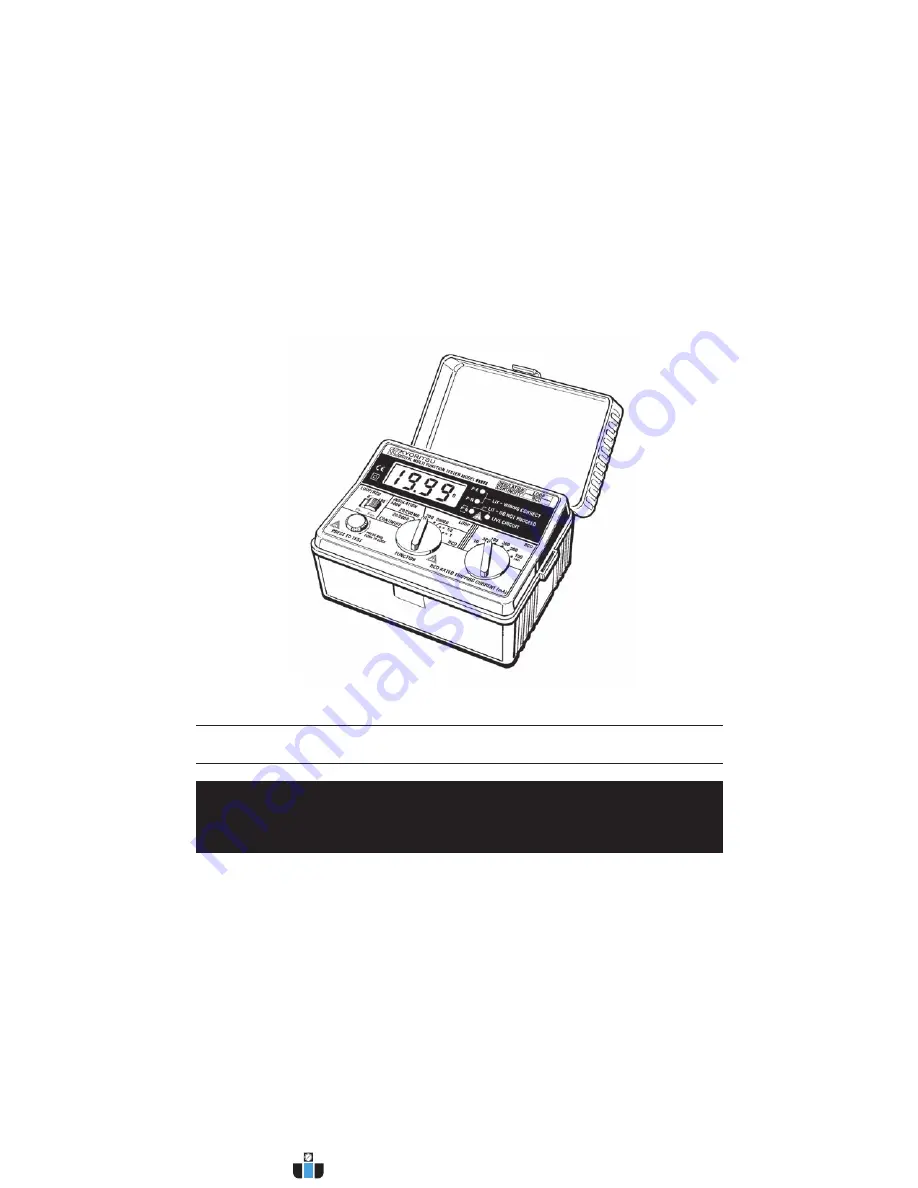
MODEL 6010A

MULTI-FUNCTION  TESTER

INSTRUCTION  MANUAL

KYORITSU  ELECTRICAL  INSTRUMENTS  WORKS,LTD.

www.calcert.com

sales@calcert.com

1.800.544.2843

0

5

10

15

20

25

30

Summary of Contents for 6010A

Page 1: ...MODEL 6010A MULTI FUNCTION TESTER INSTRUCTION MANUAL KYORITSU ELECTRICAL INSTRUMENTS WORKS LTD www calcert com sales calcert com 1 800 544 2843 0 5 10 15 20 25 30 ...

Page 2: ...lation resistance measurement 14 6 Loop Impedance Tests 17 6 1 Voltage measurement 17 6 2 What is earth fault loop impedance 17 6 3 Automatic over temperature cut out 17 6 4 The loop impedance test 18 6 5 Loop impedance at 3 phase equipment 19 7 RCD Tests 21 7 1 Purpose of RCD Test 21 7 2 What does the RCD test really do 21 7 3 RCD testing 21 7 4 Testing RCDs used to provide supplementary protecti...

Page 3: ...ment is intended only for single phase operation at 230V AC 10 phase to earth or phase to neutral operation and then only for loop and RCD testing For use in the continuity testing and insulation testing modes this instrument must be used ONLY on circuits which are de energised 4 When conducting tests do not touch any exposed metalwork associated with the installation Such metalwork may become liv...

Page 4: ...instrument is a safety device The instrument should not be used if it is damaged or impaired in any way but returned to your distributor for attention 13 Do not operate the function selector whilst the instrument is connected to a circuit If for example the instrument has just completed a continuity test and an insulation test is to follow disconnect the test leads from the circuit before moving t...

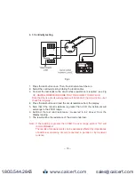
Page 5: ...RATED TRIPPING CURRENT SWITCH LIVE CIRCUIT LED CONNECTOR WIRING CHECK LED LCD DISPLAY Test Lead with IEC Connector LCD DISPLAY Test Lead for Continuity and Insulation Testing Fig 1 www calcert com sales calcert com 1 800 544 2843 0 5 10 15 20 25 30 ...

Page 6: ...mode the instrument provides a short circuit current of 200mA as required in IEC 61557 4 EN 61557 4 1997 Continuity and insulation resistance functions have the following features Live circuit warning A colour coded LED warns if the circuit under test is live Auto discharge Electric charges stored in capacitive circuits are discharged automatically after testing by releasing the test button Test c...

Page 7: ...nt tripping of some polarised RCDs when loop testing and may give a more accurate reading when testing RCDs Auto data hold Holds the displayed reading for a time after the test is complete Auto power off Automatically switches the instrument off after a period of approximately 1 minutes V NE Monitoring Circuit Automatically aborts measurement when the N E voltage rises to 50V or greater on RCD ran...

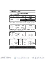
Page 8: ...61557 3 Rated Voltage AC Nominal Test Current at 0Ω External Loop Range Accuracy 230V 10 15 50Hz 25A 10ms 20Ω 3 rdg 8dgt 15mA 350ms max 2000Ω 3 rdg 8dgt Operating range as in IEC61557 20Ω Range 2Ω 19 99Ω 2000Ω Range 100Ω 1999Ω RCD testing to IEC61557 6 Function Rated Voltage AC Trip Current Settings Trip Current Duration Accuracy RCD 1 2 230V 10 15 50Hz 10 30 100 300 500mA 2000ms Trip Current 8 2 ...

Page 9: ...0 times for use by insulation resistance range Operating temperature 0 to 40 relative humidity 80 or less no and humidity condensation Storage temperature 10 to 50 relative humidity 75 or less no and humidity condensation Illuminates if there is an alternating voltage of 20V AC or more in the circuit under test before continuity or insulation resistance tests When DC voltage is detected across the...

Page 10: ... 600 V AC for 10 seconds Mains Voltage Indication On connecting test leads to the circuit under test on Loop and RCD ranges the LCD reads V PE Sign V PE Lo or V PE Hi is also shown when the voltage is 100V or less or 260V or greater respectively Equipment protected throughout by DOUBLE INSULATION or REINFORCED INSULATION Caution risk of electric shock Caution refer to accompanying instruction manu...

Page 11: ... alone and this should not include the resistance of any test leads used The procedure is to measure the resistance of the test leads and to subtract this from the instrument reading which includes the lead resistance Proceed as follows 1 Press the test button once Then the instrument switches on 2 Connect the ends of the test leads in use firmly together see Fig 2 and operate the test button 3 Th...

Page 12: ... read the circuit resistance from the display 5 Note that if the circuit resistance is greater than 20 Ω the instrument will autorange to the 200 Ω range 6 Subtract the test lead resistance measured in 4 2 above from the display reading 7 The result will be the resistance of the circuit under test Note If the reading is greater than 200Ω the over range symbol OL will remain displayed The results o...

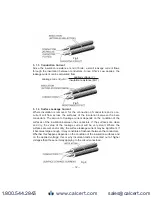
Page 13: ... made up of three components which are 1 capacitive current 2 conduction current and 3 surface leakage current 5 1 2 Capacitive Current The insulation between conductors which have a potential difference between them behaves as the dielectric of a capacitor the conductors acting as the capacitor plates When a direct voltage is applied to the conductors a charging current will flow to the system wh...

Page 14: ...onductors The amount of leakage current depends on the condition of the surfaces of the insulation between the conductors If the surfaces are clean and dry the value of the leakage current will be very small Where the surfaces are wet and or dirty the surface leakage current may be significant If it becomes large enough it may constitute a flashover between the conductors Whether this happens depe...

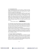
Page 15: ... reading indicates that the capacitance of the system is fully charged The system is charged to the full test voltage and will be dangerous if left with this charge Model 6010A provides an automatic path for discharging current as soon as the test button is released to ensure that the circuit under test is safely discharged If the wiring system is wet and or dirty the surface leakage component of ...

Page 16: ...horting out the lead ends A high reading will indicate that there is a faulty lead or that the fuse is blown 4 MAKE SURE THAT THE CIRCUIT TO BE TESTED IS NOT LIVE A warning lamp is lit if the instrument is connected to a live circuit but test the circuit as well 5 4 Insulation resistance measurement Model 6010A has a single test voltage of 500V DC 1 Press the test button once Then the instrument s...

Page 17: ...t dead before proceeding Fig 8 5 Press the test button when the display will show the insulation resistance of the circuit or the appliance to which the instrument is connected 6 Note that if the circuit resistance is greater than 20MΩthe instrument will automatically range to the 200MΩreading www calcert com sales calcert com 1 800 544 2843 0 5 10 15 20 25 30 ...

Page 18: ...circuit In the discharging process an LED illuminates and the live circuit warning buzzer will sound CAUTION NEVER TURN THE FUNCTION DIAL WHILST THE TEST BUTTON IS DEPRESSED AS THIS MAY DAMAGE THE INSTRUMENT NEVER TOUCH THE CIRCUIT TEST LEAD TIPS OR THE APPLIANCE UNDER TEST DURING INSULATION TESTING Note If the reading measured greater than 200MΩ the over range reading OL will be displayed www cal...

Page 19: ...ance The path followed by fault current as a result of a low impedance fault occurring between the phase conductor and earth is called earth fault loop Fault current is driven round the loop by the supply voltage the amount of current depending on the voltage of the supply and on the impedance of the loop The higher the impedance the lower will be the fault current and the longer it will take for ...

Page 20: ...ld these two lamps not be lit investigate the wiring connections of the installation and rectify any faults before proceeding with the test If the LED is lit do not proceed 1 Press the test button once Then the instrument switches on 2 Set the instrument to loop test 20Ωrange 3 If testing sockets connect the plug lead to the Model 6010A and push the moulded plug into the socket to be tested see Fi...

Page 21: ...crocodile clip to earth etc WARNING NEVER CONNECT THE INSTRUMENT TO TWO PHASES AT THE SAME TIME Testing as described in 6 4 and 6 5 above will measure the Phase Earth loop impedance If you wish to measure the Phase Neutral loop impedance then the same procedure should be followed except the earth clip should be connected to the neutral of the system i e the same point as the black neutral probe If...

Page 22: ... 20 BLACK NEUTRAL RED PHASE GREEN EARTH Fig 9 Fig 10 www calcert com sales calcert com 1 800 544 2843 0 5 10 15 20 25 30 ...

Page 23: ... lapse between the application of the current and the operation of the RCD 7 3 RCD testing 1 Press the test button once Then the instrument switches on 2 Set the RCD rated tripping switch to the trip rating of the RCD under test 3 Set the function switch to X1 2 for the no trip test which ensures that the RCD is operating within its specification and is not too sensitive 4 Set the LOOP RCD switch ...

Page 24: ...2 Set the LOOP RCD switch to 0 3 Connect the test instrument to the RCD to be tested 4 Make sure that the P E and P N wiring check lamps are lit If they are not disconnect the tester and check the wiring for a possible fault 5 If the lamps are lit press the test button to apply a test current of 150mA where the RCD should trip within 40ms the tripping time being shown on the display 6 Repeat the t...

Page 25: ...either case testing cannot be carried out as the test button does not function even if you press it When making a test with the range larger than the RCD rated tripping current it can happen that RCD trips and no is shown on the display The test button can be locked down for ease of use by pressing it and turning clockwise Do not forget to release test button by turning it anti clockwise before di...

Page 26: ... less than 1Ω resistance situated in the battery compartment together with a spare If the instrument fails to operate in the continuity test mode first disconnect the test leads from the instrument Next remove the battery cover take out the fuse and test its continuity with another continuity tester If it has failed replace it with a spare before refitting the battery cover Do not forget to obtain...

Page 27: ...tinuity and signs of damage 2 The continuity mode fuse situated in the battery compartment has been checked 3 The batteries are in good condition Please remember to give all the information possible concerning the nature of the fault as this will mean that the instrument will be serviced and returned to you more quickly 11 SERVICING www calcert com sales calcert com 1 800 544 2843 0 5 10 15 20 25 ...

Page 28: ...testing Fig 12 Pass the strap DOWN through the first case lug under the case and UP through the other lug Side the sholder pad onto the strap Feed the strap DOWN through the slots in the back of the test lead pouch Pass the strap through the buckle adjust the strap for length and secure www calcert com sales calcert com 1 800 544 2843 0 5 10 15 20 25 30 ...

Reviews: