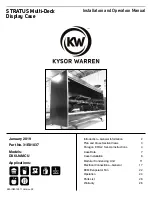


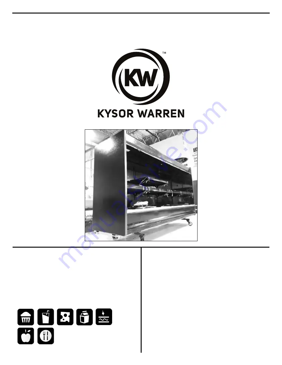
STRATUS Multi-Deck
Display Case
Installation and Operation Manual
KW-IOM-1037 | Version 02
January 2019
Part No. 31E01037
Models:
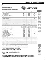
DX6LN-MCU
Applications:
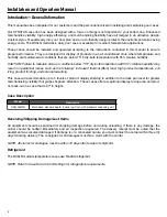
Introduction—General Information
2
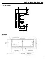
Plan and Cross Section Views
3
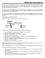
Paragon ERC-2 Set-Up Instructions
4
Case Data
7
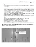
Case Installation
8
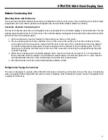
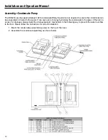
Modular Condensing Unit
11
Electrical Connections—General
17
ECM Evaporator Fan
22
Operation
24
Parts List
26
Warranty
26