background image

X8

rigging manual 1.0 (EN)

Summary of Contents for X8

Page 1: ...X8 rigging manual 1 0 EN...

Page 2: ...ual EN version 1 0 Distribution date September 24 2015 2015 L ACOUSTICS All rights reserved No part of this publication may be reproduced or transmitted in any form or by any means without the express...

Page 3: ...ocket 16 EMBi 17 Subwoofer 17 Rigging procedures 18 Mounting on a U bracket 18 Using a U bracket with X UTILT 23 Flying with a U bracket 29 Flying with X BAR 36 Pole mounting with a U bracket 42 Forbi...

Page 4: ...4 EMBi specifications 56...

Page 5: ...s the use of safety slings at all times Be cautious when ground stacking a loudspeaker array Do not stack the loudspeaker array on unstable ground or surface If the array is stacked on a structure pla...

Page 6: ...L Acoustics X8 As part of a continuous evolution of techniques and standards reserves the right to change the specifications of its products and the content of its document without prior notice Pleas...

Page 7: ...for 250 kg X UTILT U bracket wallmount for X series with tilt adjustment X BAR Rigging bar for X series X UL8 Long U bracket for X8 X US8 Short U bracket for X8 Software applications Soundvision 3D a...

Page 8: ...h the safety factor is always compliant with the 2006 42 EC Machinery Directive regardless of the other deployment parameters site angles inter enclosure angles etc The maximum limit gives the maximum...

Page 9: ...Soundvision The overall safety factor of a specific mechanical configuration always corresponds to the lowest safety factor among all the linking points Always model the system configuration with the...

Page 10: ...n 1 0 10 Rigging system description X8 X8 features a M8 DIN580 threaded insert designed to implement a secondary safety The logo on the enclosure front can be rotated to adapt to every configuration X...

Page 11: ...UL8 X8 can be fitted with a short U bracket X US8 or a long U bracket X UL8 The brackets are secured in the enclosure inserts with two threaded knobs A spring lock safety mechanism secures the knobs...

Page 12: ...ion 1 0 12 X US8 and X UL8 can be used for wall mounting ceiling mounting or flying X8 With the short U bracket in horizontal position the enclosure applies a diagonal force of 179 dekanewtons on the...

Page 13: ...ion 1 0 X US8 features an additional hole on the sides to closely fit the enclosure and to optimize visual impact When using the additional hole consider the maximum site angle available See Maximum a...

Page 14: ...negative site angle setting combined with azimuth angle setting capabilities in a wall mount configuration The site angle can be set from 0 to 45 in 5 steps The azimuth angle can be adjusted with the...

Page 15: ...Rigging system description 15 X8 rigging manual EN version 1 0 X BAR shall be secured to the inserts on the enclosure perpendicular to the front Five angulation holes are available 5 4 3 2 1...

Page 16: ...scription X8 rigging manual EN version 1 0 16 X BAR is compatible with a CMU 1 T 12 mm shackle provided and with CLAMP250 Elements for pole mounting Pole socket X8 features a 35 mm pole socket integra...

Page 17: ...g system description 17 X8 rigging manual EN version 1 0 EMBi EMBi is a pole mount adapter for X US8 35 mm pole The site angle can be adjusted with the U bracket Subwoofer SB15m features a 35 mm pole...

Page 18: ...fety for flown arrays When flying an array use the M8 DIN580 threaded insert to implement a secondary safety Ceiling mounting Additional holes on the short U bracket can be used for optimal visual imp...

Page 19: ...appropriate safety factor Procedure 1 Drive the knobs in the inserts on the enclosure Stop when the threading is halfway in 2 Secure the U bracket to the wall using M10 screws When securing the U brac...

Page 20: ...ing procedures X8 rigging manual EN version 1 0 20 4 Push until the knobs are locked inside the spring lock safety mechanism SHLAK 5 Set the site angle Use the screw as a reference point to read the l...

Page 21: ...Rigging procedures 21 X8 rigging manual EN version 1 0 6 Tighten the knobs Make sure the enclosure is steady...

Page 22: ...Disassembly Procedure 1 Loosen the knobs until the enclosure can rotate freely Do not unscrew the knobs all the way 2 On both sides pull on the safety mechanism while lifting the enclosure by the kno...

Page 23: ...X US8 or X UL8 rigging accessories X UTILT 2 x M10 screws additional material electric screwdriver min number of operators 1 Additionnal safety for flown arrays When flying an array use the M8 DIN580...

Page 24: ...g manual EN version 1 0 24 Assembly Procedure X UTILT can only be used vertically 1 Secure X UTILT to the wall using M10 screws 2 Secure the U bracket to X UTILT When using X US8 the bracket must be s...

Page 25: ...1 0 3 Secure the rigging arm to the U bracket Make sure the rigging arm is in the right position Always use the central insert 4 Choose the site angle and secure the rigging arm to X UTILT Refer to t...

Page 26: ...e enclosure Stop when the threading is halfway in 6 Lift the enclosure by the knobs and place it inside the U bracket Adjust the knobs on both sides so that the safety washer is between the hook and t...

Page 27: ...Rigging procedures 27 X8 rigging manual EN version 1 0 8 Set the azimuth angle Use the screw as a reference point to read the label 9 Tighten the knobs Make sure the enclosure is steady...

Page 28: ...sassembly Procedure 1 Loosen the knobs until the enclosure can rotate freely Do not unscrew the knobs all the way 2 On both sides pull on the safety mechanism while sliding the enclosure out of the U...

Page 29: ...t flying rigging accessories X US8 or X UL8 additional material truss clamp min number of operators 1 Additionnal safety for flown arrays When flying an array use the M8 DIN580 threaded insert to impl...

Page 30: ...0 30 Assembly Procedure 1 Drive the knobs in the inserts on the enclosure Stop when the threading is halfway in 2 Place the U bracket around the assembly Adjust the knobs on both sides so that the sa...

Page 31: ...manual EN version 1 0 3 Push down until the knobs are locked inside the spring lock mechanism SHLAK Alternatively use the additional hole on the U bracket The hooks on the bracket must be oriented to...

Page 32: ...Rigging procedures X8 rigging manual EN version 1 0 32 Make sure the flat washer goes through the hole on the bracket 4 Tighten the knobs and fly the enclosure with a clamp...

Page 33: ...igging procedures 33 X8 rigging manual EN version 1 0 5 Loosen the knobs to set the site angle Use the screw as a reference point to read the label 6 Tighten the knobs Make sure the enclosure is stead...

Page 34: ...Rigging procedures X8 rigging manual EN version 1 0 34 Maximum angles When using the additional hole on the U bracket consider the maximum negative site angle available 28...

Page 35: ...ng procedures 35 X8 rigging manual EN version 1 0 Disassembly Procedure 1 Place the enclosure on a flat surface 2 Loosen the knobs 3 Pull on the safety mechanism and remove the U bracket from the encl...

Page 36: ...X BAR type of deployment flying rigging accessories X BAR CMU 1 T 12 mm shackle additional material CLAMP250 optional min number of operators 1 Additionnal safety for flown arrays When flying an array...

Page 37: ...37 X8 rigging manual EN version 1 0 Assembly Procedure 1 Lay the enclosure on a flat surface 2 Drive the X BAR in the insert 3 Rotate the X BAR until perpendicular to the front grill Use the screws a...

Page 38: ...ging manual EN version 1 0 38 4 Tighten the X BAR a Lift the lever and rotate it counter clockwise b Release the lever and rotate it clockwise c Repeat until the X BAR is tightly secured d Finally sto...

Page 39: ...tion the shackle or CLAMP250 to select the site angle Rear extension on horizontal enclosure 28 16 3 11 24 Front extension on horizontal enclosure 1 14 27 37 47 Rear extension on vertical enclosure 5...

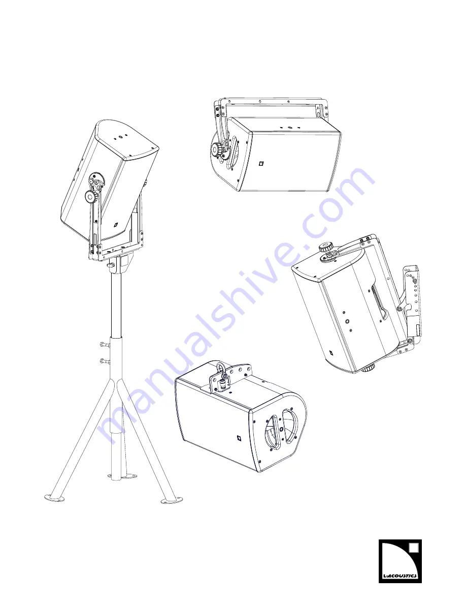
Page 40: ...Rigging procedures X8 rigging manual EN version 1 0 40 6 Lift the assembly...

Page 41: ...s 41 X8 rigging manual EN version 1 0 Disassembly Procedure 1 Take down the assembly 2 Lift the lever and rotate it clockwise 3 Release the lever and rotate it counter clockwise 4 Repeat until the X B...

Page 42: ...ging procedures X8 rigging manual EN version 1 0 42 Pole mounting with a U bracket type of deployment pole mounting X US8 rigging accessories EMBi additional material 35 mm pole min number of operator...

Page 43: ...N version 1 0 Assembly Procedure 1 Secure EMBi to the U bracket with the provided bolts and nuts 2 Secure the U bracket to the enclosure using the additional holes The hooks on the bracket must be ori...

Page 44: ...Rigging procedures X8 rigging manual EN version 1 0 44 Make sure the flat washer goes through the hole on the bracket 3 Tighten the knobs reverse the assembly and mount it on a pole 4 Tighten EMBi...

Page 45: ...g manual EN version 1 0 5 Loosen the knobs to set the site angle Consider the maximum positive site angle available 28 6 Tighten the knobs Make sure the enclosure is steady The assembly can be mounted...

Page 46: ...al EN version 1 0 46 Disassembly About this task Remove the assembly from the pole before disassembling the enclosure and the bracket Procedure 1 Loosen EMBi to remove the assembly from the pole 2 Rem...

Page 47: ...Forbidden configurations 47 X8 rigging manual EN version 1 0 Forbidden configurations Forbidden Authorized...

Page 48: ...rigging manual EN version 1 0 48 Illustrations Loudspeaker enclosures X8 passive 2 way coaxial enclosure SB15m high power compact subwoofer Rigging elements CLAMP250 Clamp certified for 250 kg EMBi P...

Page 49: ...rsion 1 0 X UTILT U bracket wallmount for X series with tilt adjustment X BAR Rigging bar for X series X UL8 Long U bracket for X8 X US8 Short U bracket for X8 Software applications Soundvision 3D aco...

Page 50: ...nar vents 1 1 5 compression driver neodymium weather resistant partial horn Nominal impedance LF 8 HF 8 Connectors IN SpeakON LINK SpeakON Rigging and handling 1 handles DIN580 compatible M8 threaded...

Page 51: ...ing manual EN version 1 0 X8 dimensions On end H W D 424 mm 250 mm 264 mm 16 7 in 9 8 in 10 4 in Monitor H W D 278 mm 424 mm 306 mm 10 9 in 16 7 in 12 in 264 mm 10 4 in 250 mm 9 8 in 424 mm 16 7 in 30...

Page 52: ...1 0 52 X UL8 specifications Description Long U bracket for X8 Weight net 2 3 kg 5 lb Material High grade steel with anti corrosion coating X UL8 dimensions 53 mm 2 1 in 80 mm 3 1 in M10 487 mm 19 2 in...

Page 53: ...n 1 0 X US8 specifications Description Short U bracket for X8 Weight net 2 3 kg 5 lb Material High grade steel with anti corrosion coating X US8 dimensions M10 53 mm 2 1 in 80 mm 3 1 in 355 mm 14 in 3...

Page 54: ...ual EN version 1 0 54 X BAR specifications Description Rigging bar for X series Weight net 1 1 kg 2 4 lb Material High grade steel with anti corrosion coating X BAR dimensions 185 mm 7 3 in 13 mm 0 5...

Page 55: ...ILT specifications Description U bracket wallmount for X series with tilt adjustment Weight net 1 5 kg 3 3 lb Material High grade steel with anti corrosion coating X UTILT dimensions 300 mm 11 8 in M1...

Page 56: ...g manual EN version 1 0 56 EMBi specifications Description Pole mount socket Weight net 0 5 kg 1 1 lb Material High grade steel with anti corrosion coating EMBi dimensions 46 mm 1 8 in 35 mm 1 4 in 76...

Page 57: ......

Reviews: