


i
This manual is subject to change without notice. You may obtain the newest version of the manual at www.lamarchemfg.com
106 Bradrock Dr. Des Plaines, IL 60018-1967
CPN 40966
Instruction Drawing Number: P25-LA31STD-1
Tel: 847 299 1188
Fax: 847 299 3061
Revision A08
Rev. Date: 01/21
ECN: 22782
Installation and Operation Manual
La Marche Manufacturing Company
www.lamarchemfg.com
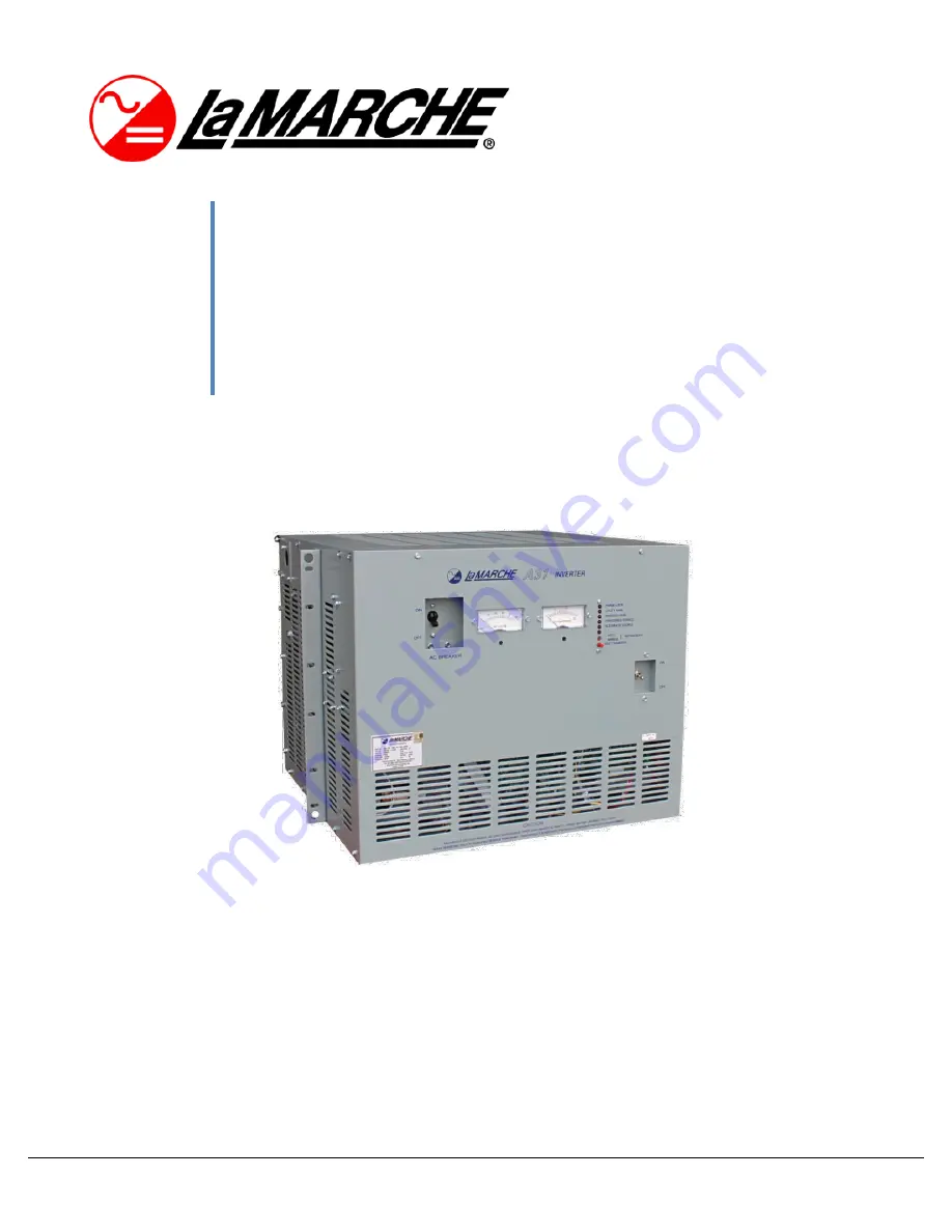
A31
DC
–
AC Sine Wave Inverter


