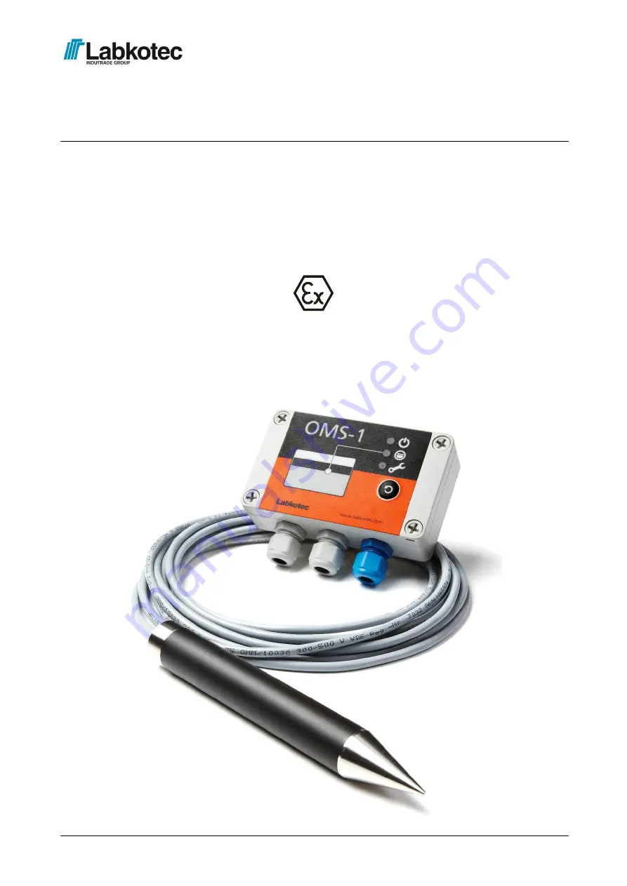
background image

Labkotec Oy 
Myllyhaantie 6 
FI-33960 PIRKKALA 
FINLAND  
Tel:  +358 29 006 260 
Fax:  +358 29 006 1260 


      8.8.2019 

Internet: www.labkotec.com 


D15530_E-5


1/13


Copyright © 2019 Labkotec Oy 


                              We reserve the right for changes without notice 


OMS-1 


Oil Separator Alarm Device 


Installation and Operating Instructions 


Summary of Contents for OMS-1

Page 1: ...FINLAND Tel 358 29 006 260 Fax 358 29 006 1260 8 8 2019 Internet www labkotec com D15530_E 5 1 13 Copyright 2019 Labkotec Oy We reserve the right for changes without notice OMS 1 Oil Separator Alarm D...

Page 2: ...it 4 2 2 OMS sensor 5 2 3 Cable joint 5 3 OPERATION 6 3 1 Modes of operation 6 4 TROUBLE SHOOTING 8 5 REPAIR AND SERVICE 9 6 SAFETY INSTRUCTIONS 9 7 TECHNICAL DATA 10 APPENDIX 1 OMS SYSTEM DRAWING 11...

Page 3: ...led into the light liquid storage chamber and gives an alarm when the chamber oil layer reaches a pre determined level The sensor is normally immersed in water The function is based on the measurement...

Page 4: ...located in the base plate of the enclosure beneath the mounting holes of the front cover The connectors of the external conductors are isolated by separating plate The plate must not be removed The co...

Page 5: ...elded cable is used cable shields and possible excess wires need to be connected to the same point in galvanic contact Please make sure that the sensor and cable between OMS 1 control unit and the sen...

Page 6: ...cabling If necessary contact a representative of the manufacturer 3 1 Modes of operation Normal mode no alarms Sensor is totally immersed in water Mains LED indicator is on Other LED indicators are of...

Page 7: ...button Oil Alarm and Fault LED indicators are immediately on Buzzer is immediately on Relay de energize after 2 sec of continuous pressing When the Reset Test push button is released LED indicators a...

Page 8: ...son Resistance in sensor circuit too high cable break or out of connector or too low cable in short circuit The sensor might also be broken To do 1 Make sure that the sensor cable has been connected c...

Page 9: ...osive atmospheres the national requirements and relevant standards as IEC EN 60079 25 and or IEC EN 60079 14 must be taken into account Warning If the cabling is voltage tested the sensor must be disc...

Page 10: ...3 mW Manufacturing year Please see the serial number on the type plate xxx x xxxxx xx YY x where YY manufacturing year e g 19 2019 In the cable parameters of OMS 1 sensor connection must be taken into...

Page 11: ...APPENDIX 1 OMS System drawing...

Page 12: ...APPENDIX 2 EU DECLARATION OF CONFORMITY...

Page 13: ...APPENDIX 3 EU DECLARATION OF CONFORMITY...

Reviews: