background image


BANDSAW OWNER'S MANUAL


Part No. 


MBAND18BX2203


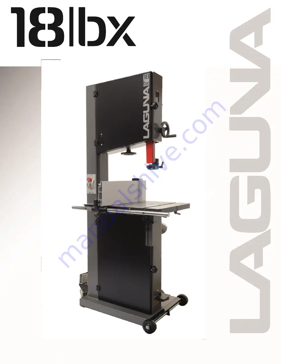
LT18BX Bandsaw 220V 3HP 16" Resaw


Revision 3, 2/10/2022


© 2022, Laguna Tools, Inc. LAGUNA® and the LAGUNA Logo® 


are the registered trademarks of Laguna Tools, Inc. All rights reserved.


Summary of Contents for MBAND18BX2203

Page 1: ...WNER S MANUAL Part No MBAND18BX2203 LT18BX Bandsaw 220V 3HP 16 Resaw Revision 3 2 10 2022 2022 Laguna Tools Inc LAGUNA and the LAGUNA Logo are the registered trademarks of Laguna Tools Inc All rights...

Page 2: ...ication sheet 10 Noise emission 11 Receiving your machine 11 Introduction to Bandsaws 12 What you will receive with your Bandsaw 13 Parts of the Bandsaw 15 Where to locate your machine 19 Unpacking yo...

Page 3: ...3 Laguna Tools MBAND18BX2203 Bandsaw User Manual Safety Rules...

Page 4: ...4...

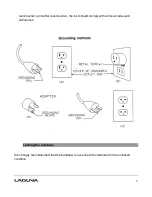
Page 5: ...ce that is green with or without yellow stripes is the equipment grounding conductor If repair or replacement of the electric cord or plug is necessary do not connect the equipment grounding conductor...

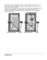
Page 6: ...nection and after reconnection the tool should comply with all local codes and ordinances Locking the bandsaw It is strongly recommended that the bandsaw is never be left unattended in the unlocked co...

Page 7: ...ade from wood or plastic First push down the emergency stop Then lock the cover together by putting padlocks not included on the two handles on the control panel To safeguard your machine from unautho...

Page 8: ...e caused where repair or alterations have been made or attempted by others Laguna Tools Inc is not responsible for additional tools or modifications sold or performed other than from by Laguna Tools I...

Page 9: ...apacity 16 406 4mm Minimum blade length 143 3 4 3 651mm Maximum blade length 145 1 2 3 695mm Maximum blade width 1 1 4 31 75mm Minimum blade width 1 8 3mm Guides Laguna ceramic Height 77 3 4 1 975mm M...

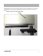
Page 10: ...10 Industrial work light Optional Fence Face Dimensions 7 1 4 x 2 2 3 4...

Page 11: ...of ambient noise It is also possible that legal noise exposure limits will vary from country to country Receiving your machine It is probable that a third party will deliver your machine Before you u...

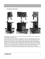
Page 12: ...ch creates the continuous sawing action Because the direction of the blade is always downward toward the table there is little danger except for special cuts that the wood will be thrown back at the o...

Page 13: ...e is thin it can cut thick stock with a minimum of horsepower For this reason the bandsaw is often used when valuable pieces of wood are made into a thin piece of veneer What you will receive with you...

Page 14: ...14 Fence parts Fence guide bar Fence stop...

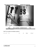
Page 15: ...15 Parts of the Bandsaw Note The mobility kit and light are optional 4 2 1 9 5 8 16 6 12 13 Table ratchet handles washers Rubber feet and fixings Table Fence guide bar attachment parts T bar...

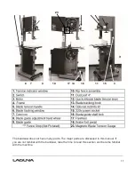
Page 16: ...7 14 18 11 15 3 The bandsaw does not have many parts The major parts are discussed in this manual If you are not familiar with the bandsaw take the time to read this section and become familiar with t...

Page 17: ...very rigid as it takes the strain of the blade being tensioned 5 Blade tension handle The blade tension handle moves the blade tension and tilt assembly vertically The vertical action compresses a sp...

Page 18: ...and is lockable in any position to suit the width of cut The fence attachment casting is attached to the cast knuckle with three screws that when loosened allow the fence to be adjusted for drift The...

Page 19: ...f the bandsaw The bandsaw is provided with a 220V socket that the light can be connected to 16 Blade guide shaft lock knob The upper blade guide is fixed to the blade guide Rubber feet shaft which is...

Page 20: ...justs the axis of the wheel so that it runs true with the lower wheel The second function is to tension the blade which is achieved by adjusting the upper flywheel vertically A handle is located below...

Page 21: ...ck your machine you will need tin snips a knife and a wrench Note The machine is heavy and if you have any doubt about the described procedure seek professional assistance Do not attempt any procedure...

Page 22: ...the rubber feet Method 1 Fit the rubber feet to the bandsaw prior to removing it from the packaging Method 2 1 Support the bandsaw on wooden blocks 2 Assemble the rubber feet with the fixings provide...

Page 23: ...ve the two rubber feet that are close to the front wheels Note Never operate the bandsaw with the mobility kit engaged or the front wheel assembly locking screw not engaged Fitting the table Trunnion...

Page 24: ...d to quickly align the table after tilting The stop bolt hits the tilt blanking disc when it is positioned over the table tilt hole When the tilt blanking disc is moved away from the hole it allows th...

Page 25: ...be detailed later in the manual Fitting the table rule Table rule with fixings Table with rule mounted Attach the rule to the table with the fixings supplied Do not fully tighten the bolts as the pos...

Page 26: ...the back of the bandsaw closest to the column 2 Slide the fence support onto the fence bar and fit the fence support clamp screw 3 Slide the fence onto the clamping strip 4 Lift the fence just clear o...

Page 27: ...table insert that is held in position with a screw The table insert is removed when blades are removed or fitted to the machine The insert is made of soft aluminum so that if the blade wanders and con...

Page 28: ...T slot on top of the fence when it is on the vertical position The 0 on the scale should be adjusted and set to be align up to the front tip of the blade Then refer to the scale slide the fence stopp...

Page 29: ...29 Fitting the optional light Fixing screws and cable clips Light fitted in position Suggested cable route Light plugged into socket...

Page 30: ...g and Cable The bandsaw is supplied pre wired with a 220V 3 pin plug It is Emergency stop button recommended that the bandsaw be connected to a 15 amp breaker The start stop switch activates the motor...

Page 31: ...hield and hearing protection 5 Wear a dust mask long term exposure to the fine dust created by the bandsaw is not healthy 6 Remove your tie rings watch and all jewelry Roll up your sleeves you do not...

Page 32: ...ble split clamp screw Blade in table split Plastic blanking block and back guide out as far as they will go both upper and lower guides This will ensure that they do not interfere with the blade while...

Page 33: ...ecommends that all blades regardless of their size should run in the center of the wheel The advantage of running the large blades with the teeth not contacting the rubber of the wheel is that they ca...

Page 34: ...be viewed This will Blade tension wheel assist you while you are tracking the blade Tensioning the blade There are a lot of opinions on how to tension a blade and if you should buy a blade tension gau...

Page 35: ...Blade tension indicator Close all the doors and ensure that all the guards are fitted Start the band saw and look at the blade from the front of the machine Start to detention the blade very slowly un...

Page 36: ...he table slot Adjusting the blade guides Introduction Welcome to a new era in band sawing You have purchased a bandsaw with a revolutionary blade guide system that is designed to give you years of saf...

Page 37: ...atly extend the life of your guide 5 The Laguna guide system can be used with 1 8 to 1 1 4 blades 6 The Laguna guide system uses ceramic to support and guide the blade This has many advantages very po...

Page 38: ...t clearance until you gain experience Tighten the clamp screws and remove the paper Rotate the blade by hand ensuring that the weld of the blade does not hit the ceramic blocks as this will cause dama...

Page 39: ...e or return it to your supplier Loosen the rear guide clamp screw and push the guide forward so that it just touches the back of the blade Tighten the guide in position Rotate the blade by hand and ch...

Page 40: ...frequently used techniques for making straight bandsaw cuts One technique is to use a single point to guide the work The rationale for using a single point is that the saw may tend to cut at a slight...

Page 41: ...skilled at the procedure Once you have mastered the process it should only take a minute to perform the adjustment Note Each blade has a slightly different drift and each time you change a blade you...

Page 42: ...d where the fence in the high position would make it awkward to complete cuts The fence in the high position is used for supporting tall work Changing the fence height 1 Loosen the clamp screws that a...

Page 43: ...step in attaining good bandsaw performance The most frequently asked question is How do I decide on the correct blade to use The answer is not simple and we will explore it in this section of the man...

Page 44: ...erial the finer the pitch that is required For example exotic hardwoods such as ebony and rosewood require blades with a finer pitch than American hardwoods such as oak or maple Soft wood such as pine...

Page 45: ...aggressive the tooth the slower the cut and the harder must be the wood that the blade is suitable to cut Hook teeth have a progressive cutting angle and take the form of a progressive radius They ar...

Page 46: ...ramic will round the back of the blade as it is used However if you decide that you want to round the back of the blade a procedure follows A round blade back creates smooth interaction between the th...

Page 47: ...Certain woods will dull a steel blade very quickly especially tropical hardwoods teak koa etc Other woods with a high silicon content will also dull the blade quickly even a cut as short as 6 will cau...

Page 48: ...des can often save cutting and finish time The chart above is only a rough guide and is not to scale but from the information you can construct your own guide How to coil a bandsaw blade Without a dou...

Page 49: ...ng This method works the same as the method above but rather than holding the blade with both hands grasp the blade at the top while holding the bottom of the blade with your foot teeth still facing a...

Page 50: ...ns Simultaneously twist your left hand up and your right hand down As the blade starts to fold move your hands closer together while tilting your left hand to the right and your right hand to the left...

Page 51: ...51 Step 1 Step 2 Step 3 Step 4 Done Maintenance...

Page 52: ...They Tire brush wear in the middle which causes a concavity in the tire The deformation makes it hard to track the blades and for this reason it is important to maintain the original shape of the tire...

Page 53: ...drive belt and tighten the motor clamping bolts Note It is better to replace the drive belt early than to have a breakdown during an important job Note Take great care not to damage the bearings when...

Page 54: ...g screw D occurred Back guide forward back adjustment 1 Four clamping bolts and two Allen jacking screws are provided 2 Slightly loosen the two clamping bolts A and tighten the bottom Allen screw B wi...

Page 55: ...all adjustments as a small movement of the jack screws makes a large adjustment of the table Move the table back to 90 degrees clamp in position and check if the blade is square to the table with the...

Page 56: ...the lock nut on the tilt stop bolt and adjust in the required direction Square Clamp screws Adjusting screws 1 Using an engineer s square check that the fence is square to the table 2 If the fence is...

Page 57: ...ne open the doors and try to turn the wheel by hand If the wheel is not turning check the reason for the jamming Typical reasons are guides too tight wood jammed in the wheel Adjust guides or remove j...

Page 58: ...blade Change the blade 2 Crown on the wheels worn or damaged tire Dress the tires The blade kicks Bad blade Replace the blade The blade makes a clicking noise Bad weld Dress the weld or change the bla...

Page 59: ...59...

Page 60: ...60 LT18BX MBAND18BX2203 220V wiring diagram...

Page 61: ...1 PBAND18BX2203 2 Ball Bearing 6204LLU 2 PBAND18BX2203 4 PU Tire 1 PBAND18BX2203 5 Upper Wheel 1 PBAND18BX2203 6 Upper Wheel Shaft 1 PBAND18BX2203 7 Upper Wheel Shaft Bracket 1 PBAND1412 175 9 Socket...

Page 62: ...ND1412 175 24 Handle 1 PBAND1412 175 25 Door Hinge Set 2 PBAND1412 175 25 1 Door Hinge Left 2 PBAND1412 175 25 2 Door Hinge Right 2 PBAND1412 175 25 3 Socket Head Cap Screw M5x0 8x35 2 PBAND1412 175 2...

Page 63: ...1 PBAND1412 175 49 Adjusting Knob 1 PBAND1412 175 50 Tension Label 1 PBAND18BX2203 51 Upper Door 1 PBAND18BX2203 52 Logo Label 1 PBAND1412 175 53 Hinge Cover 1 MBAND14BX110 175 54 Emergency Stop 1 PBA...

Page 64: ...M4 2 MBAND14BX110 175 68 Screw M4x0 7x8 4 Part No Item Description Specification Qty Lower Wheel and Motor Assembly PBAND18BX2203 1 Hex Nut 5 8 18UNF LH 1 PBAND18BX2203 2 Ball Bearing 6204LLU 2 PBAND1...

Page 65: ...Screw M5x0 8x30 3 PBAND1412 175 2 17 Flat Washer M5 1 PBAND1412 175 2 18 Brush 2 PBAND1412 175 2 19 Hex Nut M5x0 8 64 PBAND1412 175 2 20 Insert Block 11 PBAND1412 175 2 21 Shelf 1 PBAND1412 175 2 22 H...

Page 66: ...5 2 42 Flat Washer 3 8 6 PBAND1412 175 2 43 Lock Washer 3 8 5 PBAND18BX2203 2 44 Hex Nut 3 4 16UNF 1 PBAND18BX2203 2 45 Motor 1 PBAND18BX2203 2 45 1 Motor Fan not shown 1 PBAND18BX2203 2 45 2 Motor Fa...

Page 67: ...ew M3 20mm 2 MBAND14BX110 175 2 62 Screw 1 4 20x3 8 2 MBAND14BX110 175 2 63 Brake Assembly 1 MBAND14BX110 175 2 63P Brake Pad not shown 2 pieces MBAND14BX110 175 2 64 Disc 1 MBAND14BX110 175 2 65 Inne...

Page 68: ...68...

Page 69: ...3 10 Set Screw M4x0 7x4 4 PBAND1412 175 3 11 Table Insert 1 PBAND18BX2203 3 12 Table 1 PBAND18BX2203 3 13 Scale 1 PBAND18BX2203 3 14 Scale Plate 1 PBAND1412 175 3 15 Hex Cap Screw M5x0 8x10 2 PBAND14...

Page 70: ...BAND1412 175 3 37 Phillips Flat Head Screw M4x0 7x8 1 PBAND1412 175 3 38 Hex Nut 5 16 18 1 PBAND1412 175 3 39 Flat Washer 5 16 1 PBAND1412 175 3 40 Lock Handle 1 PBAND18BX2203 3 41 Nylon Inserted Lock...

Page 71: ...71...

Page 72: ...D18BX2203 4 10 Magnet 1 PBAND1412 175 4 11 Guide Bar Bracket 1 PBAND1412 175 4 12 Socket Head Cap Screw 5 16 18x1 1 4 2 PBAND1412 175 4 13 C Ring S12 2 PBAND1412 175 4 14 Worm 1 PBAND1412 175 4 15 E R...

Page 73: ...PBAND1412 175 4 32 Guide Bracket 1 PBAND1412 175 4 33 Lock Handle 1 PBAND1412 175 4 34 Support Shaft 1 PBAND1412 175 4 35 Lock Knob 1 PBAND1412 175 4 36 Socket Head Button Screw 1 4 20x1 2 2 PBAND141...

Page 74: ......

Page 75: ...on Qty 230V Industrial Work Light Optional PBAND14BX220 250 7 1 14BX220 250 701 Work Light 230V 1 PBAND1412 175 7 2 1412 702 Screw M4x0 7x20 4 PBAND1412 175 7 3 1412 703 Flat Washer M4 4 PBAND1412 175...

Page 76: ......

Reviews: