background image

Summary of Contents for TWIN 13-E

Page 1: ......

Page 2: ......

Page 3: ...tallazione deve essere effettuata da personale qualificato che sar responsabile del rispetto delle norme di sicurezza vigenti ITALIANO ENGLISH Read carefully all warnings and instructions contained in...

Page 4: ...__________________19 SCHEMA MONTAGGIO DISPOSITIVI DI SICUREZZA_____________________20 Complimenti Per l ottima scelta La ringraziamo per la preferenza accordata ai ns prodotti LAMBORGHINI dal1959attiv...

Page 5: ...ply to the European Directive Conformit la Directive Europ enne In bereinstimmung mit den EG Richtlinien Conformidad con la Directiva Europea Voldoen aan de Europese Richtlijn 73 23 CEE 89 336 CEE 89...

Page 6: ...Non ostruire le griglie di aspirazione o di dissipazione In caso di guasto e o di cattivo funzionamento dell appaecchio disattivarlo astenendosi da qual siasi tentativo di riparazione o di intervento...

Page 7: ...o l installazione del bruciatore lo abbia fissato saldamente al generatore di calore in modo che la fiamma si generi all interno della camera di combustione del generatore stesso Prima di avviare il b...

Page 8: ...a di alcune regole fondamentali quali non toccare l apparecchio con parti del corpo bagnate o umide e o a piedi nudi non tirare i cavi elettrici non lasciare esposto l apparecchio ad agenti atmosferic...

Page 9: ...a che la linea di adduzione e la rampa gas siano conformi alle norme e prescrizioni vigenti b che tutte le connessioni gas siano a tenuta c che le aperture di areazione del locale caldaia siano dimens...

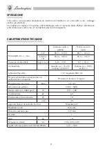
Page 10: ...bustibile kg h m3 n 6 8 13 8 8 1 16 4 Combuslibile Gasolio p c i 10 210 kcal kg 1 3 E 20 C Metano p c i 8570 kcal m3 n Tubazione flessibile 1 4 lunghezza 800 mm Pompa combustibile autoaspirante con el...

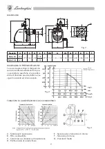
Page 11: ...te effettuando le pro ve secondo le specifiche e le caratteri stiche di focolare previste dalle norme vigenti nazionali ed internazionali Fig 3 TUBAZIONI DI ALIMENTAZIONE OLIO COMBUSTIBILE Fig 4 A Tub...

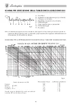
Page 12: ...su richiesta C Filtro gas su richiesta D Regolatore di pressione su richiesta E Pressostato gas F Presa pressione gas su pressostato G Elettrovalvola gas H Bruciatore DIAGRAMMA PER LA DETERMINAZIONE D...

Page 13: ...la fiamma durante il normale funzionamento avviene il blocco totale Il riavviamento del bruciatore Si effettua pre mendo il pulsante di ricarica blocco 17 La linea di alimentazione deve giungere trami...

Page 14: ...12 Fig 8...

Page 15: ...0 ruotando la vite A montata sul coperchietto Ruotando in senso orario si ottiene l avanzamento del disco di pressu rizzazione d una riduzione dell aria viceversa ruotando in senso antiorario si ottie...

Page 16: ...di comando siano collegate a terra L ugello 28 montato sul bruciatore sia di portata idonea alla caldaia Nel serbatoio ci sia olio combustibile e le saracinesche siano aperte Le serrande registro fum...

Page 17: ...le ll bruciatore si metter in funzione e dopo aver effettuato il ciclo di avviamento si former la fiamma che rester accesa fintanto che non interverr un apparecchio di comando Non appena il bruciatore...

Page 18: ...ia durante il funzionamento f intervenire il pressostato aria e manda il bruciatore in blocco Prima di ritentare l accensione verificare l efficenza del ventilatore o del pressostato Fig 14 Fig 15 PRE...

Page 19: ...are panni puliti ed asciutti Nel rimontarla verificare che sia ben agganciata UGELLO 28 Sfilare i cavi di alta tensione 32 dal lato trasformatore la Fotocellula UV 31 svitare le viti fissag gio coperc...

Page 20: ...LE Chiudere la saracinesca sull aspirazione smontare il coperchio della pompa estrarre la cartuccia a rete lavarla con benzina e rimontare il tutto accuratamen te FILTRO SULLA TUBAZIONE OLIO COMBUSTIB...

Page 21: ...o fare bene attenzione a non pizzicare la guarnizione OR e verificare che non vi siano perdite di gas N B Nel caso si volesse procedere ad una verifica e pulizia degli organi della testa di combustion...

Page 22: ...ne 24 Vite regolazione aria 25 Ghiera su regolazione aria 26 Vite di regolazione pressione pompa 27 Attacco manometro 28 Ugello 29 Canotto portaugello 30 Anello di pressurizzazione 31 Fotocellula UV 3...

Page 23: ...0 C GIUNTO ANTIVIBRANTE 11 C RUBINETTO DI INTERCETTAZIONE 14 A B C PRESA PRESSIONE GAS 15 A PRESSOSTATO DI MINIMA PRESSIONE ARIA CON PRESA DI PRESS A COMPONENTI FORNITI A CORREDO DEL BRUCIATORE B GRUP...

Page 24: ...in this manual as they give important safety instructions regarding installation use and maintenance Keep this manual for future reference In stallation must be carried out by qualified personnel who...

Page 25: ...arket assisted by LAMBORGHINI SERVICE who assure qualified service and maintenance of the machines INDEX PAGE DECLARATION OF CONFORMITY_ _____________________________________ 3 GENERAL WARNINGS_______...

Page 26: ...ff devices Do not obstruct the intake or dissipation grilles In the event of failure and or bad functioning of the burner deactivate it and do not attempt to repair or work on it yourself Only profess...

Page 27: ...d the burner has firmly fixed it to the heat generator so that the flame is generated inside the combustion chamber of the generator Before starting the burner and at least once a year have profession...

Page 28: ...rical energy implies observance of some fundamental rules such as Do not touch the machine with wet or moist parts of the body and or with bare feet Do not pull on the electric cables Do not leave the...

Page 29: ...that the feed line and the gas ramp are in conformity with the regulations and provisions in force b that all the gas connections are gas tight c that the vents in the boiler room are dimensioned so...

Page 30: ...13 8 8 1 16 4 Fuel Diesel oil PCI 10 210 kcal kg 1 3 E 20 C Natural gas PCI 8570 kcal m3 n Flexible hoses length 800 mm Self suction fuel pump with incorporated electrovalve calibration pressure 12 k...

Page 31: ...ce with the flue specifications and characteristics as set out in the national and international regula tions in force Gas Diesel oil FIG 3 FUEL OIL FEED PIPES Pipe development Pipe development Suctio...

Page 32: ...pressure switch F Gas outlet on pressure switch G Gas electrovalve H Burner Fig 5 Note The gas pipe must conform to the regulations in force and both the accessories and the gas pipe must have a diame...

Page 33: ...operation the burner locks completely The burner is turned on again by pressing the lock reset button 17 t3 30 sec pre ventilation and pre ignition t1 3 sec MAX safety time OPERATING CYCLE Fig 7 EV1 g...

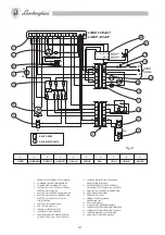
Page 34: ...11 MAIN SWITCH 12 REMOTE LIGHT FOR SEAL CONTROL DEVICE LOCK 13 REMOTE LIGHT FOR BURNER LOCK 14 VENT ELECTROVALVE CLOSURE CONTROL MICROSWITCH 15 CONNECTOR BLOCK TERMINAL 16 FAN MOTOR 17 AIR PRESSURE SW...

Page 35: ...can be moved forward or backward by turning the screw A fitted on the cover Turn clockwise to move the pressurization disc forward and decrease the air flow and anticlockwise to move the disc backward...

Page 36: ...d to earth the nozzle 28 fitted on the burner is of suitable capacity for the boiler there is fuel oil in the tank and that the gate valves are open the boiler flue gas registers and the stack are ope...

Page 37: ...et button 17 Close the main switch The burner starts and after running the starting cycle the flame is formed and burns until a con trol device intervenes As soon as the burner has started adjust the...

Page 38: ...g 14 Fig 15 To adjust the initial flow rate remove the protective cap turn it upside down and position it on the screw The flow rate is decreased by tightening and increased by loosening To adjust the...

Page 39: ...electrodes Unscrew the nozzle 28 from the holder taking care not to alter the position of the ignition electrodes 23 should this occur reposition everything according to the dimensions indicated in Fi...

Page 40: ...MBUSTION OIL PUMP Close the valve on the suction Remove the pump cover extract the filter cartridge clean with gasoline and ri assemble correctly COMBUSTION OIL PUMP Close the valve on the suction and...

Page 41: ...ed air When refitting the cover take care not to pinch the O ring and check that there are no gas leaks N B If you wish to check and clean the combustion head parts it is advisable to loosen the two l...

Page 42: ...or 23 Ignition electrodes 24 Air adjustment screw 25 Air adjustment ring nut 26 Pump pressure adjustment screw 27 Pressure gauge attachment 28 Nozzle 29 Nozzle holder 30 Pressurization ring 31 UV phot...

Page 43: ...N DAMPING JOINT 11 C SHUTOFF COCK 14 A B C GAS PRESSURE OUTLET 15 A MINIMUM AIR PRESSURE SWITCH WITH PRESSURE OUTLET A COMPONENTS PROVIDED WITH THE BURNER B PREASSEMBLED SAFETY AND VENT VALVE UNIT SUP...

Page 44: ......

Reviews: