

1
© Copyright 2020
Printed
Before You Start
General Information
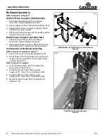
Your Third Function Valve Kit
is exclusively designed for
your Kubota tractors. Please read these installation
instructions thoroughly before assembling this kit to your
Kubota tractor and loader. Especially read information
relating to safety concerns.
These assembly instructions apply to the Third Function
Valve Kit Accessories listed below:
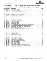
• 380-340A: 3FVK FF B2601. . . . . . . . . . . . . . . . page 8
• 380-149A: 3FVK PC B2601 . . . . . . . . . . . . . . . page 8
Further Assistance
Your Land Pride dealer wants you to be satisfied with your
new Third Function Valve Kit. If for any reason you do not
understand any part of this manual or are not satisfied
with the service received, the following actions are
suggested:
1. Discuss any problems you have with your Third
Function Valve Kit with your dealership service
personnel so they can address the problem.
2. If you are still not satisfied, seek out the owner or
general manager of the dealership, explain the
question/problem, and request assistance.
3. For further assistance write to:
Land Pride Service Department
1525 East North Street
P.O. Box 5060
Salina, Ks. 67402-5060
E-mail address
lpservicedept@landpride.com
When you see this symbol, the subsequent
instructions and warnings are serious - follow
without exception. Your life and the lives of
others depend on it!
!
WARNING: Cancer and reproductive harm.
!
California Proposition 65
IMPORTANT:
Before you begin, thoroughly read
these instructions and check to be sure all parts are
accounted for. Please retain these installation
instructions for future reference and parts ordering
information.
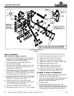
Assembly Instructions
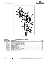
A detailed listing of parts for this kit is provided on page 8
for kits. Use the list that is for your specific Third Function
Valve Kit as a checklist to inventory parts received.
Please contact your local Land Pride dealer for any
missing hardware.
Direction Reference
All directional references are made from the operator
seat while facing the direction the machine will operate.
Directional Arrows Used in Illustrations
Initial Preparations
WARNING
!
To avoid serious injury or death: Hydraulic fluid under high
pressure can penetrate the skin and/or eyes causing a serious
injury. Wear protective gloves and safety glasses or goggles
when working with hydraulic systems.
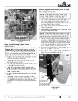
The steps listed below must be followed before installing
this kit:
1. If the front loader is not attached to the tractor, skip to
step 8. Otherwise, continue with step 2 below.
2. Lower loader arms fully down, turn tractor off, and
relieve all hydraulic pressure to the front loader
couplers by operating the loader control lever(s) in all
directions.
3. Having released all hydraulic pressure, lock the
control lever(s) from moving.
4. Remove all mechanical connections securing the
front loader to the tractor.
5. Disconnect all hydraulic lines from the front loader.
6. Refer to your tractor/loader Operator’s Manual for
additional unhooking instructions.
7.
Restart tractor and slowly back away from the loader.
8. Park tractor on a flat, level surface. Put tractor in park
or set park brake, turn off engine, and remove switch
key to prevent unauthorized starting.
9. Place chocks in front and back of the tractor’s left rear
wheel.
10. As a safety precaution, disconnect the battery cable
from the battery’s negative (-) terminal. Move
negative cable away from the terminal to avoid
accidental contact.
U
D
B
F
R
L
U = up
L = left
B = back
D = down
R = right
F = front
KEY:
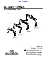
For B2320 Kubota Tractors with LA304 Loader and
B2620 Kubota Tractors with LA364 Loader
Third Function Valve Kit
#380-340A Installation Instructions
Manual No. 380-151M
7/8/20