background image

1

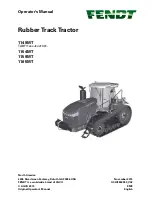
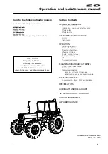
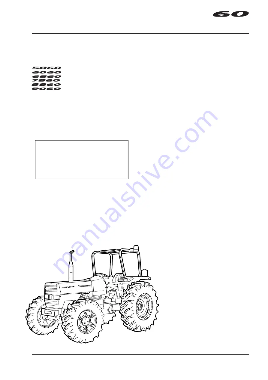
Operation and maintenance manual

Valid for the following tractor models:

For tractors with safety frame model:

Table of Contents

GENERAL INFORMATION

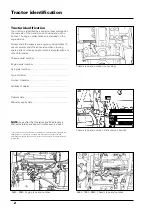
Tractor identification.

Introduction, warranty and safety notes.

Safety notes.

Safety decals.

INSTRUMENTS AND CONTROLS

Controls.

Instruments.

OPERATION

Starting the engine.

Starting the tractor.

Adjusting wheel track.

Wheels and tyres.

Auxiliary control valves.

Three point linkage.

Lift.

Towing attachments.

MAINTENANCE AND ADJUSTMENTS

Routine maintenance table.

Running-in.

Tractor maintenance:

Greasing, oil level and changes.

Adjustments - axles, brakes and wheels.

ELECTRICAL SYSTEM

Replacements - fuses, bulbs and batteries.

SPECIFICATIONS

LUBRICANTS AND FUELS CHART

'CE' DECLARATION OF CONFORMITY

HITCHING IMPLEMENTS

ALPHABETICAL INDEX

Publication N. 3534157 M95

Printed in 1998

 (depending on the market)

CALIFORNIA

Proposition 65 Warning

Diesel engine exhaust and

some of its constituents are known to

the State of California to cause

 cancer, birth defects, and other reproductive harm.

Summary of Contents for 5860

Page 1: ...point linkage Lift Towing attachments MAINTENANCE AND ADJUSTMENTS Routine maintenance table Running in Tractor maintenance Greasing oil level and changes Adjustments axles brakes and wheels ELECTRICA...

Page 2: ...umbers to ensure prompt and efficient service when ordering spare parts or when asking for technical explanations or other information Chassis serial number Engine serial number Cab serial number Type...

Page 3: ...mbols and their terms 6 Introduction 6 Advice for the operator 6 Comply with the safety regulations 7 Safety frame 8 Precautions for safe operation 8 Tractor maintenance 11 Starting 11 Working in safe...

Page 4: ...d in particularly adverse conditions e g in heavy soils or very muddy conditions contact your local dealer for specific instructions Failure to do so may render null and void the warranty on your trac...

Page 5: ...devices are included Despite this fact many accidents happen every year that could have been avoided if the operator had taken greater care when handling farming machinery and equipment Read this manu...

Page 6: ...l before you start using the tractor You must follow these safety instructions as they take you step by step through your working day In reading this section you will notice that illustrations are use...

Page 7: ...s is illustrated at the end of this section If a used tractor has been purchased refer to the illustrations at the end of this section to ensure that all the safety warning decals are in the correct p...

Page 8: ...e seat belt for damage Damaged belts must be replaced Damaged safety frames or cabs If the tractor has rolled over and the safety frame or the cab have been damaged they must be replaced in order to e...

Page 9: ...NGINE READ THIS MANUAL CAREFULLY AND LEARN TO USE THE MACHINE CORRECTLY IN CONDITIONS OF ABSOLUTE SAFETY Fig 1 4 IF THERE IS ANYTHING IN THIS MANUAL THAT YOU DO NOT UNDERSTAND ASK SOMEONE WHO HAS MORE...

Page 10: ...d top up if required Perform all maintenance and adjustment procedure outlines in the Routine Maintenance section Check that the PTO safety locking devices are connected Check that the PTO guard and d...

Page 11: ...Tighten to the pre scribed torque values Check the brakes regularly and adjust if neces sary Make sure that the brakes are correctly adjusted and that they are both coupled together especially when u...

Page 12: ...nd cause serious injury Make sure front frame counterweights wheel weights and ballast are used as recommended by the manu facturer NEVER add counterweights to compen sate for an overload it is better...

Page 13: ...nyone When working make sure other people stay away Never let anyone pass or stand under a raised implement Fig 1 10 NEVER lift objects that are not securely held in the bucket When using a loader avo...

Page 14: ...es smoothly and gradually When going down a slope use the throttle to slow the tractor engine and use the same gear that you would use going up the slope Shift into gear before you start to do down En...

Page 15: ...UT if possible If you have to drive forwards proceed slowly and with caution Drive straight up or down a slope never across it When you drive up or down a slope keep the heavy end of the tractor point...

Page 16: ...you Operate your tractor with the wheels set at the widest possible setting that the work you are doing allows To adjust track settings refer to the Operation section Reduce your speed when operating...

Page 17: ...Clean all the reflectors and road lights front and rear and make sure they are in working order The highway code Take all due precautions when driving on public roads WARNING DO NOT allow any passeng...

Page 18: ...components carried out by the specialized staff of your dealer If however service operations must be undertaken on parts containing asbestos contact your dealer for advice on handling such components...

Page 19: ...asured for the tractor to operate efficiently during tillage On normal terrain in good operating conditions wheel slip should be between 4 and 10 On loose soil wheel slip can exceed 12 If wheel slip i...

Page 20: ...er brakes and greater ballast on the rear wheels in order to ensure sufficient braking power on the rear axle Consult your dealer for any further requirements there may be for special applications 9 O...

Page 21: ...ase when it is limited to a diminished ability to perceive acute sounds music bells or the spoken voice when there is a background noise it can only be detected by means of an audio metric test Pulsat...

Page 22: ...n only when engine is cold 3648 447 M1 On mudguard for tractors with safety belts WARNING Danger of being crushed When safety belts are worn the safety frame must always be in the upright position 355...

Page 23: ...lectrocution Always disconnect the negative terminal of the battery before removing the solenoid cover and before servicing the electrical system 3559 553 M1 On quick coupling support DANGER Risk of e...

Page 24: ...y notes SAFETY DECAL LOCATIONS WEO markets For this decal pack order part N 3559 552 M93 3559559M1 3559554M1 3648447M1 3647157M1 3559556M1 3559555M1 3648152M1 3647158M1 3559558M1 3559553M1 3647032M1 3...

Page 25: ...ing or ad justment Couple brake pedals to gether for road travel Use flashing warning lights and SMV emblem when on public roads except where prohibited by law Always drive with care and attention 355...

Page 26: ...yes and face from battery Cigarettes flames or sparks could cause battery to explode Do not charge or use booster cables or adjust post connections without proper instructions or training POISON cause...

Page 27: ...tes SAFETY DECAL LOCATIONS NORTH AMERICA For this decal pack order part N 3558702M94 24d 3558706M1 3558707M1 3558708M1 3558712M1 3558705M1 3648153M1 3648446M1 3558711M1 3558703M1 3558710M1 3558709M1 3...

Page 28: ...Safety notes 24e Page left intentionally blank...

Page 29: ...25 Instruments and controls Table of contents Page N Instruments and controls 26 Instrument panel 27 Warning lights 27 Operation indicator lights 28 Control panel 29 Seat 30 Miscellaneous 30...

Page 30: ...ator pedal 6 Supplementary spool valve levers for remote controls 7 Hydraulic lift levers 11 Gearshift clutch lever 12 Speed selector lever Consult page 35 for the options with reverse shuttle 13 Gear...

Page 31: ...on and hydraulic system filter blockage red If installed Brake fluid level low indicator if installed Red warning light for low pressure in trailer brake system if fitted and depending on market Engin...

Page 32: ...ows excessive engine speed The 25 and 30 Km h speed indications are respectively given at 1850 RPM and 2200 RPM and correspond to tractor speeds in fast fourth gear The three internal coloured scales...

Page 33: ...ff 1 Side lights on 2 Contact for lower and driving beams D Rear field light switch Operates with switch C in positions 1 and 2 0 Off 1 Field light on E Hazard light switch Fig 4 always operative 0 Of...

Page 34: ...ly accessible from the driver s seat 1 Rigid suspension knob turned clockwise Soft suspension knob turned anticlockwise Regulating the distance Release the seat by means of lever 3 to move it backward...

Page 35: ...eration 33 Gearbox operation 34 Power Take off 36 Brakes 38 Differential lock 39 2WD 39 4WD front axle regulating the steering angle 39 Adjusting wheel track 40 Wheels and tyres 43 Ballast 44 Towing a...

Page 36: ...operate Cold weather starting temperatures below 0 C Caution when outdoor temperatures drop to around or below 0 C 32 F check the cooling circuit and if necessary add the recommended antifreeze Proce...

Page 37: ...e engine Turn the accelerator control to the Idling position and pull the relative stop knob fully out When the engine is at a standstill turn the ignition key to the OFF position to disconnect all el...

Page 38: ...from one range to the other disengage the clutch stop the tractor and shift the speed range selector lever To change from one gear to the other within the same speed range including the reverse simply...

Page 39: ...20 overdrive 28 or reverse shuttle The figure on the right illustrates the various combinations that can be obtained depending on the type of gearbox mounted NOTE The selector levers must be in the c...

Page 40: ...to it Warning fix the drawbar in the central position when using implements that are driven by the PTO of the tractor Power take off The tractor is equipped with a power take off D Fig 13 that complie...

Page 41: ...ge the PTO with the relative control When working with the PTO only disengage the relative clutch for the time strictly required to carry out the various manoeuvres Warning when using the PTO and the...

Page 42: ...ng system for the front axle This type of braking system is of particular use when the tractor is driven on the road or when it it used in mountain areas The front brakes are only operated when both b...

Page 43: ...by regulating the stop pin on the reduction gear to obtain a maximum steering angle of 40 or 50 The adjustments are made as indicated in the diagram 4WD front axle with Hydrolock differential lock On...

Page 44: ...bolts 1 and washers that hold the sliding ends Remove the bolt 2 that fastens the track rod clamp Slide the RH end sideways and fix it at the required track width Repeat the same operation for the LH...

Page 45: ...shown in the table below Torque the wheel nuts 1 between 18 and 20 da Nm Fig 29 Fig 21 POSITIONS A B C D E F G H W 8 28 1350 1438 1538 1626 1578 1666 1766 1854 W 8 24 1352 1440 1540 1628 1580 1668 17...

Page 46: ...ging the position of the wheel discs The torque wrench setting for the nuts and bolts 1 Fig 22 that fix the rim to the wheel hub is 28 da Nm 210 lbf ft It is extremely important to ensure that the tyr...

Page 47: ...lts B in a diagonal and progressive way until reaching a final driving torque of 28 daNm 209 lbf ft It is extremely important to ensure that the tyre is inflated to the established pressure since this...

Page 48: ...Kg 132 lb each an overall 240 Kg 529 lb can be applied Ballasting the front axle If heavy implements that might destabilize the tractor are hitched to the lift cast iron plates can be added to the fr...

Page 49: ...on used to three quarters fill each tyre This solution gives protection at tempera tures down to 20 The percentage of calcium chloride must be increased when the temperatures are lower In relation to...

Page 50: ...lution after it has completely cooled To limit the acicity add 1 of soda in proportion to the calcium chloride used after inflating the tyre thoroughly rinse any metal parts that may have been wetted...

Page 51: ...positions so that the drawbar remains as horizontal as possible This keeps the weight over the front axle and improves tractive force Class A swinging drawbar The tractor can be equipped with a class...

Page 52: ...he axis of the PTO shaft Front pull hook The tractor may be equipped with a front pull hook 4 Fig 31 for emergency pulling operations from the front and for towing the tractor Fig 31 5860 6060 6860 78...

Page 53: ...couplings must be the same standard size as the three point linkage of the tractor to prevent the whole assembly from being subjected to irregular stress during work caused by dimensional incompatibi...

Page 54: ...oupled to the ball ends of the bar Now adjust the length of the top link and couple it LH vertical lift rod Fig 36 37 The fork 3 of the lh vertical lift rod can be regulated in two ways by turning the...

Page 55: ...the lift in position control mode when transporting implements hitched to the three point linkage Warning Always use the lift in position control mode when an implement is hitched or unhitched to or f...

Page 56: ...54 2 lb Work in position control mode Position control mode allows the implement to be brought to and kept in a determined position which ever this may be This includes the highest and lowest position...

Page 57: ...h run Move the control lever A back to raise the implement at the end of each run Control lever travel must be very slight when working at shallow depths To prevent the implement from digging into the...

Page 58: ...ke the tractive force of the tractor more regular Even partial use of draft control mode leads to work depth variations and it is thanks to these that the tractive force of the tractor is kept at a mo...

Page 59: ...the valve lever E from the horizontal position upwards 2 and lock it in place again with the relative mechanism 4 Control the external ram by operating the lever A that controls the lift arms Move th...

Page 60: ...onstant and automatic regulation of the work position The floating position is obtained by moving the lever A fully forwards to second position where it will remain locked at end of travel If released...

Page 61: ...Valve clearance 60 Engine cooling circuit 62 Power lift hydraulic circuits and transmission oil 63 Main clutch and gearbox 63 PTO clutch 63 Brakes 64 Rear final drives 68 4WD front axle 68 Steering ci...

Page 62: ...ing circuit 36 Check oil levels in gearbox front axle differential and front and rear side final drives Variable 9 10 11 12 Change oil in gearbox 2 front axle differential and front and rear side fina...

Page 63: ...ar chains break down WARNING It is advisable to change the oil after 6 months even if the established work hours have not been reached during that period WARNING To ensure the engine is correctly lubr...

Page 64: ...in dirt or water Fill the tractor s fuel tank Fig 49 in the evening after finishing the day s work This prevents condensation from forming inside the tank The fuel filter cap d is fitted with a gauze...

Page 65: ...s out of the bleeder Re tighten the bleeder 3 Slacken the bleed screw 3 of the injection pump in a similar way Fig 51 52 53 4 Slacken off the other bleeder screw 4 by a couple of turns and loosen at l...

Page 66: ...s with compressed air Warning Never remove the radiator cap when the engine is hot You could be scalded Unscrew the radiator cap slowly for part of its turn to release pressure before removing it comp...

Page 67: ...ake sure that the hydraulic services connected to the tractor use the same type of oil as the transmission Mixing different oil types can lead to damage to the system Clutch Adjusting the gearshift cl...

Page 68: ...pedal play is within the required values 3 5 cm using the adjuster 2 again if this is not the case 7 Repeat the above procedure for the other side of the tractor On completion of the adjustment make...

Page 69: ...en off the check nut and tighten the adjuster 1 Turn the wheel on the same side by hand at the same time while continuing to tighten the adjuster Stop when the wheel opposes resistance to being turned...

Page 70: ...d left actuators have been bled A Fig 64 bleed the compensation tube that connects them B 7 Depress the left hand pedal until the action stiffens Unscrew the bleed screw 1 connected to the right hand...

Page 71: ...is specific case the bleeder screw is on the valve unit so that air can also be bled from the piloting duct 2 Press both pedals at the same time and loosen the two bleeder screws 4 Fig 68 on each of t...

Page 72: ...d pads so that the caliper plungers completely retract Take out the worn pads 2 one at a time and fit in new ones NOTE remove and replace one pad a time and immediately fit the new one in to prevent t...

Page 73: ...28 and diesel fuel op 33 filters twice at 100 hour intervals After this change the oil and diesel fuel filters at the intervals specified in the Routine Maintenance Guide Hydraulic lift thoroughly wa...

Page 74: ...heck the level of the electrolyte in the battery every 3 or 5 mounths depending on ambient temperature This must be done with the engine switched off the battery cold and with the tractor parked on fl...

Page 75: ...an not often enough 1 Radiator Make sure that the level of the coolant reaches the reference mark on the reservoir Top up if necessary 4 3 Air filter Clean all parts of the filter C with gasoline Dry...

Page 76: ...ate by means of adjuster 3 Consult the Operation and Maintenance manual 12 11 13 Front differential housing Make sure that the oil reaches the edge of the plug 1 Top up through the same plug using oil...

Page 77: ...he recommended type of grease two points 24 23 Front axle drive shaft bearing Inject the recommended grease Non driving front axle pivot pin Inject with the recommended type of grease 2 points 18 100...

Page 78: ...ance values 28b Engine oil filter Mod 5860 6060 Replace the filter cartridge 1 Smear the seal of the new filter with oil and screw hand tight perform together with op 27 EVERY 250 HOURS SERVICE 33 31...

Page 79: ...m Open the drain cocks from the radiator A and cylinder block B and allow the fluid to drain out Flush out the cooling circuit see Maintenance chapter EVERY 1000 HOURS SERVICE 41 Front axle epicyclic...

Page 80: ...Maintenance 76 Page left intentionally blank...

Page 81: ...the alternator and fan belts 78 Battery 78 Starter motor 79 Alternator 79 Headlights 79 Fuses to protect the electrical system 80 Wiring diagram 81 Instrument panel wiring diagram 82 Wiring diagram fo...

Page 82: ...pports Battery Your tractor is equipped with a Maintenance Free battery which will rarely need checking for electrolyte level or charge under normal conditions However you are advised to check the lev...

Page 83: ...unless it is properly con nected If the battery is not connected high voltages can build up inside the alternator that can be extremely dangerous if the output terminal is touched Make sure that all...

Page 84: ...ht AP Lh rear side light AQ Resistance AR Diode 1N4007 AS Diff lock switch if installed AT Pressure sensor for trailer brake hydraulics CA CB CC CD Instrument panel connectors Cable colours A Pale blu...

Page 85: ...trical system 81 Fig 76 Wiring diagram F P F P S F P F P S B G A A H C D I E F L M N CA CB Q T U Z V CC CD S O P AS AI AH AF AD R AA AL AO AV AP AB AC AV AG AM AQ AE AT M N O COBO SWITCHES HELLA SWITC...

Page 86: ...Fast PTO engaged indicator 14 Diff lock indicator not used 15 Indicator light for simultaneous control from 16 to 22 and 3 16 Not used 17 Low pressure in hydraulic trailer brake circuit indicator ligh...

Page 87: ...ystem 83 Fig 78 Start up enabling line with PTO disengaged 2 4 1 3 1 4 way connector 2 Wires from start up enabling switch to rear harness connector on dashboard 3 Jordan instrument connector A 4 2 wa...

Page 88: ...Electrical system 84 Page left intentionally blank...

Page 89: ...cuit 95 Three point linkage 95 Towing devices 95 Seat 95 Bonnet 95 Safety frame 95 Electrical system 95 Instrument panel 96 Optional extras 96 Noise level 97 12x12 gearbox with reverse shuttle 98 24x1...

Page 90: ...Wheelbase mm E Max length with front ballast and links mm F Ground clearance under front axle mm G Width mm H Front track mm I Rear track mm 5860 6060 2 WD 4 WD 2 WD 4 WD 7 50 16 12 4 24 7 50 18 12 4...

Page 91: ...G Width mm H Front track mm I Rear track mm 6860 7860 8860 2 WD 4 WD 2 WD 4 WD 2 WD 4 WD 7 50 18 12 4 R 24 9 00 16 12 4 R 24 9 00 16 13 6 R 24 16 9 R 30 16 9 R 30 18 4 R 30 18 4 R 30 16 9 R 34 16 9 R...

Page 92: ...ghts C A V with removable cartridge and bleeder plug 1 2 3 1 2 3 2645630 2645A013 190 bar 210 bar ISKRA cold weather starter In oil bath with separator prefilter Technical specifications Engine Type M...

Page 93: ...ins Diesel 4 stroke direct injection A4 236 A4 236 A4 248 4 vertical in line 4 vertical in line 4 vertical in line 98 43 mm 98 43 mm 101 1 mm 127 mm 127 mm 127 mm 3865 cc 3865 cc 3865 cc 16 1 16 1 16...

Page 94: ...material Gearbox clutch Mod 5860 6060 6860 cerametallic Mod 7860 8860 cerametallic PTO clutch organic A 12 304 8 mm double clutch with gearshift clutch in cerametallic and PTO clutch in organic mater...

Page 95: ...d 18 25 19 15 20 04 4th 26 90 28 22 29 55 Reverse 1st 4 16 4 37 4 57 2nd 6 54 6 86 7 19 3rd 8 26 8 67 9 08 4th 12 19 12 79 13 00 6060 Speeds in Km h with engine at top power rate 2250 RPM REAR TYRES R...

Page 96: ...4 discs 7860 8860 5 discs Hydrostatic braking control by means of two pedals on the operator s right the two pedals can be coupled together by a locking device to provide simultaneous braking action o...

Page 97: ...he wheel hubs A front axle with mechanically controlled differential lock can be supplied on request Transmission unit on the gearbox with infinitely meshed gears and 29 31 reduction ratio Bevel gear...

Page 98: ...R 28 128 A8 W 12 28 1 6 12 4 R 24 119 A8 W 10 24 1 6 16 9 R 30 6Pr W 14L 30 1 3 7 50 18 6Pr 5 50 F 18 2 3 13 6 R 36 127 A8 W 11 36 1 6 7 50 20 6Pr 5 00 F 20 2 3 18 4 R 30 142 A8 W 15L 30 PAVT 1 6 7 5...

Page 99: ...8860 Cold starting surge at 18 C in 30 seconds 600 A Charge for 20 hours 92 Ah Charge reserve 170 mm Hydraulic power lift Controls draft position and in the Intermix mode both draft and position Also...

Page 100: ...m Mod 6860 7860 8860 on request 12 304 8 mm dry double disc clutch with cerametallic disc and organic PTO disc Sun shader roof Technical specifications Lights Front lights including Two double filamen...

Page 101: ...to noise during continuative use of the tractor be 85 dBA or more the operator must take the necessary precautions as indicated in Art 40 41 42 43 and 44 of Legislative Decree D L 277 of 15 08 1991 Re...

Page 102: ...74 6 30 6 59 6 32 6 54 3rd 7 84 8 20 8 51 7 96 8 32 7 99 8 26 4th 11 56 12 10 12 56 11 75 12 28 11 78 12 19 1st 9 74 10 20 10 54 9 90 10 34 9 93 10 27 2nd 15 31 16 02 16 62 15 55 16 25 15 60 16 14 3r...

Page 103: ...ward speeds and 12 reverse speeds as indicated below 12 forward speeds reduced by 20 from 1 4 Km h to 25 0 Km h 12 standard forward speeds from 1 7 Km h to 29 5 Km h 12 standard reverse speeds from 1...

Page 104: ...3 40 3 53 3 30 3 45 3 31 3 42 4th 4 79 5 02 5 20 4 87 5 09 4 88 5 05 1st 3 91 4 09 4 24 3 97 4 15 3 98 4 12 2nd 6 14 6 43 6 67 6 24 6 52 6 26 6 48 3rd 7 76 8 12 8 43 7 88 8 24 7 91 8 18 4th 11 45 11 9...

Page 105: ...71 3rd 3 25 3 40 3 53 3 30 3 45 3 31 3 42 4th 4 79 5 02 5 20 4 87 5 09 4 88 5 05 1st 3 91 4 09 4 24 3 97 4 15 3 98 4 12 2nd 6 14 6 43 6 67 6 24 6 52 6 26 6 48 3rd 7 76 8 12 8 43 7 88 8 24 7 91 8 18 4t...

Page 106: ...3rd 4 19 4 38 4 55 4 25 4 44 4 26 4 41 4th 6 17 6 47 7 00 6 27 6 56 6 29 6 51 1st 5 04 5 27 5 46 5 11 5 35 5 13 5 31 2nd 7 91 8 28 8 59 7 99 8 40 8 06 8 35 3rd 10 00 10 46 10 86 10 15 10 62 10 19 10...

Page 107: ...ere permitted by the Highway Code the tractor can be equipped with a gearbox with overdrive able to obtain a maximum speed of approx 40 Km h and which when combined with the creeper with 1 5 12 reduct...

Page 108: ...9 8 15 8 43 2nd 11 97 13 15 13 64 12 76 13 34 12 80 13 25 3rd 15 12 16 61 17 23 16 12 16 85 16 17 16 74 4th 22 30 24 49 25 40 23 77 24 84 23 84 24 67 1st 1 64 1 71 1 78 1 66 1 74 1 67 1 72 2nd 2 57 2...

Page 109: ...3 10 17 2nd 15 15 15 86 16 46 15 40 16 09 15 44 15 98 3rd 19 15 20 04 20 79 19 45 20 33 19 51 20 19 4th 28 22 29 55 30 65 28 67 29 97 28 77 29 76 1st 2 11 2 20 2 29 2 14 2 24 2 15 2 22 2nd 3 31 3 47 3...

Page 110: ...9 2 61 2 73 2 62 2 71 3rd 3 25 3 40 3 53 3 30 3 45 3 31 3 42 4th 4 79 5 02 5 20 4 87 5 09 4 88 5 05 1st 3 91 4 09 4 24 3 97 4 15 3 98 4 12 2nd 6 14 6 43 6 67 6 24 6 52 6 26 6 48 3rd 7 76 8 12 8 43 7 8...

Page 111: ...107 Table of contents Page N Technical specifications 108 Routine maintenance 109 Ground speed table 109 7860HC 8860 HC...

Page 112: ...bar 688 mm 688 mm under front axle 745 mm 625 mm Turning radius Mod 7860 with brakes 3 75 m 5 62 m without brakes 4 32 m 6 40 m Mod 8860 with brakes 3 85 m 5 70 m without brakes 4 40 m 6 50 m Track wi...

Page 113: ...oil to drain out Pour in oil of the recommended type through fill plug A until reaching the level of the plug itself Fig 83 Fig 84 Ground speed table with 13 6R38 tyres and 2200 RPM engine rate Range...

Page 114: ...I GL 5 Any temperature HD GEAR OIL MOBILUBE GX 90 GEAR OIL SPIRAX BP Hypogear LOT CX ROTRA HP MIL 2105 D EP 90 140 MOBILUBE HD 90 GP 80 W 90 HD 80 W 90 Oil 80 W 90 80 W 90 API GL 5 Any temperature HD...

Page 115: ...cal specifications to be observed when hitching farming or industrial implements are enclosed with the Operation and Maintenance Manual together with a drawing of the hitch points for implements and t...

Page 116: ...l 0522 656111 10 lines Fax 0522 660725 Landini Fabbrico Telex 530024 date To LANDINI S p A Via G Matteotti 7 42042 FABBRICO REGGIO EMILIA Model FRONT REAR TOTAL Reference weight Drawing DYNAMIC LOADS...

Page 117: ...tyres Front tyres WEIGHTS WITH IMPLEMENTS HITCHED Rear tyres TarE Kg HITCH POINTS on the front axle Kg Front N Bolts meas Center N Bolts meas on the rear axle Kg Rear N Bolts meas HITCHED IMPLEMENTS M...

Page 118: ...PLANE M 16x2 16 HOLES 4WD WHEELBASE VIEW FROM B ADJUSTABLE ADJUSTABLE 5 HOLES 6 HOLES 4 HOLES LOADED RADIUS DIFF AXLE REAR WHEEL SHAFT LIFTING CAPACITY 1900 KG 3 POINT LINKAGE LAYOUT CLASS II 8 HOLES...

Page 119: ...OLES 4WD WHEELBASE VIEW FROM B ADJUSTABLE ADJUSTABLE 5 HOLES 6 HOLES N 4 FORI LOADED RADIUS DIFF AXLE REAR WHEEL SHAFT LIFTING CAPACITY 1900 KG SCHEMA ATTACCO A 3 PUNTI CAT II 8 HOLES 4 HOLES 12 HOLES...

Page 120: ...LES 4 HOLES LOADED RADIUS DIFF AXLE REAR WHEEL AXLE 3 POINT LINKAGE LAYOUT CLASS II 8 HOLES 4 HOLES 12 HOLES 22 HOLES DETAIL OF REAR PART OF TRACTOR DRIVING AXLE ENGINE RPM 2 WD 4 WD DRIVING AXLE 8 HO...

Page 121: ...ES 4 HOLES LOADED RADIUS DIFF AXLE REAR WHEEL AXLE 3 POINT LINKAGE LAYOUT CLASS II 8 HOLES 4 HOLES 12 HOLES 22 HOLES DETAIL OF REAR PART OF TRACTOR DRIVING AXLE ENGINE RPM 2 WD 4 WD DRIVING AXLE 8 HOL...

Page 122: ...6 48 Km h 30 06 Km h 13 6 80 Km h 14 8 18 Km h 15 10 20 Km h 16 12 07 Km h 17 8 47 Km h 18 10 17 Km h 19 13 31 Km h 20 15 98 Km h 21 16 82 Km h 22 20 14 Km h 23 24 80 Km h 24 29 76 Km h Power take of...

Page 123: ...k Hydralock Equipment available as spares 1000 RPM PTO at 1914 RPM engine rate 540 1000 2nd and 3rd single and double acting supplementary control valves with automatic release 8 front weights 36 Kg e...

Page 124: ...ay code 17 Hitching implements 112 114 Hydraulic circuit oil level and changing 63 Hydraulic circuit steering 68 Hydraulic power lift with mechanical control 52 Hydraulically controlled trailer brake...

Page 125: ...Starting the tractor 32 Systems inspections 10 T Technical specifications 86 Technical specifications 2WD front axle 92 Technical specifications 4WD front axle 93 Technical specifications brakes 92 T...

Page 126: ...122 To ensure long and efficient service from your tractor use only spare parts and lubricants recommended by...

Page 127: ...6 48 Km h 30 06 Km h 13 6 80 Km h 14 8 18 Km h 15 10 20 Km h 16 12 07 Km h 17 8 47 Km h 18 10 17 Km h 19 13 31 Km h 20 15 98 Km h 21 16 82 Km h 22 20 14 Km h 23 24 80 Km h 24 29 76 Km h Power take of...

Page 128: ...k Hydralock Equipment available as spares 1000 RPM PTO at 1914 RPM engine rate 540 1000 2nd and 3rd single and double acting supplementary control valves with automatic release 8 front weights 36 Kg e...

Page 129: ...MAX TORQUE SPEED 1400 RPM 1400 RPM 1400 RPM IDLING SPEED 750 RPM 750 RPM 750 RPM CYLINDER LINERS CAST IRON DRY EXTRACTABLE VALVE OVERHEAD VALVES TAPPET GAP HOT ENGINE 0 25 MM COLD ENGINE 0 30 MM FUEL...

Page 130: ...ay code 17 Hitching implements 112 114 Hydraulic circuit oil level and changing 63 Hydraulic circuit steering 68 Hydraulic power lift with mechanical control 52 Hydraulically controlled trailer brake...

Page 131: ...2 Systems inspections 10 T Technical specifications 86 Technical specifications 2WD front axle 92 Technical specifications 4WD front axle 93 Technical specifications brakes 92 Technical specifications...

Page 132: ...123 To ensure long and efficient service from your tractor use only spare parts and lubricants recommended by...

Reviews: