background image

®

LANDOLL COMPANY, LLC

1900 North Street

Marysville, Kansas 66508


(785) 562-5381


800-428-5655


~


WWW.LANDOLL.COM

Pulvi-Mulcher

3631-30 Model

Operator’s Manual

F-982-0223

Summary of Contents for 3631-30

Page 1: ... LANDOLL COMPANY LLC 1900 North Street Marysville Kansas 66508 785 562 5381 800 428 5655 WWW LANDOLL COM Pulvi Mulcher 3631 30 Model Operator s Manual F 982 0223 ...

Page 2: ...Manuals for 3631 30 Pulvi Mulcher Manual Number Manual Type F 982 Operator s Manual F 981 Parts Manual F 984 3631 25 3631 30 Coil Tine Harrow Kit Instruction Sheet ...

Page 3: ...sibly death DO NOT operate or perform any maintenance tasks on this equipment until you have completed the following 1 Receive proper training to operate this equipment safely 2 Read and understand the operator s manual 3 Be thoroughly trained on inspection and repair procedures ...

Page 4: ......

Page 5: ... 3 Prepare for Emergencies 1 3 High Pressure Fluid Safety 1 3 Safety Chain 1 4 Decals 1 5 2 Assembly Frame Installation 2 1 Rockshaft Installation 2 6 Tire and Wheel Installation 2 7 Rockshaft Cylinder and Transport Lock Installation 2 8 Drawbar Installation Manual Jack 2 10 Drawbar w Hydraulic Jack Installation 2 12 Drawbar Leveling Installation 2 14 Manual Holder and Wrenches Installation 2 16 W...

Page 6: ... 2 58 Wing Tooth Tube Installation 2 59 Wing Shank Mounting Dimensions 2 60 Wing Tooth Control Mounting Dimensions 2 62 Wing Tooth Control Installation 2 65 Plumb Wing Tooth Control Cylinders 2 68 Purging the Tooth Control Cylinders 2 68 Wing Shank Installation 2 69 Wing 2 Row Harrow Installation 2 70 Roller Clamp Spacer Installation 2 74 Center Rear Scraper Installation 2 76 Wing Rear Scraper Ins...

Page 7: ...r Turnbuckle Adjustment 3 9 Coil Tine Harrow 3 10 Land Leveler V Leveler Optional 3 11 Scraper Adjustment 3 12 Transport 3 13 4 Maintenance General Torque Specifications 4 1 Hydraulic Fitting Torque Specifications 4 2 Fasteners 4 2 Tires 4 3 Wheel Hub Bearing Maintenance 4 3 Hydraulic Maintenance 4 3 Lubrication Maintenance 4 4 Roller Axle Assembly 4 5 Clamp Tightening 4 5 Clamp End Spacers Option...

Page 8: ...iv F 982 0223 TABLE OF CONTENTS ...

Page 9: ...ons in this manual are determined by facing the direction the implement will travel during field operation unless otherwise stated Owner Assistance If customer service or repairs are needed contact your Brillion dealer They have trained personnel parts and service equipment specially designed for Brillion products Your implement s parts should only be replaced with Brillion parts If items covered ...

Page 10: ...te and local laws When transporting the implement on a road or highway use adequate warning symbols reflectors lights and slow moving vehicle sign as required Slow moving tractors and towed implements can create a hazard when driven on public roads They are difficult to see especially at night Do not tow an implement that when fully loaded weighs more than 1 5 times the weight of the towing vehicl...

Page 11: ... prevent injury Transport Locks installed Do not make adjustments or lubricate the machine while it is in motion Make sure all moving parts have stopped Understand the procedure before doing the work Use proper tools and equipment Protective Equipment Wear protective clothing equipment appropriate for the job Avoid loose fitting clothing Because prolonged exposure to loud noise can cause hearing i...

Page 12: ...e chain to the tractor drawbar support or specified anchor location Never attach the chain to an intermediate support Allow only enough slack in the chain to permit turning The distance from hitch pin to attachment point or intermediate support point should not exceed 9 inches See Figure 1 2 If the distance from the drawbar pin to either the front or rear chain attachment point exceeds 9 inches In...

Page 13: ...CTOR IS MOVING WHEN SERVICING IN RAISED POSITION PLACE BLOCKING UNDER ROLLERS WITH WINGS FOLDED AND WEIGHT ON CENTER ROLLER THE IMPLEMENT IS DRAWBAR LIGHT ITEM 4 5J859 ITEM 6 2 573 010198 ITEM 7 2 573 010335 ITEM 8 3J675 ITEM 10 528933 ITEM 11 528938 ITEM 12 528934 ITEM 13 170510 ITEM 14 144193 BLEED THE AIR FROM WING LIFT CYLINDERS BEFORE OPERATING FAILURE TO DO SO WILL CAUSE MACHINE DAMAGE SEE O...

Page 14: ...1 6 F 982 0223 SAFETY INFORMATION TABLE OF CONTENTS Figure 1 4 Decal Locations 1 of 5 3630 25 Decal Drawbar 12 1 2 4 5 12 ...

Page 15: ...SAFETY INFORMATION F 982 0223 1 7 TABLE OF CONTENTS Figure 1 5 Decal Locations 2 of 5 Front View Rear View 13 9 10 13 13 15 11 10 11 11 11 7 7 14 6 12 12 10 10 ...

Page 16: ...1 8 F 982 0223 SAFETY INFORMATION TABLE OF CONTENTS Figure 1 6 Decal Locations 3 of 5 Side Views 3630 30NC Decal CtrSide 14 8 17 12 17 14 8 12 13 13 9 9 16 12 8 8 16 12 18 20 ...

Page 17: ...SAFETY INFORMATION F 982 0223 1 9 TABLE OF CONTENTS Figure 1 7 Decal Locations Right Hand Wing 4 of 5 3630 30NC Decal RHWing 3 3 9 8 8 8 8 ...

Page 18: ...1 10 F 982 0223 SAFETY INFORMATION TABLE OF CONTENTS Figure 1 8 Decal Locations Left Hand Wing 5 of 5 3630 30NC Decal LHWing 3 8 8 8 3 9 8 ...

Page 19: ...sembly See Figure 2 4 2 Using blocks or other supports block up the Right Hand Center Frame approximately 36 Ensure that it is secure and cannot topple The Rockshaft should be positioned approximately halfway between the supports 3 Attach the Front and Rear Roller Frame Assembly to the Right Hand Center Frame Assembly The Right Hand Center Frame Assembly consists of an outside and inside tube Asse...

Page 20: ...2 2 F 982 0223 ASSEMBLY TABLE OF CONTENTS Figure 2 1 Front Roller Support Front Roller Support Bolt 3 4 10 x 2 1 2 Locknut 3 4 10 Bolt 3 4 10 x 2 1 2 Locknut 3 4 10 Front Roller Frame Asm ...

Page 21: ...ASSEMBLY F 982 0223 2 3 TABLE OF CONTENTS Figure 2 2 Center Frame Dimensions 79 11 16 36 79 11 16 36 79 11 16 79 11 16 Rear Front Top View ...

Page 22: ...Figure 2 3 Right Hand Center Frame Front Locknut 3 4 10 U Bolt 3 4 10 Right Hand Frame Asm Bolt 3 4 10 x 2 1 2 Rockshaft Locknut 3 4 10 U Bolt 3 4 10 Bolt 3 4 10 x 2 1 2 Rear Roller Frame Asm Front Roller Frame Asm Locknut 3 4 10 Locknut 3 4 10 ...

Page 23: ... U Bolt 3 4 10 Locknut 3 4 10 Bolt 3 4 10 x 2 1 2 Rear Wing Rest Tube Front Cross Tube Bolt 3 4 10 x 2 1 2 Locknut 3 4 10 Bolt 3 4 10 x 2 1 2 3630 30NC OpFrameBoth Front Flat Washer 3 4 Locknut 3 4 10 Locknut 3 4 10 Bolt 3 4 10 x 2 1 2 Flat Washer 3 4 Locknut 3 4 10 ...

Page 24: ...t Cap Bearing and fasten with 3 4 10 x 2 Bolts and Locknuts Ensure the UHMW Bearings are seated properly into Caps and Frame Mounts Repeat for the remaining Lift Cap bearings Tighten bolts See Page 4 1 Figure 2 5 Rockshaft Installation Do not attempt to lift heavy parts such as the frame rock shaft and pull hitch manually Use a hoist or a fork lift to move these parts into position Bolt 3 4 10 x 2...

Page 25: ... Install the 3 4 16 Flange Nuts and tighten to 50 ft lbs using the sequence in Figure 2 7 Then tighten to full torque of 220 ft lbs Figure 2 6 Stud Tightening Sequence NOTE Torque will drop after the first 10 hours of operation Check the nuts for proper torque after this interval and re tighten them Figure 2 7 Tire and Wheel Assembly Use a torque wrench to assure proper torque Insufficient torque ...

Page 26: ... pieces Place 1 x 1 1 2 x 14ga Washer on the outside by the clevis pin hole Secure with 3 16 x 2 Cotter Pin Check to ensure there is no binding 4 Attach the Transport Lock Bracket to the top of the Rear Frame tube aligning it with the 4 1 2 x 14 Hydraulic Cylinder place the Clamp under the tube and insert two 5 8 11 x 4 1 2 Bolts through the top of the Transport Lock Bracket and through the Clamp ...

Page 27: ...nut 3 4 10 Bushing 11 16 Long Flat Washer 3 4 Bolt 3 4 10 x 2 Bolt 5 8 11 x 4 1 2 Transport Lock Lever Transport Lock Bracket Transport Lock Clamp Washer 1 x 1 1 2 x 18ga Cotter Pin 3 16 x 2 Clevis Pin 1 x 2 1 2 Washer 1 25 x 1 875 x 14ga Transport Lock Pin 1 1 4 3 Hole Roll Pin 3 8 x 2 1 4 Hair Pin Clevis Pin 1 2 x 4 Hydraulic Cylinder 4 1 2 x 14 Washer 2 1 2 x 1 1 4 x 3 4 ...

Page 28: ... 4 x 1 7 8 x 14ga Washer on each end of pin and secure with 5 16 x 2 Roll Pins 4 Attach the Jack to the Drawbar using four 3 4 10 x 2 1 2 Bolts and Locknuts 5 Attach the Hose Holder Bracket to the Drawbar using 3 4 10 x 7 Bolt with flange up thread one 3 4 10 Serrated Flange Nut onto the bolt place the Hose Holder Bracket over the bolt and against the flange of the installed nut Thread the second ...

Page 29: ...er Hose Holder Bracket HHCS 1 4 20 x 1 HHCS 3 8 16 x 5 Full Thread Hex Nut 3 8 16 Hose Holder Clamp Hose Holder Wing Nut Drawbar Bolt 3 4 10 x 2 1 2 Bolt 3 4 10 x 7 Pin 1 7 16 x 10 1 4 Washer 1 1 2 x 2 1 4 x 10ga Roll Pin 3 8 x 2 1 4 Hitch Leveler Washer 1 1 4 x 1 7 8 x 14ga Pin 1 1 4 x 8 1 4 Roll Pin 5 16 x 2 Washer 1 1 4 x 2 1 2 x 12ga Pin 1 1 4 x 12 1 2 Roll Pin 5 16 x 2 Flat Washer 1 4 ...

Page 30: ...1 1 4 Lock Washer and 1 1 4 7 Hex Nut into the rear hole of the Drawbar Center Bracket 6 Install Double Pilot Check Valve Fittings See Figure 2 11 7 Assembly the Double Pilot Check Valve to the Valve Bracket with 3 8 16 x 2 1 4 Bolt 3 8 Flat Washer and 3 8 16 Flange Locknut 8 Attach the Valve Bracket and Hose Support to the Drawbar Center Bracket with 1 2 13 x 6 Bolt and 1 2 13 Flange Locknuts 9 I...

Page 31: ...Clamp Double Pilot Check Valve Adapter 8 O Ring to 6 Tube Flange Locknut 3 8 16 Locknut 1 2 13 Flange Locknut 1 2 13 Elbow 90 8 SAE x 6 JIC Hose Asm 1 4 x 21 Bolt 1 2 13 x 6 Bolt 3 8 16 x 2 1 4 Thrust Washer 1 34 Slotted Pin 5 16 x 2 1 2 Jack Pivot Tube Jack Base Jack Tube Flat Washer 1 Pin 1 x 5 1 2 Slotted Pin 5 16 x 2 Thrust Washer 1 34 Slotted Pin 5 16 x 2 1 2 Jack Pivot Tube Flat Washer 1 Slo...

Page 32: ... Nut that is holding the Hitch Leveler together so that the outer portion can pivot rearward 4 Attach the base end of 4 x 16 Hydraulic Cylinder onto the Front Cross Tube Lug top hole with the vendor supplied hardware Pivot the rod end of the Cylinder between the Leveler Mount and insert 1 x 10 1 8 Pin though components Place a 1 x 1 1 2 x 14ga Washer on each end of the Pin and secure with 5 16 x 2...

Page 33: ...ASSEMBLY F 982 0223 2 15 TABLE OF CONTENTS Table provided for general use NOTES ...

Page 34: ...two Open End Box End Wrenches to the side of the Center Frame and the two Open End Wrenches to the side of the Hitch Leveler Secure with 1 4 x 1 1 4 Lynch Pins See Figure 2 14 Figure 2 13 Manual Holder and Wrenches 3630 30NC OpWrenchManualCan Bolt 1 4 20 x 1 Flat Washer Manual Holder Locknut 1 4 20 Frame Hitch Leveler Lynch Pin Open End Wrenches Open End Box End Wrenches Lynch Pin ...

Page 35: ...low for rod movement when purging the Fold Circuit NOTE To reduce the Wing down float droop when turning around with the machine raised install Optional Wing Fold 4 x 29 3 4 Hydraulic Cylinders with Internal Stop instead of the standard Wing Fold 4 x 30 Hydraulic Cylinders See Figure 2 88 Figure 2 14 Wing Fold Hydraulic Cylinder Installation RH Front Frame Lug Hydraulic Cylinder 4 x 30 3630 30NC O...

Page 36: ...2 18 F 982 0223 ASSEMBLY TABLE OF CONTENTS Table provided for general use NOTES ...

Page 37: ...he Lift Circuit with machine raised requires approximately 4 9 gallons of hydraulic oil and with machine lowered requires 4 5 gallons of hydraulic oil Tightening Procedure For JIC 37 Swivel Female Nuts 1 Check flare and seat for defects 2 Lubricate the connection 3 Install hoses without twists 4 Hand tighten until connection bottoms 5 Using 2 wrenches to prevent twisting rotate the swivel nut 2 wr...

Page 38: ...assembly 4 Route hoses down right side of drawbar Wrap the Tooth Control System hoses near the Tractor Tips with black hose wrap Figure 2 16 Simplified Hydraulic Tooth Control Schematic 6LPSOL HG7RRWK WUO6FKHPDWLF G OLQGHU 5H3KDVLQJ 141864 RVH VP 3 8 x 175 Elbow 90 8MJ x 8MOR LPLW 9DOYH 211344 RVH VP 3 8 x 226 GDSWHU 8MJ x 10MOR G OLQGHU 5H3KDVLQJ Elbow 90 8MJ x 8MOR 211345 RVH VP 3 8 x 170 181799...

Page 39: ...ng Unfolded Wing Folded Wrap Hoses near Hinge Pin both sides 211320 Hose Asm 3 8 x 300 Bolt 5 16 18 x 5 1 2 Locknut 5 16 18 Limit Valve Bolt 3 8 16 x 5 All Thread Washer Flat 3 8 Hose Clamp Locknut 3 8 16 Hose Holder Clamp Nut 3 8 16 Bolt 3 8 16 x 5 All Thread 211321 Hose Asm 3 8 x 220 181799 Hose Asm 3 8 x 74 141864 Hose Asm 3 8 x 175 Hyd Cyl RePhasing 4 1 2 x 8 211345 Hose Asm 3 8 x 170 3630 30N...

Page 40: ...J x 08MOR 181799 Hose Asm 3 8 x 74 Hyd Cyl RePhasing 4 1 2 x 8 Hyd Cyl RePhasing 4 1 2 x 8 141864 Hose Asm 3 8 x 175 211320 Hose Asm 3 8 x 300 211344 Hose Asm 3 8 x 226 Limit Valve 08MJ x 08MOR Hyd Cyl RePhasing 4 x 8 141881 Hose Asm 3 8 x 136 212345 Hose Asm 3 8 x 170 3630 30NC ToothCtrlHydSchematic 141881 Hose Asm 3 8 x 136 211321 Hose Asm 3 8 x 220 212345 Hose Asm 3 8 x 170 Elbow 90 08MJ Elbow ...

Page 41: ...tall the Fold Down Pressure Valve and Relief Valve fittings and hoses See Figures 2 21 and 2 22 7 Route hoses to tractor from Fold Down Pressure Valve and down right side of drawbar Wrap Fold System hoses near the Tractor Tips with Yellow Hose Wrap 8 Install Gauge into top of Fold Down Pressure Valve 9 Secure all hoses with tie wraps Figure 2 20 Fold Down Pressure Valve Restrictors are installed i...

Page 42: ... Gauge 117259 Hose Asm 3 8 x 48 202702 8 8S Adapter 8MJ x 8MOR 195196 Check Valve 141828 Male Coupler to Tractor Hyd Remote 211319 Hose Asm 3 8 x 200 116492 Hose Asm 3 8 x 128 8J650 Relief Valve 234545 Manifold 195198 Filter 195197 Valve Press Reducing Relieving 2062 8 8S Adapter 90 8MJ x 8MOR 202702 8 8S Adapter 8MJ x 8MOR 202702 8 8S Adapter 8MJ x 8MOR ...

Page 43: ...47 Hose Asm 3 8 x 93 166171 Hose Asm 3 8 x 114 Bolt 3 8 16 x 5 All thread Washer Flat 3 8 Hose Clamp Locknut 3 8 16 Tower Manifold Nut 1 2 13 Bolt 1 2 13x 4 169055 Hose Asm 3 8 x 93 123079 Hose Asm 3 8 x 62 163781 Hose Asm 3 8 x 17 211316 Hose Asm 3 8 x 49 Flat Washer 1 2 147582 Hose Asm 3 8 x 24 Relief Valve Bolt 1 4 20 x 2 1 4 Flat Washer 1 4 Locknut 1 4 20 Flat Washer 3 8 Lockwasher 3 8 Bolt 3 ...

Page 44: ...Valve Schematic 141826 Restrictor 1 16 163781 Hose Asm 3 8 x 17 202702 8 8S Adapter 8MJ x 8MOR 71508984 Hose Asm 3 8 x 42 211316 Hose Asm 3 8 x 49 169055 Hose Asm 3 8 x 93 Manifold 123079 Hose Asm 3 8 x 62 2071 8 8S Adapter Elbow 203005 8 8S Tee 203450 Limit Valve 2072 8 8S Elbow 2062 8 8S Adapter 90 Hyd Cyl 4 x 30 Hyd Cyl 4 x 30 Hyd Cyl 4 x 30 211316 Hose Asm 3 8 x 49 141826 Restrictor 1 16 71508...

Page 45: ...ASSEMBLY F 982 0223 2 27 TABLE OF CONTENTS Table provided for general use NOTES ...

Page 46: ... 8 Cylinder fittings CAUTION 5 Install Restrictor and Branch Tee into the base end and O Ring Branch Tee into the rod end of the 4 x 16 cylinder See Figures 2 26 and 2 27 6 Install Lift Cylinder and Hitch Leveler Hoses 7 Secure all hoses with Cable Ties and Tie Wraps Wrap the Lift Circuit System hoses near the Tractor Tips with Blue Hose Wrap 8 Install Wings if not already assembled See Wing to Fr...

Page 47: ...se Asm 1 2 x 178 241061 Hose Asm 1 2 x 240 211314 Hose Asm 1 2 x 160 71508954 Hose Asm 3 8 x 22 203425 Hose Asm 3 8 x 33 Hyd Cyl 4 x 8 Hyd Cyl 4 x 16 211313 Hose Asm 3 8 x 42 Bolt 5 16 18 x 2 197698 Hose Asm 1 2 x 188 Blue Hose Wrap 197698 Hose Asm 1 2 x 198 Hose Clamp Bolt 3 8 16 x 5 All thread Washer Flat 3 8 Locknut 3 8 16 51316 14 Hose Asm 1 2 x 56 1 2 Manifold Flat Washer 1 2 Nut 1 2 13 21131...

Page 48: ...se Asm 3 8 x 22 203425 Hose Asm 3 8 x 33 211313 Hose Asm 3 8 X 42 Hyd Cyl 4 x 16 Hyd Cyl 4 x 8 2062 8 8S Elbow 8MJ x 8MOR 164435 Counter Balance Valve 137486 Adapter 10MJ x 10MOR 1 007 010025 Plug 8MOR 125863 Adapter 10MJ x 8MOR 125863 Adapter 10MJ x 8MOR 1412153 Hose Asm 1 2 x 123 1412151 Hose Asm 1 2 x 10⁵ 51316 14 Hose Asm 1 2 x 56 1 2 211314 Hose Asm 1 2 x 160 211315 Hose Asm 1 2 x 178 211306 ...

Page 49: ...fittings Recheck tractor reservoir oil level With machine raised lift circuit requires 4 9 gallons of hydraulic oil With machine lowered requires 4 5 gallons of hydraulic oil Purge Fold Circuit With fold cylinders disconnected from wings and blocked up to allow for rod movement connect fold circuit hoses to tractor Ensure tractor reservoir is full of manufacturer s recommended oil Extend fold cyli...

Page 50: ...2 32 F 982 0223 ASSEMBLY TABLE OF CONTENTS Table provided for general use NOTES ...

Page 51: ...els See Figure 2 30 1 After marking the tubes for the shank locations slide the 170 Tooth Tubes into the Tooth Tube Bearings See Figure 2 31 2 Position Tooth Tubes in the proper lateral position to the frame before continuing See Figure 2 32 Figure 2 28 Tooth Tube Bearing Position for Roller with 24 Wheels Frame Bottom Position ToothTubeBrgNotched24 Tooth Tube Tooth Tube Bearing ...

Page 52: ...time Figure 2 29 Center Frame Shank Mounting Dimensions 5 REF 6 1 2 REF 3 1 2 REF 0 13 31 49 85 67 121 103 139 157 170 REF 5 0 5 1 2 23 1 2 3 1 2 41 1 2 149 1 2 131 1 2 113 1 2 167 1 2 77 1 2 59 1 2 95 1 2 0 2 1 2 20 1 2 38 1 2 56 1 2 74 1 2 92 1 2 128 1 2 146 1 2 164 1 2 170 REF 110 1 2 170 REF Tooth Tube Tooth Tube Bearing Tooth Tube Tooth Tube Bearing RH LH Front C L C L Top View Center Frame S...

Page 53: ...nsions 5 6 1 2 170 3 Places 2 1 8 2 Places 2 1 8 2 Places 2 36 Tooth Tube Bearing RH LH Front Pin 1 x 6 1 2 Tooth Control Clamp Tooth Control Clamp Tooth Control Clamp w cutout Tooth Control Clamp Tooth Control Clamp w cutout Tooth Control Tube Tooth Tube Top View Center Frame Tooth Control Linkage All dimensions are for reference only 3630 30NC OpToothCtrlDim ...

Page 54: ...e Tooth Tube Secure with 5 8 11 x 5 Bolts and Locknuts Right Side 1 Attach a Tooth Control Bracket on the top of the right Front Tooth Tube by sliding a Clamp Plate into the Tooth Control Bracket Slot and under the Tooth Tube Secure with 5 8 11 x 5 Bolts and Locknuts Do Not tighten at this time See Figures 2 33 and 2 34 2 Lay the Cylinder Rod Clevis between the Tooth Control Bracket Lugs Position ...

Page 55: ... 30NC OpToothCtrl Tooth Control Tube Clamp Plate Pin 1 x 6 1 2 Roll Pin 5 16 x 2 Locknut 5 8 11 Tooth Control Bracket Roll Pin 5 16 x 2 4 Hole Plate Tooth Control Clamp Hydraulic Cylinder 4 1 2 x 8 Bolt 5 8 11 x 2 Bolt 5 8 11 x 5 Flat Washer 1 Bolt 5 8 11 x 5 Pin 1 x 6 1 2 Locknut 5 8 11 Flat Washer 1 ...

Page 56: ...See scraper section on page 2 76 Front installation is similar to rear It is easier to install shanks while machine is raised Assemble Points to Shanks as shown in Figure 2 34 Mount the Shanks to the Tooth Control Tubes using two 1 2 13 x 5 Bolts and Locknut See Figure 2 31 for Center Shank Mounting Dimensions Figure 2 32 Shank Installation 3630 OpShankPoints Bolt 1 2 13 x 5 Locknut 1 2 13 Lock Wa...

Page 57: ...ASSEMBLY F 982 0223 2 39 TABLE OF CONTENTS Table provided for general use NOTES ...

Page 58: ... Stop Assembly through the Depth Stop Guide to the Depth Stop Clamp Position the Depth Stop Assembly over the Depth Stop Clamp Lug and align the Top Hole of the Depth Stop Clamp for the 24 Roller Wheels Insert and secure with 5 8 11 x 2 3 4 Bolt and Flanged Locknut See Figure 2 35 4 Ensure that the Depth Stop Clamp is positioned correctly and that the Depth Stop Assembly moves freely when turning ...

Page 59: ...rol Installation 7 1 2 9 1 8 Depth Stop Clamp Depth Stop Assemble Middle Tooth Tube Limit Valve Mount Front LH Frame Front Cross Tube Position for Rollers with 24 Wheels Depth Stop Assemble Top View Shank Depth Control All dimensions are for reference only Depth Stop Clamp ...

Page 60: ... x 3 Tube into the cut out portion of the Harrow Adjustment Tube and insert a 1 2 13 U Bolt on each side See Figures 2 37 and 2 38 Check Harrow position in relation to the Frame and secure with Flat Washer and Locknut 3 Install a 1 2 13 x 5 Bolt and Locknut into the top hole of each Harrow Adjustment Tube 4 Remove from one end of the Frame Adjuster Mount the Harrow Height Adjuster Handle Tube Slid...

Page 61: ...nterHarrow Roll Pin 5 16 x 2 1 2 Harrow Height Adj Handle Pin 1 x 7 5 16 Flat Washer 3 8 Locknut 3 8 16 Bolt 3 8 16 x 2 3 4 Flat Washer 1 1 2 Tube Harrow Adjust Harrow Assembly Locknut 1 2 13 Locknut 5 8 11 U Bolt Harrow Adjust Tube Bolt 1 2 13 x 5 FRONT Flat Washer 1 1 2 Flat Washer 5 8 Hair Pin Cotter 3 16 ...

Page 62: ...igure 2 36 Center Frame 2 Row Harrow Dimensions 160 2 4 2 4 LH Rear RH Harrow Adjustment Tube 3x3 Harrow Tube Harrow Adjustment Tube Harrow Assembly 3x3 Harrow Tube U Bolt 1 2 13 Harrow Assembly Harrow Adjustment Tube 3630 30NC OpCenterHarrowDim ...

Page 63: ...ASSEMBLY F 982 0223 2 45 TABLE OF CONTENTS Table provided for general use NOTES ...

Page 64: ...p Harness noting that the connectors marked with Green Tape is Right Side and Yellow Tape is Left Side Plug the Lamp Harness into the Flasher Control Module 5 Route Green Tape cords along the right side of the Rear Roller Frame Plug the 3 Prong Cord into the Red Lamp Plug the 2 Prong Cord into the Amber Lamp 6 Repeat for the Left Side Yellow Tape 7 Plug the 7 Pin Harness 4 Pin Weather pack plug in...

Page 65: ...40ft Amber LED Bolt 1 4 20 x 1 3 4 Flat Washer 1 4 Light Bracket Locknut 1 4 20 5HÀHFWRU Asm Red LED Tywrap 8 U Bolt Flasher Control Module AG Harness 40ft Locknut 1 4 20 Cable Tie Bolt 1 4 20 x 1 1 2 LED Light Harness LED Light Harness Bolt 1 4 20 x 1 3 4 Flanged Locknut 5 8 11 5HÀHFWRU Asm Flanged Locknut 5 8 11 Flat Washer 1 4 ...

Page 66: ...ensions 1 61 1 61 97 11 16 97 11 16 2 SMV SMV Mount C L C L 5HÀHFWRU Assembly Red Lamp PEHU Lamp 5HÀHFWRU Assembly with Hole Light UDFNHW Light UDFNHW 5HDU 9iew RH LH 1 2S OHFW LP 5HÀHFWRU Assembly Red Lamp Light UDFNHW PEHU Lamp 5HÀHFWRU Assembly with Hole Light UDFNHW ...

Page 67: ...e Wing Rest Bracket over the outside of the Bearing Hanger Assemble the Wing Rest Bracket and Bearing Hanger onto the Wing Frame with 3 4 10 X 2 3 4 Bolts and Locknuts Tighten the 3 4 10 Bolts at this time 3 Secure the end of the Wing Rest to the Wing Frame with 5 8 11 U Bolts and Flanged Locknuts Figure 2 41 Wing Rest and Bearing Hanger Front 3630 25 OpWingBrgHanger Bolt 1 2 13 x 3 1 2 Flat Washe...

Page 68: ...ween the Inner Hinge Link and the Wing Frame Hinge Plates Insert 1 1 4 x 8 1 4 Pin into the side of the Wing Hinge Plate with the Keeper Plate so the Roll Pin fits into the slot See Figure 2 44 Place two Flat Washers on the end of the Pin Secure with 5 16 x 2 Roll Pin 5 Swing the Inner and Outer Hinge Links together along with the Hydraulic Cylinder Rod End Clevis Place a 1 1 4 x 2 1 2 x 12ga Thru...

Page 69: ...nge Bearing Roll Pin 5 16 x 2 Roll Pin 5 16 x 2 Pin 1 1 4 x 8 1 4 Hyd Cyl Thrust Washer 1 1 4 x 2 1 2 x 12ga Flat Washer 1 1 4 Thrust Washer 1 1 4 x 2 1 2 x 12ga Pin 1 1 4 x 10 7 8 Roll Pin 5 16 x 2 Existing Pin Existing Hardware 3630 30NC OpWingHingeFrame Outer Hinge Link Flat Washer 1 1 4 Thrust Washer 1 1 4 x 2 1 2 x 12ga Thrust Washer 1 1 4 x 2 1 2 x 12ga Flat Washer 1 1 4 ...

Page 70: ...d from Hub and Spindle 3 Remove the eight 5 8 18 Nuts from the Hub Install the Tire and Wheel Assembly onto the hub The Pulvi Mulcher Wing Lifts use 320 70R15 tires and should be inflated to 70 PSI See Figure 2 49 4 Re Install the 5 8 18 Nuts and tighten to 50 ft lbs using the sequence in Figure 2 48 Then tighten to full torque of 130 150 ft lbs 5 Repeat Steps 3 4 for opposite wing Figure 2 46 Stu...

Page 71: ...MOR x 10MJ Bolt 3 4 10 x 2 Hyd Cyl 4 x 14 UHMW Bearing RH Wing Lift Hub and Spindle Right Hand Left Hand Tire and Wheel Asm Locknut 1 2 13 x 5 Bolt 1 2 13 x 5 Locknut 3 4 10 Lift Cap Bearing LH Wing Lift Lift Cap Bearing Bolt 1 2 13 x 5 Locknut 3 4 10 Locknut 1 2 13 x 5 Hub and Spindle ...

Page 72: ...2 54 F 982 0223 ASSEMBLY TABLE OF CONTENTS Table provided for general use NOTES ...

Page 73: ...nsert 5 8 11 x 1 3 4 Bolts into Frame Bearing Hanger Place a Dirt Shield on each end of the Roller Stub Shaft so that the cupped portion will be towards the Bearing Slide the Bearing onto the Roller Stub Shaft Lift up while supporting the Roller Assembly so that the Bearing can be assembled with Locknuts onto the outside of the Frame Bearing Hanger Bearings should be tight against the Bearing Hang...

Page 74: ... 48 Left Hand Wing Roller Installation Front 3630 30NC OpLHWingRoller Bearing Dirt Shield Shim Washer 14ga Wheel Asm Shim Washer 11ga Flat Top Washer Lock Washer 1 Bolt 5 8 11 x 1 3 4 Bolt 1 8 x 2 1 4 Flange Bearing Locknut 5 8 11 3 8 Thick Washer 1 ID ...

Page 75: ...nd Wing Roller Installation Front 3630 30NC OpRHWingRoller 3630 25 OpLHWingRoller Bearing Dirt Shield Shim Washer 14ga Wheel Asm Bolt 5 8 11 x 1 3 4 Bolt 1 8 x 2 1 4 Locknut 5 8 11 3 8 Thick Washer 1 ID Lock Washer 1 Flat Top Washer Shim Washer 11ga Flange Bearing ...

Page 76: ...ng Frames with the vendor supplied hardware Adjust the Anchor Nuts to achieve a distance of approximately 6 1 2 from the Center Frame Tube to the center of the Cylinder Pin See Figure 2 53 Figure 2 50 Wing Tooth Control Cylinder Installation 6 1 2 REF RH Wing Frame Hyd Cylinder 4 x 8 Nuts 6 1 2 REF LH Wing Frame Cylinder Anchor Hyd Cylinder 4 x 8 Nuts 3630 30NC OpWingToothCtrlCyl Cylinder Anchor ...

Page 77: ...bes in the proper lateral position to the wing frame before continuing See Figures 2 59 and 2 60 3 Place Stops on Tooth Control Tube against Tooth Tube Bearing to prevent Tooth Control Tube from sliding right or left Secure with 1 2 13 x 4 1 2 Bolts and Locknuts See Figures 2 56 2 57 and 2 58 Figure 2 51 Wing Tooth Tube Bearing Position for Roller with 24 Wheels Figure 2 52 Wing Tooth Control Tube...

Page 78: ...ubes at this time Figure 2 53 Left Hand Wing Shank Mounting Dimensions 0 4 8 1 2 22 40 58 76 80 REF 0 5 1 2 23 1 2 41 1 2 59 1 2 77 1 2 80 REF 4 0 4 22 14 1 2 40 58 76 80 REF Tooth Tube Tooth Tube Tooth Tube Bearing Tooth Tube Stop Tooth Tube Bearing Tooth Tube Bearing Stop Stop Front Hinge LH 3630 30NC OpLHWingShankDim Top View LH Wing Shank Locations Tooth Tube Bearing ...

Page 79: ...5 1 2 4 23 1 2 41 1 2 59 1 2 77 1 2 80 REF 0 4 22 76 40 58 80 REF 8 1 2 0 14 1 2 22 4 80 REF 76 58 40 Stop Tooth Tube Bearing Tooth Tube Bearing Tooth Tube Bearing Stop Tooth Tube Tooth Tube Tooth Tube Bearing Stop Tooth Tube RH Front Hinge Top View RH Wing Shank Locations 3630 30NC OpRHWingShankDim ...

Page 80: ... 45 1 2 14 1 2 4 80 3 Places 2 1 16 Tooth Tube Tooth Tube Tooth Tube Bearing Tooth Tube Bearing Tooth Tube Tooth Tube Bearing Tooth Tube Bearing Front Hinge LH Pin 1 x 6 1 2 Tooth Control Clamp Cylinder T ooth Control Clamp w cutout 3630 30NC OpLHToothCtrlDim Top View LH Wing Tooth Control Linkage All dimensions are for reference only Stop Stop Stop ...

Page 81: ...3 Places 4 2 1 16 Tooth Tube Bearing Tooth Tube Bearing Tooth Tube Bearing Tooth Tube Tooth Tube Tooth Tube Bearing Tooth Tube RH Front Hinge Cylinder Tooth Control Clamp Pin 1 x 6 1 2 Tooth Control Clamp w cutout Top View RH Wing Tooth Control Linkage All dimensions are for reference only 3630 30NC OpRHWingToothCtrlDim Stop Stop ...

Page 82: ...2 64 F 982 0223 ASSEMBLY TABLE OF CONTENTS Table provided for general use NOTES ...

Page 83: ...ghten hardware after positions of clamps and tube have been verified See Figure 2 59 Right Side 1 Attach a Tooth Control Bracket on the top of the right Front Tooth Tube by sliding a Clamp Plate into the Tooth Control Bracket Slot and under the Tooth Tube Fasten with 5 8 11 x 5 Bolts and Locknuts Do Not tighten at this time See Figure 2 62 2 Lay the Cylinder Rod Clevis between the Tooth Control Br...

Page 84: ...gToothCtrl Tooth Control Tube Flat Washer 1 Clamp Plate Pin 1 x 6 1 2 Locknut 5 8 11 Roll Pin 5 16 x 2 4 Hole Plate Tooth Control Clamp Bolt 5 8 11 x 2 Hydraulic Cylinder 4 x 8 RePhasing Bolt 5 8 11 x 5 Tooth Control Bracket Tooth Control Bracket Bolt 5 8 11 x 5 Roll Pin 5 16 x 2 Pin 1 x 6 1 2 Locknut 5 8 11 ...

Page 85: ...trl Tooth Control Tube Flat Washer 1 Bolt 5 8 11 x 5 Clamp Plate Locknut 5 8 11 Tooth Control Bracket Roll Pin 5 16 x 2 Pin 1 x 6 1 2 4 Hole Plate Tooth Control Bracket Hydraulic Cylinder 4 x 8 RePhasing Tooth Control Clamp Flat Washer 1 Bolt 5 8 11 x 5 Bolt 5 8 11 x 2 Locknut 5 8 11 Pin 1 x 6 1 2 Roll Pin 5 16 x 2 ...

Page 86: ...e Machine Slowly raise the Shanks and continue to hold the hydraulic lever until all Tooth Control Cylinders are fully retracted Lower and raise the shanks to verify that all cylinders are working simultaneously throughout the stroke If the cylinders are not working evenly or together fully retract the tooth control cylinders and continue to hold the lever to purge any remaining air 3 Do not loose...

Page 87: ...on on page 2 78 Front Scraper installation is similar to rear It is easier to install shanks while machine is raised 2 Assemble Points to Shanks as shown in Figure 2 64 3 Mount the Shanks to the Wing Tooth Control Tubes using two 1 2 13 x 5 Bolts and Locknut See Figures 2 57 and 2 58 for Left and Right hand Shank Mounting Dimensions Figure 2 60 Wing Shank Installation 3630 OpShankPoints Bolt 1 2 1...

Page 88: ...tory assembled Lift Harrow Assembly and slide the Harrow 3 x 3 Tube into the cut out portion of the Harrow Adjustment Tube and insert a 1 2 13 U Bolt on each side Check Harrow position in relation to the Frame and secure with Flat Washer and Locknut See Figures 2 67 and 2 68 3 Install a 1 2 13 x 5 Bolt and Locknut into the top hole of each Harrow Adjustment Tube Figure 2 61 Left Hand Wing Harrow F...

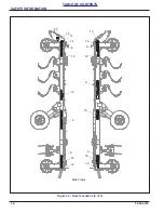
Page 89: ...ASSEMBLY F 982 0223 2 71 TABLE OF CONTENTS Figure 2 62 Right Hand Wing Harrow ...

Page 90: ...LE OF CONTENTS Figure 2 63 Left Hand Wing Harrow Dimension 8 1 2 14 1 2 2 1 4 Rear Hinge LH Front Hinge LH U Bolt 1 2 13 3x3 Harrow Tube Harrow Assembly Harrow Adjustment Tube 3x3 Harrow Tube Harrow Assembly Harrow Adjustment Tube ...

Page 91: ...BLE OF CONTENTS Figure 2 64 Right Hand Wing Harrow Dimension 13 3 4 7 3 4 2 Rear Hinge RH Front Hinge RH U Bolt 1 2 13 Harrow Assembly Harrow Assembly 3x3 Harrow Tube Harrow Adjustment Tube 3x3 Harrow Tube Harrow Adjustment Tube ...

Page 92: ... the axle clamps so that it s against the wheel 3 If there is a gap between the Axle Clamp and the Wheel Stop install the appropriate Clamp Spacer with 3 8 16 x 1 3 4 Bolt and Locknut See Figure 2 69 See Maintenance Section for a list of other Kits that are available See Figures 4 5 and 4 6 Figure 2 65 Roller Clamp Spacer Installation 201442 201443 ClampEndSpacerKit Axle Spacer Axle Spacer Axle Sp...

Page 93: ...ASSEMBLY F 982 0223 2 75 TABLE OF CONTENTS Table provided for general use NOTES ...

Page 94: ... a 3 8 16 U Bolts Scrapers and Flanged Locknuts Center the Scraper between the Notched Wheels and adjust the Scraper so that there is a 1 4 gap between the Scraper and Notched Wheel Tighten 3 Attach the Scrapers to the Scraper Tube with 3 8 16 U Bolts and Flanged Locknuts ensure that the scrapers are centered between the Notched Wheels along with a 1 4 gap between the Scraper and Notched Wheel Fig...

Page 95: ...TABLE OF CONTENTS Figure 2 67 Center Rear Scraper Mounting Dimensions 5 16 7 1 2 60 4 1 2 60 Center Scraper Bracket Center Scraper Bracket LH RH Center Rear Scrapers Frame 5 16 3 4 Tube Scraper 3630 30NC OpCenterRearScraperDim ...

Page 96: ... the Scraper between the Notched Wheels and adjust the Scraper so that there is a 1 4 gap between the Scraper and Notched Wheel Tighten 3 Attach the Scrapers to the Scraper Tube with 3 8 16 U Bolts and Flanged Locknuts ensure that the scrapers are centered between the Notched Wheels along with a 1 4 gap between the Scraper and Notched Wheel Figure 2 68 Wing Rear Scraper Installation 3630 30NC Wing...

Page 97: ...ure 2 69 Wing Rear Scraper Mounting Dimensions 3 8 16 5 8 60 Wing Scraper Bracket LH Wing Rear Scrapers LH Hinge LH Wing Frame 3 8 19 5 8 60 Wing Scraper Bracket RH Hinge RH Wing Frame RH Wing Rear Scrapers 3 4 3 8 Scraper Tube 3 4 3 8 Tube Scraper ...

Page 98: ...n similar to Rear Scrapers See Page 2 76 Refer to the Mounting Dimension See Figure 2 75 Figure 2 70 Center Front Scrapers Installation Optional 3630 30NC CtrFrontScraper Tube U Bolt 3 8 16 Scraper U Bolt 5 8 11 U Bolt 3 8 16 Flanged Locknut 3 8 16 Flanged Locknut 5 8 11 Scraper Bracket ...

Page 99: ...nsions Figure 2 71 Center Front Scraper Mounting Dimensions 4 1 2 60 7 1 2 60 5 16 Center Scraper Bracket Center Scraper Bracket Frame Center Optional Front Scrapers View from the inside of the machine looking forward LH RH 5 16 3 4 Scraper Tube 3630 30NC OpCenterFrontScraperDim ...

Page 100: ...efer to the Mounting Dimensions See Figure 2 77 Figure 2 72 Wing Front Scraper Installation Optional 3630 30NC WingFrontScraper Flanged Locknut 5 8 11 U Bolt 5 8 11 Wing Scraper Bracket U Bolt 3 8 16 Scraper Tube Wing Scraper Bracket U Bolt 3 8 16 Scraper Tube U Bolt 5 8 11 Flanged Locknut 5 8 11 Flanged Locknut 3 8 16 Flanged Locknut 3 8 16 ...

Page 101: ... 16 5 8 60 Wing Scraper Bracket LH Wing Optional Front Scrapers View from the inside of the machine looking forward LH Hinge Frame 19 5 8 3 8 60 Wing Scraper Bracket RH Wing Optional Front Scrapers View from the inside of the machine looking forward RH Hinge Frame 3 4 3 8 Scraper Tube 3 8 3 4 Tube Scraper 3630 30NC OpWingFrontScraperDim ...

Page 102: ...2 84 F 982 0223 ASSEMBLY TABLE OF CONTENTS Table provided for general use NOTES ...

Page 103: ...213908 Figure 2 74 Rear 3 Bar Coil Tine Harrow Kit Optional 3630 30NC RearHarrowOption Wing Harrow Arm Assembly Wing Harrow Arm Assembly Harrow Asm 7 Tine 3 Row Harrow Asm 6 Tine 3 Row Harrow Asm 5 Tine 3 Row Harrow Arm Assembly Harrow Asm 5 Tine 3 Row 221593 221593 221594 198621 168801 168800 168799 ...

Page 104: ... the 3 x 3 tube into the Arm Notch Position 5 8 11 U Bolt onto the 3 x 3 Tube and through the Harrow Arm Assembly Secure with Thick Washers and Flange Nuts See Figure 2 80 Figure 2 75 Harrow Arm Installation to Frame Figure 2 76 Harrow Arm Installation to Harrow Assembly Do not work on or under this machine unless securely blocked and supported by a hoist or tractor or by other sufficient means Do...

Page 105: ...SSEMBLY F 982 0223 2 87 TABLE OF CONTENTS Figure 2 77 Center Rear Harrow Mounting Dimensions 6 38 6 38 14 1 8 13 3 4 Harrow Assembly 168801 Harrow Assembly 168800 221594 Harrow Arm Assembly without Lift ...

Page 106: ...LY TABLE OF CONTENTS Figure 2 78 Rear Wing Harrow Mounting Dimensions 6 3 4 34 7 1 4 Harrow Assembly 168799 RH Wing Frame Rear Tube 6 3 4 33 1 2 6 3 4 Harrow Assembly 198621 LH Wing Frame Rear Tube 221593 Harrow Arm Assembly ...

Page 107: ...ers up into the mount slot and insert 1 2 13 x 3 Bolt On the opposite side place the 1 x 1 1 2 Bushing over the bolt and into the opening Secure with Flat Washer and Locknut 3 Insert 3 8 x 2 1 2 Cotter Pin into the upper hole and spread Figure 2 79 Land Leveler Installation Optional 3630 30NC LandLevelerOption U Bolt 3 4 10 x 5 25 32 x 7 1 4 Wing U Bolt 3 4 10 x 6 13 16 x 7 3 4 Center Flat Washer ...

Page 108: ... CONTENTS Figure 2 80 Land Leveler Center Mounting Dimensions 2 9 16 20 11 16 43 2 9 16 20 11 16 43 Leveler Mount Leveler Mount LH RH LH Leveler RH Leveler Center Section Land Leveler LH Frame RH Frame 3630 30NC OpLandLevelerCenterDim ...

Page 109: ...e 2 81 Land Leveler Wing Mounting Dimensions 9 1 2 22 1 2 44 LH Wing Leveler Leveler Mount Hinge LH Wing Frame LH Wing Land Leveler 9 1 2 22 1 2 44 RH Wing Leveler Hinge RH Wing Frame Leveler Mount RH Wing Land Leveler 3630 30NC OpLandLevelerWingDim ...

Page 110: ...er Leveler Mounts to the Center Frame Front Roller Frame Tube directly above the V Leveler Mounting Straps with 3 4 10 x 6 13 16 x 7 3 4 U Bolts Flat Washers and Locknuts Do Not tighten at this time 5 Lift the V Leveler Strap into the longer Leveler Mount opening and insert 1 x 3 Clevis Pin Place a Flat Washer on the Pin and secure with Hair Pin Cotter 6 Adjust the Longer Leveler Mounts on the Fro...

Page 111: ... Lynch Pin 1 4 x 1 1 4 U Bolt 3 4 10 x 6 13 16 x 7 3 4 Center U Bolt 3 4 10 x 5 25 32 x 7 1 4 Wing Locknut 3 4 10 Flat Washer 3 4 Locknut 3 4 10 Leveler Mount Leveler Mount Clevis Pin 1 x 3 Hair Pin Cotter 178 x 3 9 16 Bolt 1 2 13 x 3 Locknut 1 2 13 Bushing 1 x 1 1 2 Flat Washer 1 Center Bracket U Bolt 5 8 11 Locknut 5 8 11 Flat Washer 1 Flat Washer 1 Flat Washer 1 2 Pin Cotter 3 8 x 2 1 2 Pin Cot...

Page 112: ...e with the other Hydraulic Hoses to the front of the drawbar 4 Secure with tie wraps 5 Insert the Tandem Harness Adapter into the bulkhead plate and secure with two 1 4 20 x 1 Bolts and Locknuts 6 Hook up Tandem Haul Adapter to tractor side of Enhanced Lighting Module NOTE All wires hoses must be firmly attached to machine frame members so they do not sag or become torn loose by field debris Figur...

Page 113: ...ional 4 x 29 3 4 Hydraulic Cylinders with Internal Stop to the Front and Rear Frame Lugs with the vendor supplied hardware Block Cylinder Rod Ends up from the frame to allow for rod movement when purging the Fold Circuit Refer to Purging the Hydraulic System on page 2 31 Figure 2 84 Wing Fold Hydraulic Cylinder With Internal Stop Optional RH Rear Frame Lug LH Rear Frame Lug LH Front Frame Lug Hydr...

Page 114: ...2 96 F 982 0223 ASSEMBLY TABLE OF CONTENTS Table provided for general use NOTES ...

Page 115: ...n when transporting the unit Failure to do so can result in serious injury or death and cause damage to the equipment When transporting the unit place cylinder lockouts in the transport lock position after fully extending the cylinders Insert the lockout pins to secure the cylinder lockouts Failure to lockout the cylinders can cause the unit to settle during transport which can result in serious i...

Page 116: ...ic Jack Connect hoses to tractor Raise or lower Hitch as needed Hoses can be stored on Hose Holder if not left coupled to tractor Be sure to raise Jack completely after attached to tractor 3 Clean all hydraulic couplings and attach to the tractor Lift Circuit is Blue Fold Circuit is Yellow Tooth Control Circuit is Black Optional Rear Harrow Circuit is Red if equipped 4 Fully extend the hydraulic l...

Page 117: ...stages are controlled by a limit valve actuated by the Transport Rockshaft With the machine raised the limit valve blocks the Tank port from the Reducing Relieving Valve With Tank port blocked the supply oil to the base end of the Fold Cylinders will be supplied at full tractor pressure When the machine is lowered the Limit Valve allows flow from the Tank port of the Reducing Relieving Valve to re...

Page 118: ...ooth tube is parallel to the frame Be sure both center frame cylinders anchors are set the same to ensure left side is synced with right side Circuit utilizes rephasing cylinders that rephase in the retract position System can be air purged or rephased by retracting cylinders or raising shanks and continue to flow oil for an extended period of time The Tooth Control Circuit with shanks raised requ...

Page 119: ...th Shank Parallel to Frame Reversible Point 24 Notched Front Roller Depth Stop Handle 24 Notch Wheel Position Depth Stop Assemble Depth Stop Clamp Frame Cylinder Anchor Cylinder 4 1 2 x 8 Depth Stop Indicator Valve Poppet Depth Stop Pin Depth Adjuster Tube Tooth Tube Tooth Tube Bearing Frame Shank 24 Notch Wheel Position 3630 25 30NC OpToothCtrlSetting Depth Adjuster Tube Guide ...

Page 120: ... Transport Locks are either locked or unlocked Road to Field Raise machine fully 1 Remove Clevis Pins and Hair Pins from Rockshaft Transport Lock U channel 2 Actuate the Levers at the rear of the machine to raise the Transport Locks to Field Positions See Figure 3 5 3 Slide the Levers Into the Field Position Slot in the Lever Brackets 4 Install the Clevis Pins and Hair Pins into the Lever Brackets...

Page 121: ...Transport Lock Strap Lift Cylinder Transport Lock U Channel Lift Transport Lock in Locked Transport Position Clevis Pin Hair Pin Lever Transport Lock Transport Lock Strap Transport Lock U Channel Lift Cylinder Lift Transport Lock in Unlocked Field Position Transport Position Slot Field Position Slot Clevis Pin Hair Pin Transport Lock Bracket 3630 30NC OpLiftTransport Lock Open ...

Page 122: ...ock Positions Bent Pin Hair Pin Transport Lock LH Frame Hitch Pull Bracket Drawbar Leveler Transport Lock in Unlocked Field Position Bent Pin Hair Pin Transport Lock 4 x 16 Cylinder Drawbar Leveler Transport Lock in Locked Transport Position 3630 25 30NC OpDrawbarLevelerTL ...

Page 123: ...wrenches located on the Hitch Leveler See Figure 3 8 Machine may need to be lowered to make adjustment Remove all transport locks before lowering and ensure shanks are raised See Figures 3 6 and 3 7 Be sure to tighten Jam Nut after any adjustment is made Figure 3 7 Drawbar Turnbuckle Adjustment Turnbuckle Turnbuckle Jam Nut Drawbar Open End Wrenches for Turnbuckle Drawbar Leveler Cylinder Transpor...

Page 124: ...row Coil Tine pitch at the rear of the implement by removing the Harrow Adjustment Spring Pins from the Angle Adjustment Tubes and rotating the tube to the desired angle See Figure 3 8 2 Align the Angle Adjustment Tube Hole with the appropriate Gang Bar Plate Hole and insert the Harrow Adjustment Spring Pins Coil Tine Harrow Depth Adjustment 1 Adjust the Harrow Depth with the open end box end wren...

Page 125: ...starting point is 3 to 4 inches above the ground V Leveler Height Adjustment To raise or lower the Wing Leveler Bars remove the 1 2 13 x 3 bolts To raise or lower the Center Section remove the 1 x 8 Pin and two 1 x 12 3 4 Pins on the Drawbar See Figure 3 9 Land Leveler Height Adjustment To raise or lower the Center and Wing Leveler Bars remove the 1 2 13 x 3 bolts Figure 3 9 V Leveler Adjustment 1...

Page 126: ...nst welded stop add spacer if needed See Figures 4 5 and 4 6 Adjust scrapers to 1 4 gap between scraper and wheel See Figure 3 10 NOTE Scrapers are optional on notched front rollers Adjustment procedure is the same for the front Figure 3 10 Scraper Adjustment 1 4 Scraper Notched Wheel Front Drawbar 1 4 Scraper Notched Wheel Rear 2 Bar Coil Tine Harrow Transport Lock Handle 3630 25 30NC OpScraperSe...

Page 127: ...d Additional weight added tanks harrowing attachments etc may reduce implement load carrying capabilities 5 A Safety Chain is provided with the implement to insure safe transport See page 1 4 The Safety Chain should have a tensile strength equal to or greater than the gross weight of the implement The chain is attached to the lower hitch clevis hole with two flat washers between the clamp plates t...

Page 128: ...rt See Figures 3 5 and 3 6 WARNING 10 Transport during daylight hours when ever possible Always use flashing warning lights except where such use is prohibited by law Make sure lights reflectors and SMV emblem are clearly visible and operating remove any obstructions such as dirt mud stalks or residue that restricts view before transporting Figure 3 13 SMV Sign Electrocution can occur without dire...

Page 129: ... 100 1 2 20 40 50 65 81 90 112 9 16 12 55 62 80 100 110 137 9 16 18 60 75 90 112 130 162 5 8 11 75 94 110 137 170 212 5 8 18 85 106 130 162 180 225 3 4 10 130 162 200 250 280 350 3 4 16 150 188 220 275 320 400 7 8 9 125 156 320 400 460 575 7 8 14 140 175 360 450 500 625 1 8 190 237 408 506 680 850 1 14 210 263 540 675 760 950 1 1 8 7 270 337 600 750 960 1200 1 1 8 12 300 375 660 825 1080 1350 1 1 ...

Page 130: ...reme pressure lubricants are used When fasteners are dry solvent cleaned add 33 to as received condition torque Bolt head identification marks indicate grade and may vary from manufacturer to manufacturer Thick nuts must be used on Grade 8 capscrews Use value in if using prevailing torque nuts Dash Size 37 Deg JIC O ring ORS O ring boss 4 11 13 15 17 13 15 5 14 16 21 23 6 20 22 34 36 25 29 8 43 47...

Page 131: ... Install a new cotter pin and re install the hub cap Hydraulic Maintenance IMPORTANT Unfold lower the unit to the ground and relieve hydraulic pressure before attempting to service any hydraulic component 1 Check the hydraulic fluid level per tractor owner s manual and after any leakage Check hydraulic fluid level when the shanks are raised wings are folded and machine is raised for transport NOTE...

Page 132: ...s hinges These areas require no lubrication Pulverizer axle roller assembly bearings are sealed with a triple lip seal and are non lubricable Grease Turnbuckle every 50 hrs or yearly to prevent seizure See Figure 4 2 Grease wheels hubs every 50 hrs See Figure 4 2 Figure 4 2 Lubrication Points and Intervals Repack Annually 50 Hrs Wheel Hub 50 Hrs 50 Hrs Turnbuckle ...

Page 133: ...wheel See Figure 4 3 If there is a gap between the Axle Clamp and Wheel Stop install the appropriate Clamp Spacers See Figures 4 5 and 4 6 Figure 4 3 Roller Axle Assembly Clamp Tightening Tighten the Clamp bolts evenly to achieve equal spacing between clamp section Torque to 75 ft lbs Thereafter check assemblies every 50 100 hours See Figure 4 4 Figure 4 4 Clamp Tightening Wheel Axle Clamp Wheel S...

Page 134: ...same for either kit 1 Place the two Axle Spacers between the Axle Clamp and the Wheel Stop 2 Insert two 3 8 16 x 1 3 4 Bolts through the Axle Spacers and secure with 3 8 16 Locknuts 3 Refer to the Torque Table for proper bolt torque values NOTE The different torque requirement for Bolts with Locknut See Page 4 1 Figure 4 5 Clamp End Spacer Kit Optional 1 of 2 201442 201443 ClampEndSpacerKit Axle S...

Page 135: ...p and the Wheel Stop 2 Insert two 3 8 16 x 1 Bolts through the Axle Spacers and secure with 3 8 16 Locknuts Refer to the Torque Table for proper bolt torque values NOTE The different torque requirement for Bolts with Locknuts See Page 4 1 Figure 4 6 Clamp End Spacer Kit Optional 2 of 2 204831 32 33 ClampEndWideSpacerKit Axle Spacer Axle Spacer Axle Spacer Axle Spacer Locknut 3 8 16 Bolt 3 8 16 x 1...

Page 136: ...storing the unit complete the following procedures a Completely clean the unit b Inspect the machine for worn or defective parts Replace as needed c Repaint all areas where the original paint is worn off d Grease all exposed metal surfaces of shanks and points e Apply a light coating of oil or grease to exposed cylinder rods to prevent them from rusting f Lubricate each point of the machine as sta...

Page 137: ...Wheel Hub Bolts X X Grease Turnbuckle Adjust Scraper if equipped X Grease Wheel Hub X X Repack Wheel Hub Bearings X Tighten Roller Axle Wheels and Clamps X X Clean machine X Grease after cleaning X Touch up paint Subject to change without notice Avoid spraying high pressure washer directly at bearing seals and electrical connections X ...

Page 138: ...4 10 F 982 0223 MAINTENANCE TABLE OF CONTENTS Table provided for general use NOTES ...

Page 139: ... HDY XW 7ZR 3LHFH GJH HQW 6 7LQH 6KDQN LQ LQ PP 1XPEHU RI 6KDQNV 1RPLQDO 6KDQN 6SDFLQJ 0D LPXP 6KDQN HSWK RI 2SHUDWLRQ 8QGHU UDPH OHDUDQFH LWFK LWFK DWHJRU 7LUH 6L H GUDXOLF LUFXLWV 5HTXLUHG LQJ GUDXOLF RZQ 3UHVVXUH GUDXOLF 7RRWK RQWURO 7ZR 5RZ RLO 7LQH DUURZ 5HDU LWFK URQW 5ROOHU 6FUDSHU LW DQG HYHOHU LW 9 HYHOHU LW 5HDU 7KUHH 5RZ RLO 7LQH DUURZ LW DUQLQJ LJKWV 609 PEOHP 6DIHW KDLQ LW 3RZGHU RDW ...

Page 140: ...Z LW DUQLQJ LJKWV 609 PEOHP 6DIHW KDLQ LW 3RZGHU RDW 3DLQW RUVHSRZHU 5HTXLUHPHQWV 5HFRPPHQGHG 2SHUDWLQJ 6SHHG OEV NJ OEV NJ IW P IW P IW P IW P IW LQ P IW LQ P IW P IW P LQ PP LQ PP LQ PP URZIRRW XFWLOH URQ LQ PP URZIRRW XFWLOH URQ LQ PP 1RWFKHG XFWLOH URQ LQ PP URZIRRW XFWLOH URQ 6WDQGDUG 1 LQ PP LQ PP PP HDY XW PP HDY XW HDY XW 7ZR 3LHFH GJH HQW 6 7LQH 6KDQN LQ LQ PP HDY XW 7ZR 3LHFH GJH HQW 6 7...

Page 141: ... LJKWV 609 PEOHP 6DIHW KDLQ LW 3RZGHU RDW 3DLQW RUVHSRZHU 5HTXLUHPHQWV 5HFRPPHQGHG 2SHUDWLQJ 6SHHG tK ͲϯϲϯϬͲϯϬE OEV NJ IW P IW P IW P IW P IW LQ P IW LQ P IW P IW P LQ PP LQ PP LQ PP 2SWLPL HU XFWLOH URQ LQ PP 2SWLPL HU XFWLOH URQ LQ PP 1RWFKHG XFWLOH URQ LQ PP 2SWLPL HU XFWLOH URQ 6WDQGDUG 1 LQ PP LQ PP PP HDY XW PP HDY XW HDY XW 7ZR 3LHFH GJH HQW 6 7LQH 6KDQN LQ LQ PP HDY XW 7ZR 3LHFH GJH HQW 6 ...

Page 142: ...5 4 F 982 0223 SPECIFICATIONS TABLE OF CONTENTS Table provided for general use NOTES ...

Page 143: ...x Asm Added Wing Fold Hydraulic Cylinder with Internal Stop Option 02 2023 F 982 0223 ECN 46460 47741 47749 48289 48314 Replumbed Fold Circuit Hose Asm s ECN 47799 47818 Harrow Assemblies Hyd Cylinders Wing Lift Asm ECN 47848 Drawbar Changes ECN 48122 Wing Stop Added ECN 48178 Hyd Cyl 4 1 2 x 8 Re Phase Midway Vendor Added ECN 48262 Center Frame ECN 48323 QR Code Decal ECN 48779 Transport Lock Was...

Page 144: ...acturing facilities Copyright 2023 Landoll Company LLC All rights reserved including the right to reproduce this material or portions thereof in any form LANDOLL COMPANY LLC 1900 North Street Marysville Kansas 66508 785 562 5381 800 428 5655 WWW LANDOLL COM Pulvi Mulcher 3631 30 Models Operator s Manual Re Order Part Number F 982 ...

Reviews: