background image

F-733-1118                                                                                                                                               11/2018-Present
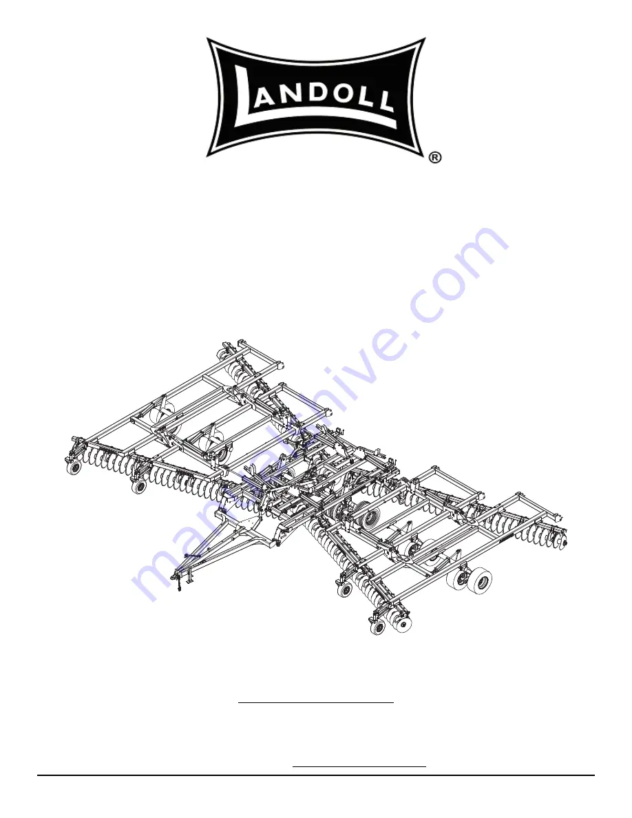
LANDOLL CORPORATION

1900 North Street

Marysville, Kansas 66508

(785) 562-5381

800-428-5655 ~ WWW.LANDOLL.COM

Model 6250 Disc

Operator’s Manual

Summary of Contents for 6250

Page 1: ...F 733 1118 11 2018 Present LANDOLL CORPORATION 1900 North Street Marysville Kansas 66508 785 562 5381 800 428 5655 WWW LANDOLL COM Model 6250 Disc Operator s Manual...

Page 2: ......

Page 3: ...Model Specifications 2 1 General Torque Specifications rev 4 97 2 3 Hydraulic Fitting Torque Specifications 2 4 3 Assembly Instructions Disc Gangs 3 3 Mounting Center Frame Tires and Wheels 3 3 Dual...

Page 4: ...Field Operation 4 7 Leveling Side to Side 4 8 Leveling Front to Rear 4 10 Hitch Adjustment 4 11 Scraper Adjustment 4 12 Coil Tine Harrow 4 13 Operation Adjustment 4 15 Maintenance 4 15 Front Gauge Wh...

Page 5: ...ur equipment before using it and describes adjustments needed Gives practical advice for the care and maintenance of your Landoll equipment Drawings in this section locate adjustment points on the equ...

Page 6: ...ement be sure to clean the surface to remove any dirt or residue Where possible sign placement should protect the sign from abrasion damage or obstruction from mud dirt oil etc DANGER Transporting Saf...

Page 7: ...e the skin causing serious injury Use a piece of cardboard rather than hands to search for suspected leaks 2 Any fluid injected into the skin must be surgically removed within a few hours or gangrene...

Page 8: ...rger chain may be required Chain capacity must be greater then the TOTAL weight of all towed implements 2 A second chain should be used between each implement 3 Attach the chain to the tractor drawbar...

Page 9: ...s Center Frame 320 70R15 Wings 235 75R17 5 Tires W 8 Bolt Walking Dual Wheels Center Frame VF 410 50 R16 5 Wings 235 75R17 5 Tires W 8 Bolt Walking Dual Wheels Center Frame VF 410 50 R16 5 Wings Spind...

Page 10: ...115psi 20 5 X 8 0 10 Load Range D 1 320 lbs 70 psi VF 410 50 R16 5 BKT 153A8 B 8 050 lbs 30 mph 73 psi Specific Bolt Torques Bolts Nuts Torque FT LBS Center Frame Nuts Inner Torque to 100 Ft Lbs whil...

Page 11: ...9 16 12 55 62 80 100 110 137 9 16 18 60 75 90 112 130 162 5 8 11 75 94 110 137 170 212 5 8 18 85 106 130 162 180 225 3 4 10 130 162 200 250 280 350 3 4 16 150 188 220 275 320 400 7 8 9 125 156 320 40...

Page 12: ...on grade 8 capscrews Use value in if using prevailing torque nuts Parker Brand Fittings Dash Size 37 Degree JIC O Ring ORS O Ring Boss ORB 4 11 13 15 17 13 15 5 14 16 21 23 6 20 22 34 36 25 29 8 43 47...

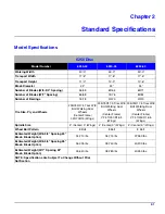
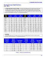
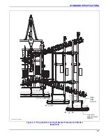
Page 13: ...STANDARD SPECIFICATIONS 2 5 Table provided for general use NOTES...

Page 14: ...2 6 F 733 1118 STANDARD SPECIFICATIONS Figure 2 1 Wing Stabilizer and Light Bracket Placement 40 Model Left Half 26 91 22 91 156 6250 40 placement p1 24 1 2 REEL ARM STOPS YELLOW REFLECTOR DECAL 5 1 2...

Page 15: ...STANDARD SPECIFICATIONS 2 7 Figure 2 2 Wing Stabilizer and Light Bracket Placement 40 Model Right Half 26 91 22 91 156 6250 40 placement p2 24 1 2 REEL ARM STOPS YELLOW REFLECTOR DECAL 5 1 2...

Page 16: ...2 8 F 733 1118 STANDARD SPECIFICATIONS Figure 2 3 Wing Stabilizer and Light Bracket Placement 45 Model Left Half 26 105 23 24 1 2 156 6250 45 placement p1 5 1 2 REEL ARM STOPS YELLOW REFLECTOR DECAL...

Page 17: ...STANDARD SPECIFICATIONS 2 9 Figure 2 4 Wing Stabilizer and Light Bracket Placement 45 Model Right Half 26 105 23 24 1 2 156 6250 45 placement p2 5 1 2 REEL ARM STOPS YELLOW REFLECTOR DECAL...

Page 18: ...2 10 F 733 1118 STANDARD SPECIFICATIONS Figure 2 5 Wing Stabilizer and Light Bracket Placement 50 Model Left Half 22 21 24 1 2 5 1 2 6250 50 placement p1 REEL ARM STOPS YELLOW REFLECTOR DECAL...

Page 19: ...STANDARD SPECIFICATIONS 2 11 Figure 2 6 Wing Stabilizer and Light Bracket Placement 50 Model Right Half 22 21 24 1 2 5 1 2 6250 50 placement p2 REEL ARM STOPS YELLOW REFLECTOR DECAL...

Page 20: ...2 12 F 733 1118 STANDARD SPECIFICATIONS Figure 2 7 Dual Tire Scraper Installation 43 1 2 29 1 2 SEE DETAIL A DETAIL A EXTRA SCRAPER PLATE USED ON OUTER TIRES ONLY dual tire scraper installation...

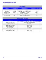
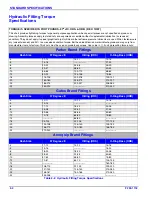
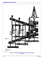
Page 21: ...STANDARD SPECIFICATIONS 2 13 Table provided for general use NOTES...

Page 22: ...2 14 F 733 1118 STANDARD SPECIFICATIONS Figure 2 8 Coil Tine Harrow Placement 40 Model 1 of 2 15 5 10 1 4 5 6250 40 Harrow placement p1 YELLOW REFLECTOR U BOLT MOUNT REAL ARM STOPS...

Page 23: ...STANDARD SPECIFICATIONS 2 15 Figure 2 9 Coil Tine Harrow Placement 40 Model 2 of 2 5 10 1 4 5 6250 40 harrow placement p2 YELLOW REFLECTOR U BOLT MOUNT REAL ARM STOPS...

Page 24: ...2 16 F 733 1118 STANDARD SPECIFICATIONS Figure 2 10 Coil Tine Harrow Placement 45 Model 1 of 2 3 6 6 2 6250 45 harrow placement p1 REEL ARM STOPS YELLOW REFLECTOR U BOLT MOUNT...

Page 25: ...STANDARD SPECIFICATIONS 2 17 Figure 2 11 Coil Tine Harrow Placement 45 Model 2 of 2 6 2 6 6250 45 harrow placement p2 REEL ARM STOPS YELLOW REFLECTOR U BOLT MOUNT...

Page 26: ...2 18 F 733 1118 STANDARD SPECIFICATIONS Figure 2 12 Coil Tine Harrow Placement 50 Model 1 of 2 1 1 2 6250 50 harrow placement p1 6 7 2 7 8 REEL ARM STOPS YELLOW REFLECTOR U BOLT MOUNT...

Page 27: ...STANDARD SPECIFICATIONS 2 19 Figure 2 13 Coil Tine Harrow Placement 50 Model 2 of 2 1 1 2 7 6 6250 50 harrow placement p2 REEL ARM STOPS YELLOW REFLECTOR U BOLT MOUNT...

Page 28: ...Page Intentionally Blank...

Page 29: ...General Torque Specifications rev 4 97 on page 2 3 CAUTION DANGER WARNING DANGER Be sure to bleed the hydraulic system of all air in lines after installation Failure to bleed the system of all air can...

Page 30: ...10 X 5 1 2 HEX HEAD CAP SCREW 3 4 10 X 8 1 2 HEX HEAD CAP SCREW W FLAT WASHER LEFT CENTER REAR DISC GANG ASSEMBLY 3 4 10 X 8 1 2 HEX HEAD CAP SCREW W FLAT WASHER 3 4 10 X 2 1 4 HEX HEAD CAP SCREW CLAM...

Page 31: ...studs being careful not to damage the stud threads Make sure that the disc wheel is flat against the mounting surface There will be a wheel spacer on the hub and it needs to be mounted between the hu...

Page 32: ...ation 5 7 11 5 1 17 5 5 0 7 11 5 1 3 6 5 2 187 7 5 1 66 0 03 3 7 7 11 5 1 5 5 6 66 0 7 11 5 1 5217 6 66 0 6 7 1 3 1 5266 3 1 1 2 66 0 3 6 5 3 6 5 2 187 7 6 5 2 187 2 187 1 67 5 5217 02817 58 5 803 5 1...

Page 33: ...tach using 3 4 10 x 2 and 3 4 10 x 8 1 2 hex head cap screws and hex lock nuts See Figure 3 3 2 Assemble the tire and wheel assemblies to the wing frames The wings use 8 bolt wheels and 3 slip in spin...

Page 34: ...LOCK NUT LEFT OUTER WING DISC GANG ASSEMBLY LEFT OUTER WING DISC GANG ASSEMBLY REAR FRONT SEE DETAIL A DETAIL A 6250 outer gang inst 1 3 4 THRUST WASHER DOUBLE HINGE 1 8 X 6 1 2 HEX HEAD CAP SCREW HI...

Page 35: ...ble the tire and wheel assemblies to the wing frames The wings use 8 bolt wheels and 3 slip in spindles Torque to 85 to 100 ft lbs NOTE All tire wheel assemblies are mounted with the valve stem facing...

Page 36: ...OLDER WING NUT HOSE HOLDER CLAMP 3 8 16 HEX NUT HOSE HOLDER BRACKET 3 8 16 X 3 1 2 ALL THREAD SCREW 1 4 20 HEX LOCK NUT HITCH RING 41 000 LB SAFETY CHAIN 1 4 20 X 1 HEX HEAD CAP SCREW 1 2 13 X 12 HEX...

Page 37: ...flange nut with the flange pointing upward as well Do not tighten this cap screw so the hose holder bracket may pivot freely in this joint 4 Slide the hose holder bracket over the screw and secure wi...

Page 38: ...T 1 1 2 SPLIT LOCK WASHER LEVELER BALL JOINT LINK 1 1 2 6 X 6 HEX HEAD CAP SCREW 90 ELBOW W 1 32 RESTRICTOR LEVELER ASSEMBLY 3 4 10 HEX LOCK NUT LEVELER PIN KEEPER 3 4 10 X 2 1 4 HEX HEAD CAP SCREW 1...

Page 39: ...eveler tube Drawbars of 17 or less could require the 2nd hole in 6 Attach leveler tower to the top of the leveler ball joint link with hitch pin 1 2 x 2 1 4 grooved alloy pin 2 1 1 2 washers and 1 8 h...

Page 40: ...he center lift and secure with a 5 8 11 hex lock nut 3 Insert 90 elbow fitting in the front of the limit valve 4 Using 5 16 18 x 5 hex head cap screws secure the front end of the depth stop tube assem...

Page 41: ...LY 4 1 2 X 16 HYD REPHASE CYLINDER 3 8 X 31 HOSE ASSEMBLY 3 8 X 96 HOSE ASSEMBLY 3 8 X 24 HOSE ASSEMBLY 3 8 X 128 HOSE ASSEMBLY 3 8 X 90 HOSE ASSEMBLY 3 8 X 222 HOSE ASSEMBLY 1 2 X 49 HOSE ASSEMBLY 1...

Page 42: ...136 HOSE ASSEMBLY 3 8 X 123 HOSE ASSEMBLY 3 8 X 54 HOSE ASSEMBLY 3 8 X 42 HOSE ASSEMBLY 3 8 X 24 HOSE ASSEMBLY 3 8 X 90 HOSE ASSEMBLY 3 8 X 10⁵ HOSE ASSEMBLY 3 4 16 MALE COUPLER 3 8 X 276 HOSE ASSEMBL...

Page 43: ...3 8 X 24 HOSE ASSEMBLY 4 1 2 X 16 HYD REPHASE CYLINDER 3 8 X 31 HOSE ASSEMBLY 3 8 X 96 HOSE ASSEMBLY 3 8 X 24 HOSE ASSEMBLY 3 8 X 136 HOSE ASSEMBLY 3 8 X 10⁵ HOSE ASSEMBLY 3 8 X 244 HOSE ASSEMBLY 1 2...

Page 44: ...146 HOSE ASSEMBLY 3 8 X 140 HOSE ASSEMBLY 3 8 X 54 HOSE ASSEMBLY 3 8 X 42 HOSE ASSEMBLY 3 8 X 24 HOSE ASSEMBLY 3 8 X 90 HOSE ASSEMBLY 3 8 X 114 HOSE ASSEMBLY 3 4 16 MALE COUPLER 3 8 X 276 HOSE ASSEMBL...

Page 45: ...3 8 X 24 HOSE ASSEMBLY 4 1 2 X 16 HYD REPHASE CYLINDER 3 8 X 31 HOSE ASSEMBLY 3 8 X 96 HOSE ASSEMBLY 3 8 X 24 HOSE ASSEMBLY 3 8 X 156 HOSE ASSEMBLY 3 8 X 120 HOSE ASSEMBLY 3 8 X 275 HOSE ASSEMBLY 1 2...

Page 46: ...Y 3 8 X 130 HOSE ASSEMBLY 3 4 16 MALE COUPLER 3 8 X 276 HOSE ASSEMBLY 3 8 X 20 HOSE ASSEMBLY 3 8 X 72 HOSE ASSEMBLY 4 1 2 X 30 HYDRAULIC CYLINDER 3 8 X 185 HOSE ASSEMBLY 4 X 30 HYDRAULIC CYLINDER 3 8...

Page 47: ...1 0 1 1 5217 0 1 2 66 0 75 163257 2 5 8 6 7 26 520 0 1 2 26 2 1 72 5 5 2 1 5 1 5 26 66 0 1 5 26 66 0 26 66 0 1 5 5217 2 0 1 5217 2 0 1 7 2 5 675 725 37 5 7 6 9 37 5 75 21 2 2 5 675 725 37 5 7 6 9 37 5...

Page 48: ...ER 40 45 OR 4 1 2 X 30 50 1 1 4N FLAT WASHER 5 16 X 2 1 2 SPRING SLOTTED PINS 40 OR ROLL PINS PROVIDED W CYLINDER 45 50 2 WING FOLD SPACER 1 2 WIDE 1 1 4 X 9 9 16 FOLD PIN WING FOLD ROLLER 1 3 16 WIDE...

Page 49: ...d of the outer wing fold cylinders and install the 4 extra long 90 degree fittings This will allow the hoses to be installed when the cylinder is up next to the wing stabilizers Install the JIC swivel...

Page 50: ...Bracket Mounting Installation 6250 wing stabilizer mounting p1 6250 40 AND 45 MODELS 3 4 10 HEX LOCK NUT OUTER WING STOP WING STABILIZER 3 4 10 X 5 HEX HEAD CAP SCREW 6250 50 MODEL FOLD STABILIZER MOU...

Page 51: ...RESTRICTED OUTER WING FOLD INNER WING FOLD INNER WING FOLD OUTER WING FOLD BLACK FITTING 1 16 RESTRICTED REMOVE ORIGINAL 90 DEGREE FITTING AND INSTALL EXTRA LONG 90 DEGREE FITTING HERE BLACK FITTING...

Page 52: ...EAD CAP SCREW 34 EXTENSION HARNESS 1 4 20 X 3 4 HEX HEAD CAP SCREW RH BRACKET WELDMENT AG FLASHER CONTROL MODULE U BOLT SMV MOUNTING BRACKET 1 4 20 HEX LOCK NUT REAR WARNING LIGHT HARNESS AG RED SINGL...

Page 53: ...ws and hex lock nuts IMPORTANT Make sure lights are positioned for maximum visibility from the rear 6 Install the rear warning light harness to the frame Connect 2 pin and 3 pin ends to each of the wa...

Page 54: ...ion 6250 general harrow assembly HARROW ASSEMBLY GANG BAR MOUNTING PLATE 3 4 10 x 7 GR8 HEX HEAD CAP SCREW 20 1 2 NOTE SIDE PLATE REMOVED FOR CLARITY HARROW ASSEMBLY HARROW ARM ASSEMBLY 3 4 10 PREVAIL...

Page 55: ...arm to upper hole on rear center or wing frame or u bolt mount using 1 8 x 6 1 2 hex head cap screw and hex lock nut 5 Assemble 17 heavy spring assembly to tine arm using 1 pivot pin and 5 16 x 1 1 2...

Page 56: ...X 78 HOSE ASSEMBLY 1 4 X 75 HOSE ASSEMBLY 1 4 X 48 HOSE ASSEMBLY 1 4 X 42 HOSE ASSEMBLY 1 4 X 57 HOSE ASSEMBLY 1 4 X 52 HOSE ASSEMBLY 1 4 X 90 HOSE ASSEMBLY 1 4 X 120 HOSE ASSEMBLY 1 4 X 68 HOSE ASSE...

Page 57: ...HOSE ASSEMBLY 1 4 X 75 HOSE ASSEMBLY 1 4 X 48 HOSE ASSEMBLY 1 4 X 42 HOSE ASSEMBLY 1 4 X 57 HOSE ASSEMBLY 1 4 X 52 HOSE ASSEMBLY 1 4 X 90 HOSE ASSEMBLY 1 4 X 130 HOSE ASSEMBLY 1 4 X 68 HOSE ASSEMBLY 9...

Page 58: ...1 4 X 78 HOSE ASSEMBLY 1 4 X 75 HOSE ASSEMBLY 1 4 X 57 HOSE ASSEMBLY 1 4 X 52 HOSE ASSEMBLY 1 4 X 64 HOSE ASSEMBLY 1 4 X 60 HOSE ASSEMBLY 1 4 X 10² HOSE ASSEMBLY 1 4 X 156 HOSE ASSEMBLY 90 JIC SWIVEL...

Page 59: ...REW 1 8 HEX NUT 17 HEAVY SPRING ASSEMBLY 1 8 HEX LOCK NUT 1 LOCK WASHER ADJUSTMENT PIN SNAP RING 1 X 8 ADJUSTMENT BOLT 1 1 2 FLANGE BEARING 1 1 2 PIVOT BUSHING 5 16 X 1 1 2 SPRING SLOTTED PIN PIVOT PI...

Page 60: ...R STRAIGHT ADAPTER 1 2 13 X 1 1 2 HEX HEAD CAP SCREW 1 2 SPLIT LOCK WASHER 3 4 10 X 6 HEX HEAD CAP SCREW GR8 GANGBAR MOUNT PLATE 1 1 2 FLANGE BEARING 1 1 2 PIVOT BUSHING REEL ARM MACHINERY BUSHING PIV...

Page 61: ...stop and a trunnion stop with 1 2 13 x 2 1 4 hex head cap screws and split lock washer See Figures 3 28 and 3 29 See Figures 2 1 through 2 6 for reel arm stop locations Figure 3 29 Conditioner Reel Ar...

Page 62: ...Finishing Conditioner Reel Installation Hydraulic Hose Placement Left Half Figure 3 32 Finishing Conditioner Reel Installation Hydraulic Hose Placement Right Half BULKHEAD RUN TEE SMALL LOOP 6250 45...

Page 63: ...1 Install hoses per Figures 3 24 through 3 26 Hose routing to follow Figures 3 31 and 3 32 12 Install hose clamp brackets as shown at hinge lines with 1 2 13x1 1 2 round head square neck bolts and nut...

Page 64: ...lement damage Follow instructions for charging the hydraulic fold system as described in Hydraulic Fold System on page 4 5 4 Connect lights to the tractor and verify operation 5 Check tires for proper...

Page 65: ...ipment is idle Failure to take preventive measures against accidental lowering can result in serious personal injury Always lock the tractor drawbar in the center position when transporting the unit F...

Page 66: ...n Disc Preparation Figure 4 1 Disc Scraper to Disc Blade 1 Prior to operating the 6250 Disc inspect it thoroughly for good operating condition 2 Replace worn or missing parts 3 When the machine is new...

Page 67: ...ller wing frame cylinders plumbed in series with larger center frame cylinders It is important that the cylinders be connected in the proper series for the lift system to operate correctly When the cy...

Page 68: ...reservoir to make sure it is within operating limits 3 Always fully extend the cylinders and hold the lever to ensure the cylinders are rephased before starting any field operation This will keep all...

Page 69: ...linders several times The cylinder rod travel should be smooth and positive when all air has been purged from the system Due to large amounts of hydraulic oil required recheck the tractor fluid level...

Page 70: ...n unfolding will result in serious damage to the implement Be sure other people and pets are a safe distance away 2 Fully raise the folded machine to unhook the locks and continue to hold the lever to...

Page 71: ...h of each frame section and to control the leveling feature Maximum discing depth cannot be achieved by raising the lift wheels off the ground Little or no weight on the lift wheels will cause the fra...

Page 72: ...des are 1 off the ground d Measure the distance from the walking beam spindle to the top of the frame on both sides If there is a difference it needs to be adjusted by turning the cylinder rods with t...

Page 73: ...the wing frame measure the distance from the welded washer to the top side of the wing frame See Figure 4 11 f Measure the same distance on the wing frame The wing frames are generally set to the sam...

Page 74: ...rear gangs are too deep If there is a furrow left from the rear gangs the front gangs are too deep 3 Implements with the hydraulic leveler can make adjustments on the go from the tractor A reference...

Page 75: ...nd b Adjust the hydraulic leveler in or out until the pressure is relieved on the leveling system See Leveling Side to Side on page 4 8 and Leveling Front to Rear on page 4 10 c Remove the 1 1 2 6 X 6...

Page 76: ...In wet conditions the scraper may be set against the disc blade and will function as a spring loaded scraper 2 Scraper blades have two positions and are reversible The blades are initially set in the...

Page 77: ...essure CAUTION WARNING The coil tine harrow adds significant amount of weight to the rear of implement and can create negative hitch weight Be careful when unhitching the implement as the implement hi...

Page 78: ...Adjustment and Settings 20 1 2 RECOMMENDED HARROW SETTINGS 6250 harrow settings HARROW GANG BAR PLATE HARROW ADJUSTMENT HOLES 1 2 13 x 1 1 4 RD HEAD SQ NECK SCREW ANGLE ADJUSTMENT PLATE 1 8 HEX NUT H...

Page 79: ...ions A flatter tooth angle will allow the harrow to clear heavier and or wetter residue The tine tooth angle is set for each row by removing the spring clip pin at each tine angle adjustment handle an...

Page 80: ...ORTANT Excessive down pressure can cause the implement to throw a center ridge 3 To adjust the gauge wheel depth loosen and adjust the nuts on each side of the gauge wheel cross See Figure 4 19 A wren...

Page 81: ...teel The chrome boron steel has a higher hardness than traditional carbon steel blades for increased wear Higher hardness makes roll sharpening more difficult often with mixed results and is not cover...

Page 82: ...pth One turn will equal approximately 1 8 adjustment in depth 2 The gauge on the side of the depth stop tube gives a reference for depth setting The A setting refers to maximum operating depth IMPORTA...

Page 83: ...GREASE SEAL INNER BEARING CONE INNER BEARING CUP 8 BOLT HUB OUTER BEARING CUP OUTER BEARING CONE SPINDLE WASHER 1 14 HEX SLOT NUT HUB CAP 2 1 4 SPINDLE 3 16 X 1 1 2 COTTER PIN 6250 wheel bearing main...

Page 84: ...e star washer side 16 Torque outer nut to 300 ft lbs Endplay of 001 to 010 must be present in the adjust wheel bearing assembly 17 Bend over one tab of star washer that is aligned with a flat on the o...

Page 85: ...follow all federal state and local requirements before transporting the Disc 2 The 6250 should be transported only by tractor required for field operation The implement weight should not exceed more t...

Page 86: ...s before transporting Check wheel lug bolts to insure tightness Figure 4 23 Hitch Speed Identification Symbol and Safety Chain 8 Know the transport heights and widths of the unit before transporting A...

Page 87: ...INTS INTERVAL Hours Unless Stated 1 Disc Gang Bearings 1 each 10 2 Conditioner Reel Bearings Not Shown 1 each 10 3 Walking Tandem Hubs 1 each Top 10 4 Wing Wheel Hubs 1 each 50 5 Front Gauge 6 Bolt Wh...

Page 88: ...will let grease pass and not harm the seal Regular lubrication will maintain a full grease cavity and help purge any contaminants Grease the bearings before long periods of storage to prevent moisture...

Page 89: ...Apply a light coating of oil or grease to exposed cylinder rods to prevent them from rusting f Lubricate each point of the machine as stated in Lubrication Maintenance on page 4 24 2 Store the unit i...

Page 90: ...NOTES...

Page 91: ...tch adjustment too high Lower implement hitch point Gauge wheels too high allowing wings to go to deep Properly reset gauge wheels UNEVEN DEPTH Frame not level side to side Level center frame side to...

Page 92: ...lve not working Repair valve HYDRAULIC UNIT SETTLING ONE WING RAISING Center frame cylinder leaking internally on side of unit that wing is raising Repair center master cylinder HYDRAULIC WING SETTLIN...

Page 93: ...ontrol Revision Log Date Revision End Item Improvement s Description and Comments 01 26 14 F 733 6250 Initial Release 11 05 18 F 733 1118 6250 ECN44101 Galaxy Tire Wheel revision wheel hub lubrication...

Page 94: ...ring facilities Model 6250 Disc Operator s Manual Re Order Part Number F 733 1118 LANDOLL CORPORATION 1900 North Street Marysville Kansas 66508 785 562 5381 800 428 5655 WWW LANDOLL COM Copyright 2010...

Reviews: