background image

ICS-P570 User Manual 


ICS-P570 User Manual


Version: 1.0 

Date of Release:2023-04-21 

Industrial Communication Platforms


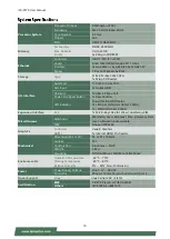
Summary of Contents for ICS-P570

Page 1: ...ICS P570 User Manual ICS P570 User Manual Version 1 0 Date of Release 2023 04 21 Industrial Communication Platforms ...

Page 2: ...re is something you should pay special attention to while using the product This mark indicates that there is a caution or warning and it is something that could damage your property or product To obtain additional documentation resources and software updates for your system please visit the Lanner Download Center As certain categories of documents are only available to users who are logged in ple...

Page 3: ...ad Huilongguan Town Changping District Beijing 102208 China T 86 010 82795600 F 86 010 62963250 E service ls china com cn USA Lanner Electronics Inc 47790 Westinghouse Drive Fremont CA 94539 T 1 855 852 6637 F 1 510 979 0689 E sales_us lannerinc com Canada Lanner Electronics Canada Ltd 3160A Orlando Drive Mississauga ON L4V 1R5 Canada T 1 877 813 2132 F 1 905 362 2369 E sales_ca lannerinc com Euro...

Page 4: ...rference to radio communications However there is no guarantee that interference will not occur in a particular installation If this equipment does cause harmful interference to radio or television reception which can be determined by turning the equipment off and on the user is encouraged to try to correct the interference by one or more of the following measures Reorient or relocate the receivin...

Page 5: ...allation only by a skilled person who knows all Installation and Device Specifications which are to be applied Do not carry the handle of power supplies when moving to another place Please conform to your local laws and regulations regarding safe disposal of lithium BATTERY Disposal of a battery into fire or a hot oven or mechanically crushing or cutting of a battery can result in an explosion Lea...

Page 6: ...amount of airflow required for safe operation of the equipment is not compromised To avoid a hazardous load condition be sure the mechanical loading is even when mounting Consideration should be given to the connection of the equipment to the supply circuit and the effect that overloading of the circuits might have on over current protection and supply wiring Appropriate consideration of equipment...

Page 7: ...ontre les effets néfastes du bruit externe et réduire les risques d électrocution en cas de foudre Pour désinstaller l équipement débranchez le câble de mise à la terre après avoir éteint l appareil Un câble de mise à la terre est requis et la zone reliant les sections du conducteur doit faire plus de 4 mm2 ou 10 AWG Loosen the screw of the earthing point Connect the grounding cable to the ground ...

Page 8: ...ation 13 Opening the Chassis 21 Installing the System Memory 23 Installing the SATA Storage Optional 24 Installing the LTE Module Optional 25 Installing SIM Cards SD Cards Optional 28 DIN Rail Mounting Optional 29 Main Page 33 Advanced Page 34 Chipset 52 Security 55 Boot Menu 58 Save and Exit Menu 59 RMA Service Request Form 63 ...

Page 9: ...e USB 3 0 and 2x DIO Ports Optional LTE module support Dual 12 48Vdc Power Input Wide Operating Temperature 40 70 C Your package contains the following items 1x ICS P570 Network Security Platform 1x Console Cable 1x Wall mount Kit mSATA kit w thermal pad screws sink SKU No Main Features ICS P570A AMD V1404I support 2x DRAM channels 6x Intel i210 IT GbE LAN with 1 pair bypass 1x M 2 for SATA Storag...

Page 10: ... Power Status HDD Status 2x LEDs per LAN ports total 12 LEDs 1x LED DI DO total 4 LEDs Expansion Interface M 2 1x M 2 B Key 3042 for LTE w dual Nano SIM Miscellaneous Watchdog Watchdog timer 256 level time interval system reset software programmable TPM Onboard TPM 2 0 Graphics Controller Vega 8 Graphics HDMI 1x Internal HDMI Pin header Mechanical Dimension W x H x D 65 x 201 x 196mm Fanless Yes C...

Page 11: ...x 6 pin Terminal Block for dual DC input 12 48V F4 LED Indicators F5 Antenna 2x Antennas F6 USB Port 1x USB 3 0 Port F7 Console Port 1x RJ45 Console Port F8 LAN SFP Port SKU A 6x GbE RJ45 Ports SKU B 4x GbE RJ45 Ports 2x SFP Ports F9 DIO 4x2 pin Terminal block for 2x DI 2x DO F4 F5 F6 F7 F8 F9 Power Status HDD Status 3 LEDs LAN Ports 12 LEDs DI DO 4 LEDs F1 F2 F3 ...

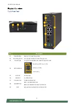
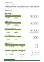
Page 12: ...ICS P570 User Manual 12 No Description B1 SD SIM Cover SD Card Dual Nano SIM Card Cover B1 ...

Page 13: ...ICS P570 User Manual 13 ...

Page 14: ...J10 LPC1114 Burn Select Jumper Description 1 2 Default Normal 2 3 Burn Mode 2 JCMOS1 Clear CMOS Jumper Description 1 2 Default Normal 2 3 Clear CMOS RAM 3 SEL1 Hardware Software Select Jumper Description 1 2 Software Reset 2 3 Default Hardware Reset 4 PWR1 Power On Off Jumper Description 1 2 Power On Off 2 3 Default Normal 1 BAT1 Battery Connector Pin No Description Pin No Description 1 VDD_3 3V_B...

Page 15: ...A18 GND B2 P12V B18 GND A3 P12V A19 P1_RT_1 B3 P12V B19 PCIE_TXP5_EXP A4 GND A20 GND B4 GND B20 PCIE_TXN5_EXP A5 NC A21 PCIE_RXP5_EXP B5 CPU_SCL1 B21 GND A6 NC A22 PCIE_RXN5_EXP B6 CPU_SDA1 B22 GND A7 AGPIO89 A23 GND B7 GND B23 PCIE_TXP6_EXP A8 AGPIO90 A24 GND B8 P3V3 B24 PCIE_TXN6_EXP A9 P3V3 A25 PCIE_RXP6_EXP B9 NC B25 GND A10 P3V3 A26 PCIE_RXN6_EXP B10 P3V3_SB B26 GND A11 FP5_PCIE_RST1 A27 GND ...

Page 16: ... HDMI_DATA1_DN 16 HDMI_DDC_SDA 7 HDMI_DATA0_DP 17 GND 8 GND 18 V5S_DS 9 HDMI_DATA0_DN 19 HDMI_CBL_HPD 10 HDMI_CLK_DP 8 NGFF1 M 2 M Key Connector Pin No Description Pin No Description Pin No Description Pin No Description 1 GND 39 GND 2 P3V3 40 M2_SCL 3 GND 41 SATA_RX0_P 4 P3V3 42 M2_SDA 5 NC 43 SATA_RX0_N 6 NC 44 NC 7 NC 45 GND 8 NC 46 NC 9 GND 47 SATA_TX0_N 10 M2_ACT_LED_L 48 NC 11 NC 49 SATA_TX0...

Page 17: ...43 NC 6 M2_PWROFF_N 44 UIM2_CLK 7 USB02_L_P 45 GND 8 M2_WDIS1_N 46 UIM2_RST 9 USB02_L_N 47 NC 10 M 2_LED_N 48 UIM2_PWR 11 GND 49 NC 12 NC 50 NC 13 NC 51 GND 14 NC 52 NC 15 NC 53 NC 16 NC 54 NC 17 NC 55 NC 18 NC 56 NC 19 NC 57 GND 20 NC 58 NC 21 NC 59 NC 22 NC 60 NC 23 WAKE_ON_WAN 61 NC 24 NC 62 NC 25 LTE_DPR 63 NC 26 M2_WDIS2_N 64 NC 27 GND 65 NC 28 NC 66 UIM1_DET 29 USB03_RX_N 67 M2B_RESET_N 30 U...

Page 18: ... LAN 1 2 Connector Pin No Description Pin No Description A1 RJ1_DXP0 B1 RJ2_DXP0 A2 RJ1_DXN0 B2 RJ2_DXN0 A3 RJ1_DXP1 B3 RJ2_DXP1 A4 RJ1_DXP2 B4 RJ2_DXP2 A5 RJ1_DXN2 B5 RJ2_DXN2 A6 RJ1_DXN1 B6 RJ2_DXN1 A7 RJ1_DXP3 B7 RJ2_DXP3 A8 RJ1_DXN3 B8 RJ2_DXN3 13 LAN2 LAN 3 4 Connector Pin No Description Pin No Description A1 LAN3_MDI0P B1 LAN4_MDI0P A2 LAN3_MDI0N B2 LAN4_MDI0N A3 LAN3_MDI1P B3 LAN4_MDI1P A4 ...

Page 19: ...5 CT 10 LAN6_MDI3N 16 FIBER5 LAN 5 Connector Pin No Description Pin No Description 1 GND 11 GND 2 SFP5_TX_FAULT 12 SFP5_RD_N 3 SFP5_TX_DIS 13 SFP5_RD_P 4 SFP5_I2C_SDA 14 GND 5 SFP5_I2C_SCL 15 P3V3_SFP5_R 6 SFP5_MOD_ABS 16 P3V3_SFP5_T 7 GND 17 GND 8 SFP5_RX_LOS 18 SFP5_TD_P 9 GND 19 SFP5_TD_N 10 GND 20 GND 17 FIBER6 LAN 6 Connector Pin No Description Pin No Description 1 GND 11 GND 2 SFP6_TX_FAULT ...

Page 20: ...CS P570 User Manual 20 9 GND 19 SFP6_TD_N 10 GND 20 GND 18 DIO1 Digital Input Output Connector Pin No Description Pin No Description 1 DO_1_T 5 s 2 ISO_GND 6 ISO_GND 3 DO_2_T 7 DI_2_T 4 ISO_GND 8 ISO_GND ...

Page 21: ...ompletely Also please wear ESD protection gloves when conducting the steps in this chapter 1 Power off the system and unplug the power cord 2 Unscrew the five 5 screws on the system s top panel Then remove the side metal partition 3 Turn the system upside down Unscrew the seven 7 screws on the system s rear and top bottom panels Rear Panel Top Panel Bottom Panel ...

Page 22: ...ICS P570 User Manual 22 4 Lift the cover to remove ...

Page 23: ...cket on the motherboard 3 Align the notches of the DIMM module with the socket key in the pin slot 4 Insert the module into the slot at a diagonal angle and press down until it is firmly seated by the clips on both sides 5 Repeat the steps to insert a second DIMM module 6 Next thermal pad placement Remove the protective film on the two 2 Thermal Pad included in accessory pack and gently place on t...

Page 24: ...gn the notch of the SATA storage card with the socket key in the pin slot 4 Insert the storage card pins at 30 degrees into the socket until it is fully seated 5 Push down on the module card and secure it with one 1 screws 6 Next thermal pad placement Remove the protective film on the thermal pad included in the accessory pack and gently place on the module card 7 Then place the metal partition ov...

Page 25: ...nas Please follow the procedures for installation 1 Locate the M 2 slot on the motherboard 2 Align the notch of the module card with the socket key in the pin slot 3 Insert the module card at 30 degrees into the socket until it is fully seated 4 Push down on the module card and secure it with a screw Notch Socket Key ...

Page 26: ...n the accessory pack and gently place on the bottom chassis cover Front Panel 1 Locate the two 2 antenna hole placement A1 A2 Locate the two 2 IPEX connectors on the LTE module card 2 Connect the RF cables to the IPEX connectors on the LTE module card and screw the other end of the cables in the antenna holes A2 ㄉ A1 A1 A2 ㄉ ...

Page 27: ...ICS P570 User Manual 27 3 Screw the two 2 antennas to the system ...

Page 28: ...ard slot is located on the bottom panel Remove the side metal partition on the bottom panel by unscrewing the two screws 2 Locate the SD card and dual Nano SIM card slots Insert and push the SD card or Nano SIM card all the way in until it clicks into place For Nano SIM the gold contacts facing downwards Repeat if dual SIM cards will be placed 3 To remove replace the SD SIM card use your fingertip...

Page 29: ... to the rear of the system with three 3 screws 2 Hang the system onto a rail by engaging the hook of the Bracket into the DIN Rail until it is totally fixed Note After the unit is mounted make sure to check that the installation provides strong and appropriate support and that each part is assembled correctly 6 32 L6mm 3 5mmx6mm ...

Page 30: ... wall mount brackets onto the system with two 2 screws on each side 2 On the wall measure the exact place where you want to hang the system and drill four holes that match the four mounting holes on both brackets NOTE the demonstrated screw type can fit in general drywall or shelves Please identify the wall type and select a suitable fixing approach to fix this system to the wall and consult quali...

Page 31: ...sion anchor bolts into the holes and then insert the long screws into the wall screws 4 Align the system s wall bracket holes and engage the four screws in the bracket holes and push the system downwards to lock the screws into position Locked ...

Page 32: ...TE The screenshots presented in this section are for reference only Control Keys Description select a setup screen select an item option on a setup screen Enter select an item option or enter a sub menu adjust values for the selected setup item option F1 display General Help screen F2 retrieve previous values such as the last configured parameters during the last time you entered BIOS F3 load opti...

Page 33: ...rnel version CRB code base X64 Compliancy UEFI version PI version Project Version BIOS release version Build Date and Time MM DD YYYY Access Level Administrator User System Date To set the Date use Tab to switch between Date elements Default range of Year 2005 2099 Default range of Month 1 12 Days dependent on Month System Time To set the Date use Tab to switch between Date elements ...

Page 34: ...ICS P570 User Manual 34 Select the Advanced menu item from the BIOS setup screen to enter the Advanced setup screen Users can select any of the items in the left frame of the screen ...

Page 35: ... Options Description Security Device Support Enabled Disabled Enables or disables BIOS support for security device By disabling this function OS will not show Security Device TCG EFI protocol and INT1A interface will not be available ...

Page 36: ...CR Bank Pending operation None TPM Clear Schedules an Operation for the Security Device NOTE Your computer will reboot during restart in order to change State of Security Device Platform Hierarchy Enabled Disabled Enables or disables Platform Hierarchy Storage Hierarchy Enabled Disabled Enables or disables Storage Hierarchy Endorsement Hierarchy Enabled Disabled Enables or disables Endorsement Hie...

Page 37: ...t not support 1 3 TPM 20 InterfaceType TIS Select TPM 20 Device for the Communication Interface Device Select TPM 1 2 TPM 2 0 Auto TPM 1 2 will restrict support to TPM 1 2 devices while TPM 2 0 will restrict support to TPM 2 0 devices Auto will support both with the default set to TPM 2 0 devices If not found TPM 1 2 devices will be enumerated ...

Page 38: ...ICS P570 User Manual 38 ...

Page 39: ...ICS P570 User Manual 39 ...

Page 40: ...ICS P570 User Manual 40 ...

Page 41: ...ICS P570 User Manual 41 Feature Options Description Control PXE Boot from Disabled Lan1 Lan2 Control PXE Boot from which Lan ...

Page 42: ...ICS P570 User Manual 42 Feature Options Description Console Redirection Enabled Disabled Enables or disables Console Redirection ...

Page 43: ...Extended ASCII char set Bits per second 9600 19200 38400 57600 115200 Selects serial port transmission speed The speed must be matched on the other side Long or noisy lines may require lower speeds Data Bits 7 8 Data Bits Parity None Even Odd Mark Space A parity bit can be sent with the data bits to detect some transmission errors Stop Bits 1 2 Indicates the end of a serial data packet Flow Contro...

Page 44: ...port for ANSI VT100 terminals Recorder Mode Disabled Enabled With this mode enabled only text will be sent This is to capture Terminal data Resolution 100x31 Disabled Enabled Enables or disables extended terminal resolution Putty KeyPad VT100 LINUX XTERM86 SCO ESCN VT400 Selects FunctionKey and KeyPad on Putty ...

Page 45: ...ICS P570 User Manual 45 ...

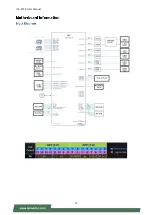
Page 46: ...ICS P570 User Manual 46 Node 0 Information ...

Page 47: ...oded in Above 4G Address Space Only if System Supports 64 bit PCI Decoding SR IOV Support Disabled Enabled If system has SR IOV capable PCIe Devices this option Enables or Disables Single Root IO Virtualization Support BME DMA Mitigation Disabled Enabled Re enable Bus Master Attribute disabled during Pci enumeration for PCI Bridges after SMM Locke ...

Page 48: ...d off support The XHCI ownership change should be claimed by XHCI driver USB Mass Storage Driver Support Enabled Disabled Enables or disables USB Mass Storage Driver Support Port 60 64 Emulation Enabled Disabled Enables I O port 60h 64h emulation support This should be enabled for the complete USB keyboard legacy support for non USB aware OSes USB transfer time out 1 sec 5 sec 10 sec 20 sec The ti...

Page 49: ...sec Device power up delay Auto Manual Maximum time the device will take before it properly reports itself to the Host Controller Auto uses default value for a Root port it is 100 ms for a Hub port the delay is taken from Hub descriptor ...

Page 50: ...d Enables Ipv4 HTTP Boot Support If IPV4 is disabled HTTP boot option will not be created Ipv6 PXE Support Disabled Enabled Enables Ipv6 PXE Boot Support If IPV6 is disabled PXE boot option will not be created Ipv6 HTTP Support Disabled Enabled Enables Ipv6 HTTP Boot Support If IPV6 is disabled HTTP boot option will not be created PXE boot wait time 0 Wait time to press ESC key to abort the PXE bo...

Page 51: ...ntrols the execution of UEFI and Legacy PXE OpROM Storage Do Not Launch UEFI Legacy Controls the execution of UEFI and Legacy Storage OpROM Video Do Not Launch UEFI Legacy Controls the execution of UEFI and Legacy Video OpROM Other PCI device Do Not Launch UEFI Legacy Determines OpROM execution policy for devices other than Network Storage or Video ...

Page 52: ...ICS P570 User Manual 52 Select the Chipset menu item from the BIOS setup screen to enter the Chipset setup screen Users can select any of the items in the left frame of the screen ...

Page 53: ...ICS P570 User Manual 53 ...

Page 54: ...ICS P570 User Manual 54 ...

Page 55: ...left frame of the screen Feature Description Administrator Password If ONLY the Administrator s password is set it only limits access to Setup and is only asked for when entering Setup User Password If ONLY the User s password is set it serves as a power on password and must be entered to boot or enter Setup In Setup the User will have Administrator rights ...

Page 56: ...ed when Platform Key PK is enrolled System mode is User Deployed and CSM function is disabled Secure Boot Customization Standard Customized Secure Boot Mode Custom Standard Set UEFI Secure Boot Mode to STANDARD mode or CUSTOM mode this change is effect after save And after reset the mode will return to STANDARD mode ...

Page 57: ...lows User to provision factory default Secure Boot keys when System is in Setup Mode Install Factory Default keys None Forces System to User Mode install all Factory Default keys Enroll Efi Image None Allows the image to run in Secure Boot mode Enroll SHA256 hash of the binary into Authorized Signature Database db ...

Page 58: ...pt Timeout 1 The Number of seconds to wait for setup activation key 65535 means indefinite waiting BootupNumLock State On Off Select the keyboard NumLock state Quiet Boot Enabled Disable Enables or disables Quiet Boot option Boot mode select LEGACY UEFI DUAL Select boot mode for LEGACY or UEFI Choose boot priority from boot option group Choose specifies boot device priority sequence from available...

Page 59: ...m configuration The following window will appear after the Discard Changes and Exit option is selected Select Yes to Discard changes and Exit Setup Save Changes and Reset When Users have completed the system configuration changes select this option to save the changes and reset from BIOS Setup in order for the new system configuration parameters to take effect The following window will appear afte...

Page 60: ...0 User Manual 60 Restore Defaults Restore default values for all setup options Select Yes to load Optimized defaults Note The items listed under Boot Override will depend on the devices connected to this system ...

Page 61: ...Amber OFF LAN Port 12 LEDs Speed Amber Active ACT Green Amber LINK 10M Flash Data Access OFF 100M Flash Data Access ON Green 1G Flash Data Access ON Amber DI DO 4 LEDs LED Color on Board DI Amber OFF DO Amber OFF HDD Status Power ACT1 LINK1 ACT2 LINK2 ACT3 LINK3 ACT4 LINK4 ACT5 LINK5 ACT6 LINK6 DI1 DI2 DO1DO2 ...

Page 62: ...pense 5 The following conditions are excluded from this warranty Improper or inadequate maintenance by the customer Unauthorized modification misuse or reversed engineering of the product Operation outside of the environmental specifications for the product 1 To obtain an RMA number fill out and fax the RMA Request Form to your supplier 2 The customer is required to fill out the problem code as li...

Page 63: ...IIOT I330 User Manual 63 When requesting RMA service please fill out the following form Without this form enclosed your RMA cannot be processed ...

Reviews: