background image


LEC-7233 


User Manual


Industrial Communication Platforms


Version: 1.6 

Date of Release:2021-09-02 

Summary of Contents for LEC-7233 Series

Page 1: ...LEC 7233 User Manual Industrial Communication Platforms Version 1 6 Date of Release 2021 09 02...

Page 2: ...pes and icons in order to make selected text more transparent and explicable to users Please note that this document contains the following conventions Example Convention Usage iptables F Monospace sh...

Page 3: ...to our technical support department This document is copyrighted 2021 by Lanner Electronics Inc All rights are reserved The original manufacturer reserves the right to make improvements to the produc...

Page 4: ...LOFT 9 Layer No 9 Huinan Road Huilongguan Town Changping District Beijing 102208 China T 86 010 82795600 F 86 010 62963250 E service ls china com cn Lanner Electronics Inc 47790 Westinghouse Drive Fr...

Page 5: ...t the interference by one or more of the following measures Reorient or relocate the receiving antenna Increase the separation between the equipment and receiver Connect the equipment into an outlet o...

Page 6: ...ectuez aucune action qui pourrait cr er un danger pour d autres ou rendre l quipement dangereux Coupez compl tement l alimentation en teignant l alimentation et en d branchant le cordon d alimentation...

Page 7: ...ow of cooling air from internal components Electrostatic discharge ESD can damage equipment and impair electrical circuitry ESD damage occurs when electronic components are improperly handled and can...

Page 8: ...ack should consider the ventilation of the system s intake for taking chilled air and exhaust for emitting hot air openings so that the amount of air flow required for safe operation of the equipment...

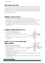
Page 9: ...installer l quipement d branchez le c ble de mise la terre apr s avoir teint l appareil Un c ble de mise la terre est requis et la zone reliant les sections du conducteur doit faire plus de 4 mm2 ou 1...

Page 10: ...install dans des salles de mat riel de traitement de l information conform ment l article 645 du National Electrical Code et la NFPA 75 The machine can only be used in a restricted access location an...

Page 11: ...2 System Specifications 13 Physical Overview 14 Opening the Chassis 24 Installing SO DIMM Memory 25 Installing mSATA and Mini PCIe Module 26 BIOS Setup 27 Main Page 28 Advanced Page 29 Chipset 41 Secu...

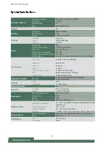
Page 12: ...2 x COM ports and 1 x HDMI port As an industrial gateway the system provides internal TPM for security purpose Intel Celeron N2807 1x DDR3L SO DIMM socket up to 4GB USB 2x USB 2 0 Type A ports and 1x...

Page 13: ...Power On Reset Button 1x Power On Off 1x Reset LED Power Storage Access 3G Status Antenna Hole 2x SMA Antenna Holes Expansion Interface Mini PCIe 1x Full sized Socket with SIM Card Reader 1x Half siz...

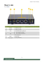
Page 14: ...0 Type A port F2 USB 2 0 2 x USB2 0 Type A ports F3 LAN 3 x 10 100 1000 mbps RJ 45 LAN ports F4 LEDs Green power on off status Green wireless network status Yellow storage access F5 Reset 1 x Reset b...

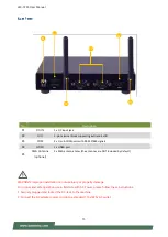
Page 15: ...ly plugged and locked the DC Jack to the machine 2 Connect the AC adapter power cord into a standard 110v 220v AC outlet No Description R1 DC IN 1 x DC input jack R2 DIO 5 pin terminal block supportin...

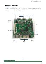
Page 16: ...s the connectors and jumpers on the board Refer to the following picture as a reference of the pin assignments and the internal connectors DC JACK1 HDMI1 COM1 2 JSP1 DIO1 MPE1 RST1 JCMOS1 JLPC1 JTPM1...

Page 17: ...High Definition Multimedia Interface connector Pin Description Pin Description 1 DATA2 2 GND 3 DATA2 4 DATA1 5 GND 6 DATA1 7 DATA0 8 GND 9 DATA0 10 CLK 11 GND 12 CLK 13 N C 14 N C 15 DDC CLK 16 DDC D...

Page 18: ...GND 11 D2DAT 12 D2CLK LAN1 2 3 LAN Connector RJ 45 connector with LED USB1 USB3 0 Type A Connector Pin Description 1 TXD MD0 2 TXD MD0 3 RXD MD1 4 T45 MD2 5 T45 MD2 6 RXD MD1 7 T78 MD3 8 T78 MD3 9 10...

Page 19: ...DO_0 3 DI_1 4 DO_1 5 DI_2 6 DO_2 7 DI_3 8 DO_3 9 V5S 10 GND COM1 COM2 2x DB9 Serial COM ports with RS 232 422 485 Pin Signal Pin Signal 1 Data Carrier Detect DCDA 2 Received Data RXDA 3 Transmit Data...

Page 20: ...purpose Pin Description Pin Description 1 LPC_CLK 2 LAD1 3 PLTRST 4 LAD0 5 LFRAME 6 3 3V 7 LAD3 8 GND 9 LAD2 10 GND MPCIE1 mini PCIe Slot w SIM Full Size Pin Description Pin Description 1 WAKE 2 3 3v...

Page 21: ...ription 1 NC 2 3 3V 3 NC 4 GND 5 NC 6 1 5V 7 NC 8 PWR_UIM1 9 GND 10 DAT_UIM1 11 NC 12 CLK_UIM1 13 NC 14 RST_UIM1 15 GND 16 VPP_UIM1 KEY 17 NC 18 GND 19 NC 20 NC 21 GND 22 PERST 23 NC 24 3 3V 25 NC 26...

Page 22: ...GND 16 N C KEY 17 N C 18 GND 19 N C 20 N C 21 GND 22 N C 23 SATA_RXp 24 3 3V 25 SATA_RXn 26 GND 27 GND 28 N C 29 GND 30 N C 31 SATA_TXn 32 N C 33 SATA_TXp 34 GND 35 GND 36 N C 37 GND 38 N C 39 3 3V 4...

Page 23: ...2 Normal Default 2 3 Clear CMOS J_RST1 2 pin reset pin header Pin Description 1 Ground 2 Reset SPI1 SPIROM pin header for debug purpose Pin Description Pin Description 1 SPI_HOLD 2 N C 3 SPI_CS 4 SPI_...

Page 24: ...when conducting the steps in this chapter To access some components and perform certain service procedures you must perform the following procedures first 1 Power off LEC 7233 and remove power cord 2...

Page 25: ...o 4GB DDR3L 1333MHz Please follow the steps below for proper installations 1 Locate the SO DIMM socket on the motherboard 2 Align the memory module s key with the SO DIMM socket s key 3 Insert the SO...

Page 26: ...he mSATA and the mini PCIe socket the system includes one mSATA MSATA1 one half sized mini PCIe MPE1 and one full sized mini PCIe MPE3 sockets The system will detect no mSATA or mini PCIe card if put...

Page 27: ...elect a setup screen for instance Main Advanced Chipset Security Boot and Save Exit select an item option on a setup screen Enter select an item option or enter a sub menu to adjust values for the sel...

Page 28: ...BIOS Information BIOS Vendor American Megatrends Core Version AMI Kernel version Compliancy UEFI version PI version Project Version BIOS release version System Date To set the Date use Tab to switch...

Page 29: ...LEC 7233 User Manual 29 Select the Advanced menu item from the BIOS setup screen to enter the Advanced setup screen Users can select any of the items in the left frame of the screen...

Page 30: ...device O S will not show Security Device TCG EFI protocol and INT1A interface will not be available Device Select TPM 1 2 TPM 2 0 Auto TPM 1 2 will restrict support to TPM 1 2 devices TPM 2 0 restric...

Page 31: ...LEC 7233 User Manual 31...

Page 32: ...ARE SETUP 32 Feature Options Description Serial Port Disabled Enabled Enable or Disable Serial Port COM Device Settings NA IO 3F8h IRQ 4 COM1 MODE Loopback RS 232 RS 485 RS 422 Select Com Mode as RS 2...

Page 33: ...Manual 33 Feature Options Description Serial Port Disabled Enabled Enable or Disable Serial Port COM Device Settings NA IO 3F8h IRQ 4 COM2 MODE Loopback RS 232 RS 485 RS 422 Select Com Mode as RS 232...

Page 34: ...indows XP SP2 SuSE Linux 9 2 RedHat Enterprise 3 Update 3 Intel Virtualization Technology Disabled Enabled When enabled a VMM can utilize the additional hardware capabilities provided by Vanderpool Te...

Page 35: ...LEC 7233 User Manual 35...

Page 36: ...CORE This value reports the CPU VCORE VGFX This value reports the VGFX VCC5V This value reports the VCC5V Input voltage VCC12V This value reports the VCC12V Input voltage VCC3V This value reports the...

Page 37: ...peed Support Gen1 or Gen2 SATA Mode IDE Mode AHCI Mode Select IDE AHCI Serial ATA Port 0 Enabled Disabled Enable Disable Serial ATA Port 0 STAT Port0 HotPlug Enabled Disabled Enable Disable SATA Port1...

Page 38: ...Current Set display mode for Option ROM Boot option filter UEFI and Legacy Legacy only UEFI only This option controls Legacy UEFI ROMs priority Network Do not launch UEFI Legacy Controls the executio...

Page 39: ...ver EHCI Hand off Disabled Enabled This is a workaround for OSes without EHCI hand off support The EHCI ownership change should be claimed by EHCI driver USB Mass Storage Driver Support Disabled Enabl...

Page 40: ...Chapter 3 SOFTWARE SETUP 40 Feature Options Description PXE Function Disabled LAN1 LAN2 LAN3 Select On Board LAN for enable PXE boot function...

Page 41: ...LEC 7233 User Manual 41 Select the Chipset menu item from the BIOS setup screen to enter the Chipset setup screen Users can select any of the items in the left frame of the screen...

Page 42: ...Chapter 3 SOFTWARE SETUP 42 Feature Options Description Max TOLUD 2 GB 2 25 GB 2 5 GB 2 75 GB 3 GB Maximum Value of TOLUD...

Page 43: ...ture Options Description High Precision Enabled Disabled Enable or Disable the High Precision Event Timer Restore AC Power Loss Power Off Power On Last State Select AC power state when power is re app...

Page 44: ...ntrol the USB EHCI USB 2 0 functions One EHCI controller must always be enabled USB Port 0 Enabled Disabled Enable Disable USB Port 0 USB Port 1 Enabled Disabled Enable Disable USB Port 1 USB Port 2 E...

Page 45: ...frame of the screen Feature Description Administrator Password If ONLY the Administrator s password is set then this only limit access to Setup and is only asked for when entering Setup User Password...

Page 46: ...ure Options Description Setup Prompt Timeout 5 Number of seconds to wait for setup activation key 65535 0xFFFF means indefinite waiting Bootup NumLock State On Off Select the keyboard NumLock state Qu...

Page 47: ...ft frame of the screen Save Changes and Reset When Users have completed the system configuration changes select this option to save the changes and reset from BIOS Setup in order for the new system co...

Page 48: ...card Changes and Exit option is selected Select Yes to Discard changes and Exit Setup Restore Defaults Restore default values for all setup options Select Yes to load Optimized defaults Reset System w...

Page 49: ...al value to zero The software selects the counter s initial value and periodically restarts it Should the counter reach zero before the software restarts it the software is presumed to be malfunctioni...

Page 50: ...s expense 5 The following conditions are excluded from this warranty Improper or inadequate maintenance by the customer Unauthorized modification misuse or reversed engineering of the product Operatio...

Page 51: ...LEC 7233 User Manual 51 When requesting RMA service please fill out the following form Without this form enclosed your RMA cannot be processed...

Reviews: