background image

NCA-1526 User Manual


NCA-1526


User Manual


Version: 1.0 

Date of Release: 2023-06-14 

Network Appliance Platforms


Hardware Platforms for Network Computing


Summary of Contents for NCA-1526

Page 1: ...NCA 1526 User Manual 1 NCA 1526 User Manual Version 1 0 Date of Release 2023 06 14 Network Appliance Platforms Hardware Platforms for Network Computing ...

Page 2: ... please visit the Lanner Download Center As certain categories of documents are only available to users who are logged in please be registered for a Lanner Account at http www lannerinc com to access published documents and downloadable resources In addition to contacting your distributor or sales representative if there are any technical queries you could submit a support ticket to our Lanner Tec...

Page 3: ...ad Huilongguan Town Changping District Beijing 102208 China T 86 010 82795600 F 86 010 62963250 E service ls china com cn USA Lanner Electronics Inc 47790 Westinghouse Drive Fremont CA 94539 T 1 855 852 6637 F 1 510 979 0689 E sales_us lannerinc com Canada Lanner Electronics Canada Ltd 3160A Orlando Drive Mississauga ON L4V 1R5 Canada T 1 877 813 2132 F 1 905 362 2369 E sales_ca lannerinc com Euro...

Page 4: ... void the user s authority to operate this equipment This transmitter must not be co located or operating in conjunction with any other antenna or transmitter Follow these guidelines to ensure general safety Keep the chassis area clear and dust free during and after installation Do not wear loose clothing or jewelry that could get caught in the chassis Fasten your tie or scarf and roll up your sle...

Page 5: ...tuée par un électricien formé ou une personne formée à l électricité connaissant toutes les spécifications d installation et d appareil du produit Ne transportez pas l unité en la tenant par le câble d alimentation lorsque vous déplacez l appareil Electrical equipment generates heat Ambient air temperature may not be adequate to cool equipment to acceptable operating temperatures without adequate ...

Page 6: ...ng of the circuits might have on overcurrent protection and supply wiring Appropriate consideration of equipment nameplate ratings should be used when addressing this concern Reliable Grounding Reliable grounding of rack mounted equipment should be maintained Particular attention should be given to supply connections other than direct connections to the branch circuit e g use of power strips Insta...

Page 7: ...onnexion à la terre est très importante pour protéger l équipement contre les effets néfastes du bruit externe et réduire les risques d électrocution en cas de foudre Pour désinstaller l équipement débranchez le câble de mise à la terre après avoir éteint l appareil Un câble de mise àla terre est requis et la zone reliant les sections du conducteur doit faire plus de 4 mm2 ou 10 AWG Connect the gr...

Page 8: ...Rear Panel 13 Block Diagram 14 Jumpers and Connectors 15 Opening the Chassis 25 Installing the System Memory 26 Installing M 2 Storage Module Optional 27 Installing Wi Fi Module Card Optional 28 Installing LTE 5G Module Card Optional 30 Installing SIM card Optional 32 Installing PoE Module Kit Optional 33 Entering Setup 35 Main Page 36 Advanced 37 ...

Page 9: ...NCA 1526 User Manual 9 Platform 57 Socket 62 Security 71 Boot Menu 74 Save and Exit Menu 75 Warranty Policy 77 ...

Page 10: ...52 B Key slot for LTE 5G Module 20G 10G Intel QAT Security Acceleration Your package contains the following items 1x NCA 1526 Network Security Platform 1x Power Adaptor 1x Power Cable 1x Console Cable 1x Nameplate 4x Rubber Footing Pads SKU No Main Features NCA 1526A C5325 8 core 2x 2933MHz DDR4 SODIMM 4x GbE RJ45 2x 10GbE SFP 2x GbE RJ45 PoE support 90W Adapter NCA 1526B C5315 4 core 2x 2400MHz D...

Page 11: ...orage LED Indicators Power Button 1x Power Button with LED Console Port 1x RJ45 Default Bard rate 115200 Console Port USB Port 2x USB 3 0 Port Power Input 1x DC Jack with Lock 1x 4 pin Power Connector for PoE adapter 54V 65W Antenna Hole 2x Front Antenna holes 4x Rear Antenna holes Storage Onboard Slots 1x M 2 SATA 2242 2280 B Key Expansion Mini PCIe 1x Mini PCIe PCIe USB2 0 for Wi Fi BT reserved ...

Page 12: ...NCA 1526 User Manual 12 No Description R1 SIM Cover 2x Nano SIM Slots w Cover R2 LED Indicators LED Indicators R3 Antenna 4x SMA Antenna Holes For Wi Fi BT LTE 5G R1 R2 R3 ...

Page 13: ...e Port 1x RJ45 Console Port F5 USB Port 2x USB 3 0 Ports F6 LAN Ports 4x RJ45 GbE Ethernet Ports with LED F7 LAN Ports 2x 10G SFP Ports with LED F8 LAN Ports 2x 1G GbE RJ45 Ethernet Ports with LED Optional support for PoE F9 PoE Power Inlet 1x 65W 54V PoE Power Inlet By Project F10 Antenna 2x SMA Antenna Holes For LTE 5G F2 F4 F5 F6 F7 F8 F1 F10 F9 F3 3 ...

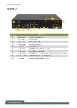
Page 14: ...NCA 1526 User Manual 14 ...

Page 15: ...onnectors and jumpers on the motherboard layout FAN2 FAN1 JOPEN1 J80PORT 1 DYING GASP1 ATX1 CONN1 SW2 SW1 JDCIN1 COM1 USB1 RJ3 RJ4 SFP1 SFP2 LAN1 DYING_GASP2 J16 J5G_1 J14 M2_1 JRTC2 JRTC1 CON1 SATA1 LED1 JBAT1 JSPIROM1 MPCIE1 M2_2 JSIM2 J15 JSIM1 JP5V1 ...

Page 16: ...escription 1 V_BATTERY 2 GND COM1 Console Port Pin Description 1 COM1_RTS_N 2 COM1_DTR_N 3 COM1_TXD 4 LGND 5 LGND 6 COM1_RXD 7 COM1_DSR_N 8 COM1_CTS_N CON1 SATA Power Connector Pin Description 1 P12V 2 GND 3 GND 4 P5V CONN2 Power PIN Header Pin Description 1 GND 2 PWRON FAN1 System Fan Pin Description 5 SYSFANOUT 4 NC 3 FANIN 2 P12V 1 GND ...

Page 17: ..._OUT 2 SOC_LPC_LAD1 3 80PORT_RST 4 SOC_LPC_LAD0 5 SOC_LPC_FRAME_N 6 P3V3_S 7 SOC_LPC_LAD3 8 NC 9 SOC_LPC_LAD2 10 GND JOPEN1 Case Open Connector Pin Description 1 SIO_CASEOPEN0_N 2 GND JRTC1 Clear CMOS 1 2 NORMAL 2 3 CLEAR RTC Pin Description 1 P3V3_RTC 2 SOC_SRTCRST_N 3 GND JRTC2 Clear CMOS 1 2 NORMAL 2 3 CLEAR RTC Pin Description 1 P3V3_RTC 2 SOC_RTEST_N 3 GND ...

Page 18: ...iption 1 NC 2 P3V3 3 GND 4 P3V3 5 GND 6 PWROFF 7 USB2_SB_L_DP 8 W_DIS 9 USB2_SB_L_DN 10 NC 11 GND 12 NC 13 NC 14 NC 15 NC 16 NC 17 NC 18 NC 19 NC 20 NC 21 NC 22 NC 23 NC 24 NC 25 NC 26 NC 27 GND 28 UIM1_VPP1 29 USB3_HRX_L_DTX_N 30 UIM1_RST1 31 USB3_HRX_L_DTX_P 32 UIM1_CLK1 33 GND 34 UIM1_DAT1 35 USB3_HTX_L_DRX_N 36 UIM1_PWR 37 USB3_HTX_L_DRX_P 38 NC 39 GND 40 NC 41 NC 42 NC 43 NC 44 NC 45 GND 46 N...

Page 19: ...Description Pin Description 1 GND 2 P3V3 3 GND 4 P3V3 5 NC 6 NC 7 NC 8 NC 9 NC 10 NC 11 GND 12 NC 13 NC 14 NC 15 NC 16 NC 17 NC 18 NC 19 NC 20 NC 21 GND 22 NC 23 NC 24 NC 25 NC 26 NC 27 GND 28 NC 29 NC 30 NC 31 NC 32 NC 33 GND 34 NC 35 NC 36 NC 37 NC 38 NC 39 GND 40 NC 41 SATA_HRX_C_DTX_P 42 NC 43 SATA_HRX_C_DTX_N 44 NC 45 GND 46 NC 47 SATA_HTX_C_DRX_N 48 NC 49 SATA_HTX_C_DRX_P 50 NGFF_STORAGE_RST...

Page 20: ...ription Pin Description 1 NC 2 P3V3 3 NC 4 GND 5 NC 6 NC 7 CLKREQ_MPCIE_SLOT2 8 NC 9 GND 10 NC 11 CLK_PCIE_SLOT_N 12 NC 13 CLK_PCIE_SLOT_P 14 NC 15 GND 16 NC 17 NC 18 GND 19 NC 20 P3V3 21 GND 22 MINI_PCI_RST 23 PEX_RXN 24 P3V3 25 PEX_RXP 26 GND 27 GND 28 NC 29 GND 30 SMB_MPCIE_CLK 31 PEX_TXN_C 32 SMB_MPCIE_DATA 33 PEX_TXP_C 34 GND 35 GND 36 USB2_P0_DN_L 37 GND 38 USB2_P0_DP_L 39 P3V3 40 GND 41 P3V...

Page 21: ...D 12 NC 13 NC 14 NC 15 NC 16 NC 17 NC 18 NC 19 NC 20 NC 21 NC 22 UIM1_VPP1 23 NC 24 UIM1_RST1 25 NC 26 UIM1_CLK1 27 GND 28 UIM1_DAT1 29 USB3_HRX_L_DTX_N16 30 UIM1_PWR 31 USB3_HRX_L_DTX_P16 32 NC 33 GND 34 NC 35 USB3_HTX_L_DRX_N16 36 NC 37 USB3_HTX_L_DRX_P16 38 NC 39 GND 40 NC 41 NC 42 NC 43 NC 44 NGFF_LTE_RST 45 GND 46 NC 47 NC 48 NC 49 NC 50 NC 51 GND 52 NC 53 NC 54 NC 55 NC 56 NC 57 GND 58 NC 59...

Page 22: ...2 M2_LTE SIM Card Slot Pin Description Pin Description C1 UIM1_PWR C4 UIM1_DAT1 C2 UIM1_RST1 C5 UIM1_VPP1 C3 UIM1_CLK1 C6 GND SW1 Reset Button Pin Description Pin Description 4 GND 3 GND 2 GND 1 SW_RST_GP_N SW2 Power Button Pin Description Pin Description 4 PWRON 2 GND 3 PWRON 1 GND L2 PRLED L1 SUSLED Pin Description 1 GND 2 SATA_TX_DP_C 3 SATA_TX_DN_C 4 GND 5 SATA_RX_DN_C 6 SATA_RX_DP_C 7 GND ...

Page 23: ... SEL 0 Host 1 Card1 SIM Socket for M2_1 LTE 1st SIM Card J5G_1 5G Module Selection Pin Header 1 2 3 4 5 6 7 8 9 10 short for EM9190 remove for FM980n Pin Description Pin Description 1 PCIE_DIS 2 1 8V 3 VBUS_SENSE 4 1 8V 5 EM9190_VCC1 6 1 8V 7 EM9190_VCC2 8 1 8V 9 EM9190_VCC3 10 1 8V JP5V1 5V Power Connector for Feed Wi Fi 6 Module Pin Description 1 GND 2 12VSB 3 GND 4 12VSB Pin Description 1 P3V3 ...

Page 24: ...SFP 0_RS0 3 GND 1 Dying Gasp Board Pin Header1 Pin Description Pin Description 1 P3V3_STBY 2 P3V3 3 P3V3_STBY 4 P3V3 5 P3V3_STBY 6 P3V3 7 GND 8 GND 9 GND 10 GND 11 GND 12 GND 13 P12V_UNDERVOLTAGE 14 RS_4 DYING_GASP2 Dying Gasp Board Pin Header 2 Pin Description Pin Description 1 RESET_STATUS 2 EN_SCAP_CHARGE 3 SCAP_STATUS_FULL 4 DGPFI 5 NC 6 NC ...

Page 25: ...ions to shut down the device completely and wear ESD protection gloves when handling the installation steps 1 Power off the system and remove all power connections 2 Locate and remove the six 6 screws on the chassis cover 3 Gently slide the chassis cover away from the system and lift the cover to remove Top Side Right Side Left Side ...

Page 26: ...M memory module 1 Power off the system and open the chassis cover 2 Locate the system memory slot 3 Align the notch of the module with the socket key in the slot Insert the pins at 30 degrees into the socket key until it is fully seated 4 Push down on the module until the slot latch catches and clicks into place Notch Socket Key Click Click ...

Page 27: ...Power off the system and open the chassis cover 2 Locate the M 2 slot on the motherboard 3 Align the notch of the M 2 memory card with the socket key in the pin slot 4 Insert the M 2 memory card pins at 30 degrees into the socket until it is fully seated 5 Push down on the module card and secure it with a screw Notch Socket Key ...

Page 28: ...d 1 Power off the system and open the chassis cover 2 Locate the mPCIe slot on the motherboard 3 Align the notch of the Wi Fi module card with the socket key in the pin slot 4 Insert the Wi Fi module card pins at 30 degrees into the socket until it is fully seated 5 Push down on the module card and secure it with a screw Installing Wi Fi Antennas Notch Socket Key A1 A2 ㄉ Rear Panel ...

Page 29: ...the two 2 antenna IPEX connectors on the Wi Fi module card 2 Connect the RF cables to the IPEX connectors on the Wi Fi module card and screw the other end of the cables in the antenna holes 3 Then screw on the antennas on the outside of the system A1 A2 ㄉ Wi Fi Module Wi Fi Module ...

Page 30: ...stallation 1 Power off the system and open the chassis cover 2 Locate the M 2 slot on the motherboard 3 Align the notch of the 5G module card with the socket key in the pin slot 4 Insert the 5G module card pins at 30 degrees into the socket until it is fully seated 5 Push down on the module card and secure it with a screw Installing 5G Antennas Notch Socket Key Rear Panel Front Panel A1 A2 ㄉ A3 A4...

Page 31: ...e two four 4 antenna IPEX connectors on the 5G module card 2 Connect the RF cables to the IPEX connectors on the 5G module card and screw the other end of the cables in the antenna holes 3 Then secure the four 4 antennas to the front and rear panel of the system A1 A2 ㄉ A3 A4 ㄉ 5G Module 5G Module 5G Module 5G Module ...

Page 32: ... cover Unscrew the two 2 screw securing the cover 3 Gently remove the SIM slot cover 4 Insert and push the Nano SIM card gold contacts facing downwards all the way in until it clicks into place Repeat if dual Nano SIM cards will be place 5 To remove the Nano SIM cards use your fingertips to push it once to have the card automatically eject 6 Place the slot door back and tighten the one 1 screw ...

Page 33: ...e PoE Module Kit includes 1x PoE Module 3x Spacer Standoff Pillar Studs 1x Power Adapter 2 Power off the system and open the chassis cover 3 Locate the PoE Module slot placement 4 Remove the three 3 screws 5 Replace the three 3 screws with the spacer standoff pillar studs PoE Module Power Charger Spacer Standoff Pillar Studs 5 ...

Page 34: ...o the chassis rear opening spot and insert the bottom pins into JPOE connector pins 7 Screw in the original three 3 screws to secure the PoE module board 8 Connect the power source pin to the power adapter Power Source Pin JPOE Connector Pins Front Panel View ...

Page 35: ...w 1 Boot up the system 2 Pressing the Tab or Del key immediately allows you to enter the Setup utility and then you will be directed to the BIOS main screen The instructions for BIOS navigations are as below Note The images in the following section are for reference only Control Keys Description select a setup screen select an item option on a setup screen Enter select an item option or enter a su...

Page 36: ...ernel version CRB code base X64 Compliancy UEFI version PI version Project Version BIOS release version Build Date and Time MM DD YYYY Access Level Administrator User System Date To set the Date use Tab to switch between Date elements Default Range of Year 2005 2099 Default Range of Month 1 12 Days dependent on Month System Time To set the Date use Tab to switch between Date elements ...

Page 37: ...NCA 1526 User Manual 37 Select the Advanced menu item from the BIOS setup screen to enter the Advanced setup screen Users can select any of the items in the left frame of the screen ...

Page 38: ... show Security Device TCG EFI protocol and INT1A interface will not be available SHA 1 PCR Bank Enabled Disabled Enables or disables SHA 1 PCR Bank SHA256 PCR Bank Enabled Disabled Enables or disables SHA256 PCR Bank Pending operation None TPM Clear Schedules an Operation for the Security Device NOTE Your computer will reboot during restart in order to change State of Security Device ...

Page 39: ...mode for Win8 Win10 TCG_2 Supports new TCG2 protocol and event format for Win10 or later Physical Presence Spec Version 1 2 1 3 Select to tell OS to support PPI Spec Version 1 2 or 1 3 NOTE Some HCK tests might not support 1 3 TPM 20 Interface Type TIS Select TPM 20 Device for the Communication Interface Device Select TPM 1 2 TPM 2 0 Auto TPM 1 2 will restrict support to TPM 1 2 devices while TPM ...

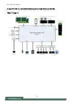
Page 40: ...NCA 1526 User Manual 40 ...

Page 41: ...NCA 1526 User Manual 41 Feature Options Description Serial Port Disabled Enabled Enable or Disable Serial Port COM Device Settings ...

Page 42: ...NCA 1526 User Manual 42 Feature Options Description Serial Port Disabled Enabled Enable or Disable Serial Port COM Device Settings ...

Page 43: ...NCA 1526 User Manual 43 Feature Options Description Smart Fan 2 Mode Manual mode SMART FAN IV Smart Fan 2 Mode Select ...

Page 44: ...NCA 1526 User Manual 44 Feature Options Description Case Open Enabled Disabled Enables or disables Case Open function ...

Page 45: ...NCA 1526 User Manual 45 Feature Options Description Status LED OFF GREEN RED Configures Status LED color ...

Page 46: ... Description Watch Dog Timer Enabled Disabled Enables or disables Watch Dog Timer function Watch Dog Timer Count Mode Second Mode Minute Mode Select Second Mode or Minute Mode Watch Dog Timer Time out Value 60 Watch Dog Timer Time out Value ...

Page 47: ...NCA 1526 User Manual 47 Feature Options Description COM0 Console Redirection Enabled Disabled Enables or disables Console Redirection ...

Page 48: ...7600 115200 Selects serial port transmission speed The speed must be matched on the other side Long or noisy lines may require lower speeds Data Bits 7 8 Data Bits Parity None Even Odd Mark Space A parity bit can be sent with the data bits to detect some transmission errors Stop Bits 1 2 Indicates the end of a serial data packet Flow Control None Hardware RTS CTS Flow Control can prevent data loss...

Page 49: ...ed With this mode enabled only text will be sent This is to capture Terminal data Resolution 100x31 Disabled Enabled Enables or disables extended terminal resolution Putty KeyPad VT100 LINUX XTERM86 SCO ESCN VT400 Selects FunctionKey and KeyPad on Putty ...

Page 50: ...NCA 1526 User Manual 50 Feature Options Description SR IOV Support Disabled Enabled If the system has SR IOV capable PCIe Devices this option enables or disables Single Root IO Virtualization Support ...

Page 51: ...d Disabled Enables or disables USB Mass Storage Driver Support USB transfer time out 1 sec 5 sec 10 sec 20 sec The time out value for Control Bulk and Interrupt transfers Device reset time out 1 sec 5 sec 10 sec 20 sec USB mass storage device Start Unit command time out Device power up delay Auto Manual Maximum time the device will take before it properly reports itself to the Host Controller Auto...

Page 52: ...d Enables Ipv4 HTTP Boot Support If IPV4 is disabled HTTP boot option will not be created Ipv6 PXE Support Disabled Enabled Enables Ipv6 PXE Boot Support If IPV6 is disabled PXE boot option will not be created Ipv6 HTTP Support Disabled Enabled Enables Ipv6 HTTP Boot Support If IPV6 is disabled HTTP boot option will not be created PXE boot wait time 0 Wait time to press ESC key to abort the PXE bo...

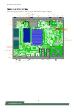
Page 53: ...NCA 1526 User Manual 53 ...

Page 54: ...ture Options Description SDIO Access Mode Auto ADMA SDMA PIO Auto Option Access SD device in DMA mode if controller supports it otherwise in PIO mode DMA Option Access SD device in DMA mode PIO Option Access SD device in PIO mode ...

Page 55: ...NCA 1526 User Manual 55 Feature Options Description Control PXE Boot from Disabled Lan1 Lan2 Lan3 Lan4 Control PXE Boot from which Lan ...

Page 56: ...NCA 1526 User Manual 56 Feature Options Description TruOpt Optimize Manual Lanner optimization ...

Page 57: ...rm Setup screen Users can select any of the items in the left frame of the screen Feature Options Description PCH IO Configuration None PCH Parameters Server ME Configuration None Configure Server ME Technology Parameters System Event Log None Press Enter to view or change the event log configuration ...

Page 58: ...ature Options Description PCH SATA Configuration None Device Options settings Restore AC Power Loss Power On Power Off Last State Select S0 S5 for ACPI state after a G3 Serial IRQ Mode Quiet Continuous Configure Serial IRQ Mode ...

Page 59: ...6 User Manual 59 SATA Configuration Feature Options Description SATA Configuration Disabled Enabled SATA test settings Aggressive LPM Support Disabled Enabled Enable PCH to aggressively enter link power state ...

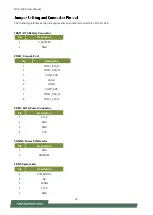
Page 60: ...NCA 1526 User Manual 60 ...

Page 61: ...NCA 1526 User Manual 61 Feature Options Description System Errors Disabled Enabled System Error Enable Disable setup options ...

Page 62: ...Options Description Processor Configuration None Displays and provides option to change the Processor Settings Memory Configuration None Displays and provides option to change the Memory Settings IIO Configuration None Displays and provides option to change the IIO Settings Advanced Power Management Configuration None Displays and provides option to change the Power Management Settings ...

Page 63: ...Enabled MLC Spatial Prefetcher MSR 1A4h Bit 1 Extended APIC Disabled Enabled Enables disables extended APIC support Note This will enable VT d automatically if x2APIC is enabled Enable Intel R TXT Disabled Enabled Enables Intel R TXT VMX Disabled Enabled Enables the Vanderpool Technology which takes effect after reboot Enable SMX Disabled Enabled Enables Safer Mode Extensions AES NI Disabled Enabl...

Page 64: ...NCA 1526 User Manual 64 Per Socket Configuration Feature Options Description Core Disable Bitmap Hex 0 0 Enable All cores FFFFFFFFFFF Disable all cores ...

Page 65: ...NCA 1526 User Manual 65 Feature Options Description Memory Topology None Displays memory topology with Dimm population information ...

Page 66: ...onfiguration menu PCI E ASPM Support Global No Per Port L1 Only This option enables disables the ASPM support for all downstream devices PCIe Extended Tag Enable Auto No Yes Auto Enable BIOS sets 8 bit Tag Field for PCIe Root Port EndPoint Disable BIOS sets 5 bit Tag Field for PCIe Root Port EndPoint PCIe Max Read Request Size Auto 128B 256B 512B 1024B 2048B 4096B Set Max Read Request Size in EndP...

Page 67: ... IOAT Configuration Feature Options Description Sck0 IOAT Config None None Disable TPH No Yes TLP Processing Hint disable Prioritize TPH Disabled Enabled Prioritize TPH Relaxed Ordering No Yes Relaxed Ordering Enable Disable ...

Page 68: ... for Directed I O VT d Feature Options Description Intel VT for Directed I O Disabled Enabled Enable Disable Intel Virtualization Technology for Directed I O VT d by reporting the I O device assignment to VMM through DMAR ACPI Tables ...

Page 69: ...NCA 1526 User Manual 69 Feature Options Description CPU P State Control None P State Control Configuration Sub Menu include Turbo XE etc ...

Page 70: ... Max Performance Max Efficient Set by Intel Node Manager Select the performance state that the BIOS will set before OS hand off Energy Efficient Turbo Disabled Enabled Energy Efficient Turbo Disable MSR 0x1FC 19 CPU Flex Ratio Override Disabled Enabled Enable Disable CPU Flex Ratio Programming CPU Core Flex Ratio 23 Non Turbo Mode Processor Core Ratio Multiplier ...

Page 71: ...left frame of the screen Feature Description Administrator Password If ONLY the Administrator s password is set it only limits access to Setup and is only asked for when entering Setup User Password If ONLY the User s password is set it serves as a power on password and must be entered to boot or enter Setup In Setup the User will have Administrator rights ...

Page 72: ...re Boot is activated when Platform Key PK is enrolled System mode is User Deployed and CSM function is disabled Secure Boot Mode Standard Custom Customizable Secure Boot mode In Custom mode Secure Boot Policy variables can be configured by a physically present user without full authentication ...

Page 73: ...lt keys on next re boot only when System in Setup Mode Restore Factory keys None Force System to User Mode Configure NVRAM to contain OEM defined factory default Secure Boot keys Enroll Efi Image None Allows the image to run in Secure Boot mode Enroll SHA256 hash of the binary into Authorized Signature Database db ...

Page 74: ...ture Options Description Setup Prompt Timeout 5 The number of seconds to wait for setup activation key 65535 means indefinite waiting Bootup NumLock State On Off Select the keyboard NumLock state Quiet Boot Disabled Enabled Enables or disables Quiet Boot option Choose boot priority from boot option group Choose specific boot device priority sequence from available Group device ...

Page 75: ...save the changes and exit from BIOS Setup in order for the new system configuration parameters to take effect The following window will appear after selecting the Save Changes and Exit option is selected Select Yes to Save Changes and Exit Setup Discard Changes and Exit Select this option to quit Setup without saving any modifications to the system configuration The following window will appear af...

Page 76: ... 76 Restore Defaults Restore default values for all setup options Select Yes to load Optimized defaults Note The items under Boot Override may not have the same image It would depend on the devices connected to the system ...

Page 77: ...tomer s expense 5 The following conditions are excluded from this warranty Improper or inadequate maintenance by the customer Unauthorized modification misuse or reversed engineering of the product Operation outside of the environmental specifications for the product 1 To obtain an RMA number simply fill out and fax the RMA Request Form to your supplier 2 The customer is required to fill out the p...

Page 78: ...NCA 1526 User Manual 78 When requesting RMA service please fill out the following form Without this form enclosed your RMA cannot be processed ...

Reviews: