background image

INSTALLATION, MAINTENANCE, 

AND SERVICE MANUAL 


ELECTRIC HOT WATER BOILERS 

(LW, HW) 


INDEX 

 
General Information 

Page 1


Installation  

Page 2

Typical Piping Diagram  

Page 2

Operation & Controls 

Page 3

Construction Page 

3

Start Up 

Page 4

Maintenance Page 

4

Element Replacement 

Page 5

Troubleshooting 
Literature Index 
 

Page 6
Page 7


GENERAL INFORMATION 


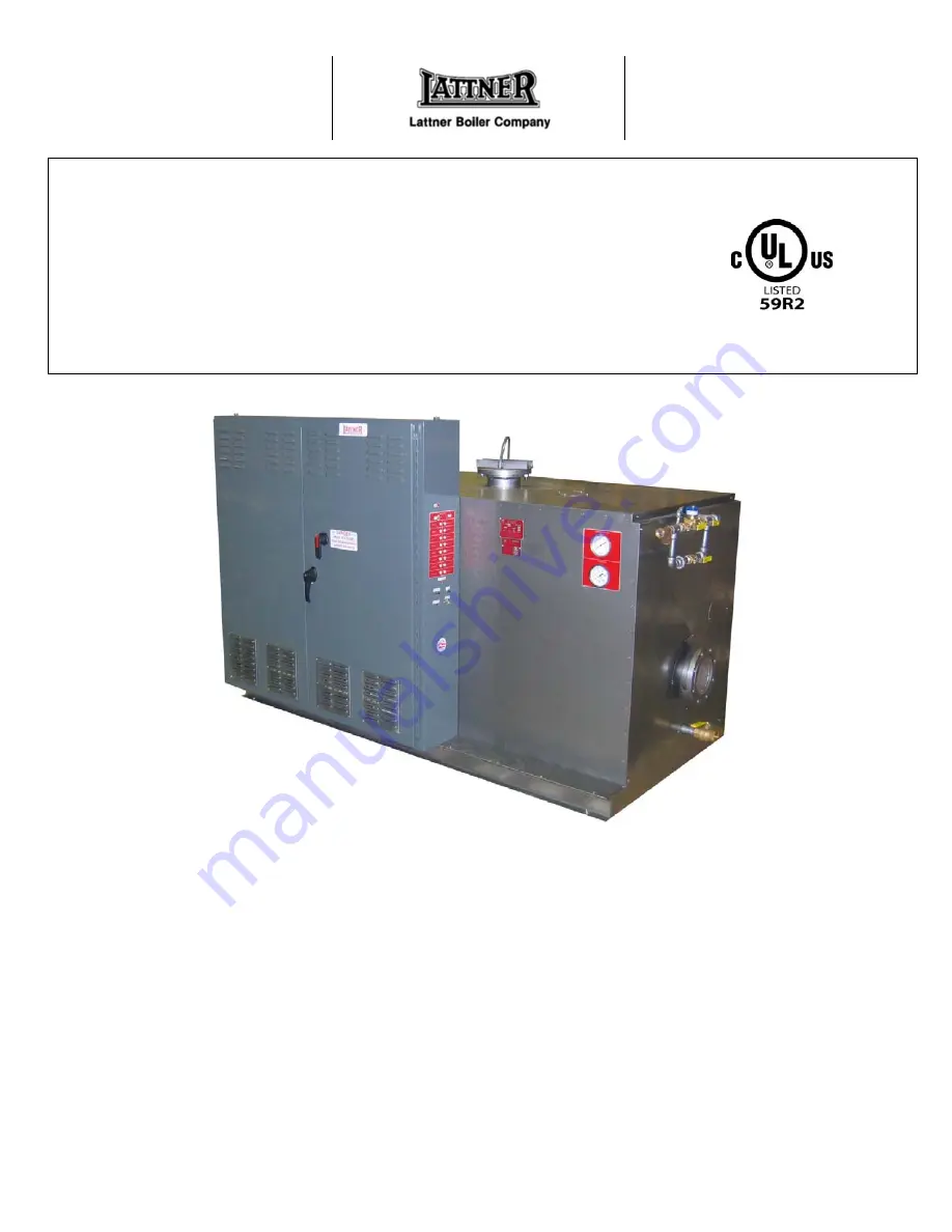
Vessel Construction

 – All vessels registered with the 

National Board of Boiler and Pressure Vessel Inspectors; 
Data reports are furnished. Comply with Section IV, ASME 
Code, stamped with “H”. Maximum design temperature and 
pressure is 250 degrees F and 160 psi if model “LW” boiler. 
Vessels above 250 degrees F and/or above 160 psi are 
designed to ASME Section I or Section VII  and are 
stamped “S” or “U”; model number designation is “HW”. 
 

Heating Elements

 – Removable, incoloy sheathed electric 

heating elements are mounted in 150 lb. ASME blind 
flanges with plated steel compression fittings. Complete 
flange assembly is inserted horizontally into vessel and 
bolted in place. 

UL Listing 

– Under file No. E30432 up to 600 volts. 


Enclosure 

– Heavy gauge steel control panel and steel 

vessel enclosure are attached to a steel frame, mounted on 
a 4” channel base. All surfaces are protected against 
corrosion with durable baked finish. 
 

Insulation

 – Minimum 4” fiberglass on all sides. Minimizes 

heat loss from vessel and keeps enclosure temperature 
cooler. 


1

Summary of Contents for HW

Page 1: ... and 160 psi if model LW boiler Vessels above 250 degrees F and or above 160 psi are designed to ASME Section I or Section VII and are stamped S or U model number designation is HW Heating Elements Removable incoloy sheathed electric heating elements are mounted in 150 lb ASME blind flanges with plated steel compression fittings Complete flange assembly is inserted horizontally into vessel and bol...

Page 2: ... is installed on a level noncombustible surface Lifting lugs welded directly to the pressure vessel are provided 5 Required access see certified print for exact dimensions Front 36 minimum Rear 12 minimum Top 36 minimum Element removal 64 minimum Side opposite element flange 12 minimum 6 Install drain and relief valves 7 Make water inlet and outlet piping connections 8 Wire supply conductors to ma...

Page 3: ...vent a power surge after power interruption the controller will reset automatically to the OFF position when power is restored Normal sequencing then stages the heating elements in accordance with thermostat requirements Gauges Pressure and temperature gauges are mounted on control cabinet front panel Gauges indicate working pressure and temperature of the boiler Safety Valve An ASME pressure reli...

Page 4: ...rol panel will come on Press low water reset button to establish control after boiler is filled 10 As water temperature increases check pressure and temperature gauges for proper indication Open vent cock again to purge air for the boiler 11 After 8 24 hours of operation check system water Ph with test kit or litmus paper Ph should read 7 5 to 8 5 If test is too acidic less than 7 0 add neutralize...

Page 5: ...riven out from the water side of the flange with a drift punch or other suitable tool 12 Install the new element blade through the separator plates and element flange The sheath of the element blade should protrude about 3 4 to 1 inch past the face of the flange 13 Slip the bronze ferrule onto the element blade Screw the compression nut into the flange and tighten to approximately 40 50 Ft Lb torq...

Page 6: ...tons on low water and high limits 2 Water temperature too low Operating control set too low or not operating properly oversized circulator pump or faulty elements fuses contactors wiring 3 Water temperature is too high Operating control is set too high or not operating properly undersized circulator pump or not operating properly 4 Water temperature correct but building is cold Circulator pump not...

Reviews: