background image

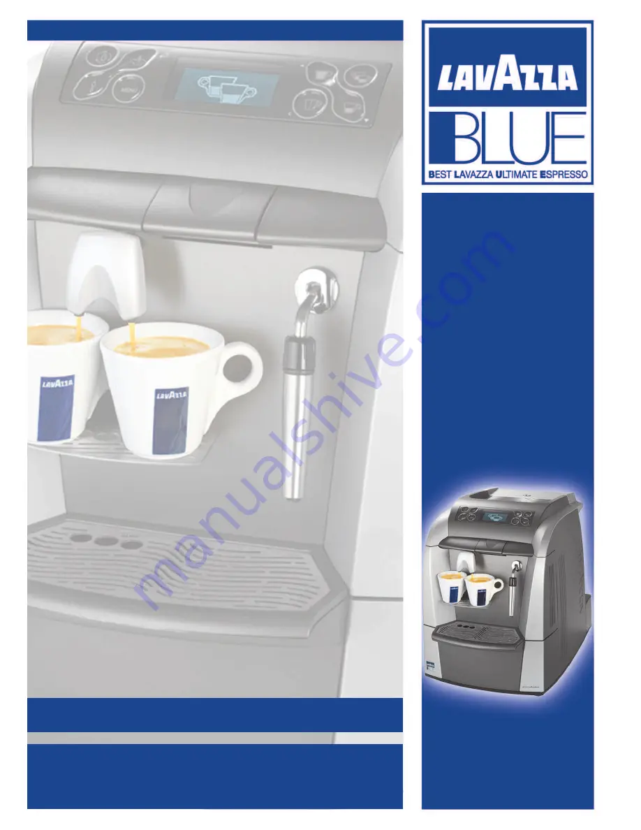
LB 2300-2301-2302-2311-2312

MAINTENANCE MANUAL FOR

TECHNICAL ASSISTANCE

M

ANUAL CODE

10083445 / R

EL

. 0.00 / A

PRIL

2010

Summary of Contents for LB2300 SINGLE CUP

Page 1: ...LB 2300 2301 2302 2311 2312 MAINTENANCE MANUAL FOR TECHNICAL ASSISTANCE MANUAL CODE 10083445 REL 0 00 APRIL 2010...

Page 2: ...le cup 230 V Steam Machine code 10080712 LB 2311 Single cup 120 V Steam Machine code 10080631 LB 2312 Double cup 120 V Steam Machine code 10080632 Manual code 10083445 Rel 0 00 Edition 04 2010 Copyrig...

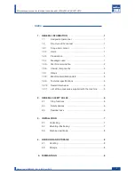
Page 3: ...2 9 Technical specifications 5 1 2 10 Overall dimensions 5 1 2 11 List of the accessories supplied with the machine 5 2 GENERAL SAFETY RULES 6 2 1 Stop functions 6 2 2 Safety devices 6 2 3 Residual ri...

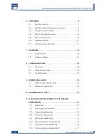
Page 4: ...leshooting 30 9 OPERATIONAL LOGIC 35 9 1 Reset of used capsule drawer 35 9 2 Reserve for product end 35 10 RECOMMENDED TOOLS 36 11 MOUNTING AND DISASSEMBLY OF THE MACHINE COMPONENTS 37 11 1 Upper body...

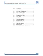
Page 5: ...ssembly 50 11 12 Capacitive sensor disassembly 52 11 13 Transformer disassembly 53 11 14 Coffee thermostat disassembly 55 11 15 Boiler disassembly 56 11 16 Gear motor disassembly 57 11 17 Perforator f...

Page 6: ......

Page 7: ...he personal protective equipment Warning The WARNING messages are displayed before pro cedures that if not observed could cause damage to the machine Warning If this manual is damaged or lost a new co...

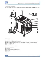
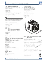
Page 8: ...ng spout the dispensing spout allows brewing 1 or 2 coffees according to the model 5 Cup support small cups 6 Cup support mugs 7 Used capsule drawer and drip tray 8 Service area access door 9 Power co...

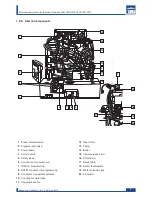
Page 9: ...ing 9 Connector for payment systems 10 Coupling for water tank 11 Capacitive sensor 3 Manual code 10083445 Rel 0 00 April 2010 Maintenance manual for technical assistance LB 2300 2301 2302 2311 2312 1...

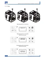
Page 10: ...manual for technical assistance LB 2300 2301 2302 2311 2312 Dispensing spout for 2 products C Steam hot water pipe Dispensing spout for 1 product B Steam hot water pipe Dispensing spout for 1 product...

Page 11: ...g Water tank capacity 4 litres Capsule container capacity Max 20 Manufacturer Machine name Serial number Power supply voltage V and frequency Hz Power consumption W Water mains pressure MPa Note In ca...

Page 12: ...nual carefully and the follo wing general safety rules 2 1 Stop functions To stop the machine turn the main switch to 0 OFF 2 2 Safety devices Two Klixon thermostats with manual reset avoid any overhe...

Page 13: ...it Remove the machine protections and the equipment contained in the package Take the machine out Warning It is prohibited to install the machine outside or in places where water or steam jets are use...

Page 14: ...arry out lifting and positioning with care Do not shake the machine 4 2 Storage The machine should be stored according to the follo wing conditions minimum temperature above 4 C maximum temperature be...

Page 15: ...0 Cap 01 DOUBLE CUP WITH STEAM SINGLE CUP WITH STEAM SINGLE CUP 7 7 8 8 9 9 6 6 1 10 0 1 11 1 2 2 1 1 4 4 3 3 5 5 9 Manual code 10083445 Rel 0 00 April 2010 Maintenance manual for technical assistance...

Page 16: ...again the button 04 Long coffee button Press this button and the machine dispenses a long coffee dose programmed by the service provider 05 Espresso button Press this button and the machine dispenses...

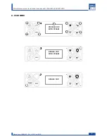
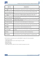
Page 17: ...to conclude automatically The machine is warming up Wait for this step to conclude automatically The machine is performing the circuit rinse cycle with fresh water Wait for the rinse cycle to end aut...

Page 18: ...be emptied though further products can still be dispensed With the machine stopped and switched on remove the used capsule drawer and empty it Indicates that the used capsule drawer must be emptied be...

Page 19: ...s seat Insert the used capsule drawer The machine alerts that the water tank should be filled though further product can still be dispensed Fill the water tank The water tank is empty Fill the water t...

Page 20: ...ogramming service provider To access the programming menu carry out the follo wing Turn the machine off using the on off switch Turn the machine on using the on off switch and while the hourglass show...

Page 21: ...ers when they are made editable using the OK button Page down change button This button allows Scrolling the pages within a menu Changing the parameters when they are made editable using the OK button...

Page 22: ...cc 1 2 2 3 Free prod dose Default 615 Maximum amount of manually dispensed product this is a numerical parameter with no physical cor respondent e g cc 1 2 2 2 Double dose prod dose Default 210 Quant...

Page 23: ...ed capsule drawer removed this delay applies only if the relevant alarm signal is shown After this time the warning or the alarm signal is cancelled Values 0 255 seconds 1 2 10 Contrast Default 35 To...

Page 24: ...digits for accessing the password function 2 1 Date and time 2 1 1 Time Set time hours and minutes 2 1 2 Date 2 1 2 1 Day Set day 2 1 2 2 Month Set month 2 1 2 3 Year Set year 2 1 2 4 Day of the week...

Page 25: ...ince the last initialisation 2 2 2 4 Prod 3 from Init Read only Number of product type 3 manual dose dispensed since the last initialisation 2 2 2 5 Prod 4 from Init Read only Number of product type 4...

Page 26: ...s at least one error in the list 0 oldest error 5 last error 2 7 2 Log reset Default No Yes clears the list of recent errors 2 7 3 Error reset Default No Yes clears the non self resolving Out of servi...

Page 27: ...ratura std 100 V C V 1 2 1 Temperatura std 100 V C V 1 2 1 Temperatura std 100 V C V 1 2 1 Temperatura std 100 The value is made editable and under the digit to be changed the symbol appears Press one...

Page 28: ...i cablaggio LB2300 Base LB 2300 Cap 04 REV00 Dicembre 2008 7 DIAGRAMS 7 1 Wiring diagram LB 2300 22 Manual code 10083445 Rel 0 00 April 2010 Maintenance manual for technical assistance LB 2300 2301 23...

Page 29: ...cablaggio LB2300 Top 2 6 LB 2300 Cap 04 REV00 Dicembre 2008 LB 2301 LB 2302 LB 2311 LB 2312 23 Manual code 10083445 Rel 0 00 April 2010 Maintenance manual for technical assistance LB 2300 2301 2302 2...

Page 30: ...raulic diagram LB 2300 6 6 Schema idraulico LB2300 Base LB 2300 Cap 04 REV00 Dicembre 2008 24 Manual code 10083445 Rel 0 00 April 2010 Maintenance manual for technical assistance LB 2300 2301 2302 231...

Page 31: ...idraulico LB2300 Top 5 6 LB 2300 Cap 04 REV00 Dicembre 2008 LB 2301 LB 2302 LB 2311 LB 2312 25 Manual code 10083445 Rel 0 00 April 2010 Maintenance manual for technical assistance LB 2300 2301 2302 23...

Page 32: ...LINE 2 1 Microswitch of the brew unit in working position up 2 Microswitch of the brew unit in resting position down 3 Microswitch of the brew unit presence 4 Microswitch of the used capsule drawer 5...

Page 33: ...nce 4 Microswitch of the used capsule drawer 5 Microswitch of the capsule presence 6 Microswitch of the capsule loading tray 7 Sensor of the water level 8 Magnet of flowmeter turbine 9 Microswitch of...

Page 34: ...e level is reached level 2 TEST MODE 2 In this level the operation of the pump the coffee solenoid valve the steam solenoid valve are chec ked the last two only for De Luxe model By pressing UP the st...

Page 35: ...an be changed By pressing UP the display contrast is increased By pressing DOWN the display contrast is diminished The number shown in the fourth line of the display indicates the set contrast value T...

Page 36: ...power board is broken CPU board is broken The wiring is interrupted 12 Zero Crossing miss The alarm can be reset by switching the machine off Unsuitable net frequency Neither 50Hz nor 60Hz Check the...

Page 37: ...enoid valve is occluded or broken The pump is broken or interrupted The thermal switch of the pump is off The boiler is occluded The Power board TRIAC is broken Command from CPU board 27 Alarm of the...

Page 38: ...d 54 Boiler temperature error Boiler temperature out of control e g the boiler is on and the tem perature does not increase The boiler safety thermostat is activated The boiler heating unit is broken...

Page 39: ...allowed to take the brew unit to the resting position The capsule is blocked on the brew unit The brew unit is jammed or blocked Gears blocked or sticking 83 Out of maximum time for dispensing The ala...

Page 40: ...d the dispensing position without stop ping The microswitch for working posi tion is broken or disconnected Inverted wiring on the motor of the gear motor 87 The microswitch for resting position was a...

Page 41: ...r will be asked to fill the water tank Example 10 cc Livello acqua iniziale Sentore capacitivo 90 cc fisso reale non impostabile via SW Ex the sensor detects the water presence 10 cc hypothesis 1 a pr...

Page 42: ...cers Attention All the mechanical connections and cables use safety faston If there is a faston cover squeeze the plastic as indicated in the figure and pull 10 RECOMMENDED TOOLS To carry out the appl...

Page 43: ...capsule drawer separate and dispose of the used capsule empty the waste water Loosen the indicated screws Press the PUSH button and remove the brewing unit from its seat 37 Manual code 10083445 Rel 0...

Page 44: ...p using its handle Loosen the body screws and the fixing nut of the tum bler lock Remove the water tank lid using the key 38 Manual code 10083445 Rel 0 00 April 2010 Maintenance manual for technical a...

Page 45: ...s indicated in the figure For the version equipped with cup warmer remove the power supply connector of the cup warmer and the ground faston connector now the body is disengaged 39 Manual code 1008344...

Page 46: ...move the clip which fixes the steam pipe to the door and extracts the pipe from its seat When the connectors are removed extract the body completely 40 Manual code 10083445 Rel 0 00 April 2010 Mainten...

Page 47: ...heat Be careful when ope rating under these conditions 11 2 GACO gasket replacement Lever with a screwdriver to remove the gasket cover Remove the gasket with a screwdriver After placing the new gask...

Page 48: ...ove the indicated screws 2 1 Inside the compartment there are 1 the receptacle of the power cord 2 the fuse housing 42 Manual code 10083445 Rel 0 00 April 2010 Maintenance manual for technical assista...

Page 49: ...iagnostic and reprogramming of the machine parameters and software 2 Connector for payment systems 3 Serial port for P C for reprogramming of the machine parameters and software 2 3 1 43 Manual code 1...

Page 50: ...e by using a spanner 11 6 Steam solenoid valve disassembly Disconnect the faston loosen the nut and remove the coil Remove the steam pipe 44 Manual code 10083445 Rel 0 00 April 2010 Maintenance manual...

Page 51: ...s the pipe to the Teflon piece by using a screwdriver Loosen the indicated screws Loosen the indicated screws 45 Manual code 10083445 Rel 0 00 April 2010 Maintenance manual for technical assistance LB...

Page 52: ...cover and loosen the indicated screws Reposition the cover correctly and remove the cup warmer plate Remover the gasket and replace it if necessary 46 Manual code 10083445 Rel 0 00 April 2010 Mainten...

Page 53: ...ule release coil should be disassembled by lowering the stop on the back Detach the indicated supports by levering with a screw driver and remove the electric and hydraulic connec tions 11 9 Pump disa...

Page 54: ...ract the turbine by lifting it upwards Disconnect the electrical connection Disconnect the hydraulic connections 48 Manual code 10083445 Rel 0 00 April 2010 Maintenance manual for technical assistance...

Page 55: ...urbine from the machine Turn the turbine top to open it Clean the rotary section of the turbine 49 Manual code 10083445 Rel 0 00 April 2010 Maintenance manual for technical assistance LB 2300 2301 230...

Page 56: ...remove the capsule presence microswitch Remove the upper support from the base lifting it up Loosen the indicated screws to access the inside of the unit A 50 Manual code 10083445 Rel 0 00 April 2010...

Page 57: ...ading tray is open To remove the microswitch lightly widen the two stops and lift it up The unit can be checked by removing it from its seat as indicated in the figure 51 Manual code 10083445 Rel 0 00...

Page 58: ...ve sensor from its seat Loosen the indicated screw to access the sensor The capacitive sensor is maintained in its seat by an adhesive film 52 Manual code 10083445 Rel 0 00 April 2010 Maintenance manu...

Page 59: ...former is situated under the board on the right side of the machine Loosen the indicated screws Loosen the indicated screws 53 Manual code 10083445 Rel 0 00 April 2010 Maintenance manual for technical...

Page 60: ...Lift the plate up Loosen the indicated screws 54 Manual code 10083445 Rel 0 00 April 2010 Maintenance manual for technical assistance LB 2300 2301 2302 2311 2312...

Page 61: ...ct the electric connections of the thermostats A Loosen the indicated screw Lever with a screwdriver to disengage the retainer A 55 Manual code 10083445 Rel 0 00 April 2010 Maintenance manual for tech...

Page 62: ...sassembly Unscrew the nut X remove the fork and the Teflon pipe Y and W disconnect the silicone pipe Z Loosen the indicated screws Z Y X W 56 Manual code 10083445 Rel 0 00 April 2010 Maintenance manua...

Page 63: ...cro switch of the brew unit presence Y the transparent cover must be disassembled After loosening the screws remove the cover now you can access 1 the motor 2 the gears 3 the microswitch of the brew u...

Page 64: ...or filter disassembly Remove the brew unit Loosen the indicated screws Loosen the indicated screws 58 Manual code 10083445 Rel 0 00 April 2010 Maintenance manual for technical assistance LB 2300 2301...

Page 65: ...nd extract the fixed container of the coffee capsule Loosen the indicated screws Remove the perforator P U S H P U S H 59 Manual code 10083445 Rel 0 00 April 2010 Maintenance manual for technical assi...

Page 66: ...e rod to disengage it When the pin is disengaged press it with a finger to remove it from its position Extract the piston from the top 60 Manual code 10083445 Rel 0 00 April 2010 Maintenance manual fo...

Page 67: ...iston insert it again in its position as indicated in the figure Keeping pressed the piston press the rod into the slit of the piston until it is fixed in place 61 Manual code 10083445 Rel 0 00 April...

Page 68: ...d safe silicone grease the rails of the two inner sides of the brew unit Grease with food safe silicone grease the connecting rod and the rod 62 Manual code 10083445 Rel 0 00 April 2010 Maintenance ma...

Page 69: ...d in the figure all the connections that are connected to the board and lift the support up Remove the two connections and loosen the indicated screws Note Before removing the board make sure that all...

Page 70: ...tive boards and loosen the indicated screws to access the keyboard boards Remove the gasket by lift it up The two boards are attached with an adhesive lever to remove them 64 Manual code 10083445 Rel...

Page 71: ...ach the flat cable that connect the two capacitive boards and loosen the indicated screws to access the keyboard boards Remove the display and replace it 65 Manual code 10083445 Rel 0 00 April 2010 Ma...

Page 72: ...he clamp use the proper pliers Check the correct clamping A and positioning To remove the clamp use the pincers as indicated in the figure B A B 66 Manual code 10083445 Rel 0 00 April 2010 Maintenance...

Page 73: ......

Page 74: ......

Reviews: