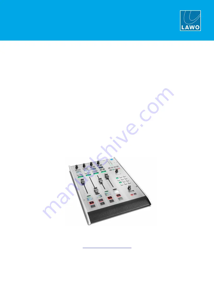
background image

To obtain the latest documentation and software downloads, please visit:

Edition: Tuesday, March 9, 2021

Version: 6.6.0/2

User Manual

crystal

www.lawo.com/lawo-downloads

Summary of Contents for crystal

Page 1: ...To obtain the latest documentation and software downloads please visit Edition Tuesday March 9 2021 Version 6 6 0 2 User Manual crystal www lawo com lawo downloads...

Page 2: ...ers It cannot be guaranteed that all product names products trademarks requisitions regulations guidelines specifications and norms are free from trade mark rights of third parties All entries in this...

Page 3: ...126 9 Audio IO 138 10 Audio Mix Engine 161 11 Audio Utilities 222 12 Routing Matrix 226 13 Intercom 233 14 Control Surface Configuration 258 15 Configuring the Snapshots System 281 16 Connecting a Vi...

Page 4: ...for the following which indicate Notes points of clarification Tips useful tips and short cuts Attention alert you when an action should always be observed Further Information Mechanical drawings and...

Page 5: ...ortant Safety Instructions 2 Important Safety Instructions Please observe all of the instructions provided in the General Safety Information for Lawo Equipment booklet delivered with your devices Doub...

Page 6: ...l Version 6 6 0 2 6 459 3 The Hardware 3 The Hardware This chapter describes the hardware components and options Topics include System Components Controls Overview Control Surface Variants The Compact...

Page 7: ...tal Control Surface essential available in five main frame layouts Compact Engine essential all audio interfacing routing control and signal processing VisTool MK2 optional runs on an external PC to p...

Page 8: ...m defined while some is programmable by the configuration 3 2 1 Fader Module 951 41 10 Fader Module Each Fader Module provides four identical fader strips each with an ACCESS key 100mm manual fader ba...

Page 9: ...ed labels Both modules include two rotary encoders VCAs1 2 and more MF Keys 1 to 16 with foil printed labels All MF Keys and VCAs are defined by the configuration 3 2 3 Programmable Functions Programm...

Page 10: ...ease the fader count or create a split frame surface In total the control surface can include any number of extenders as long as the maximum number of faders does not exceed 24 Each frame connects to...

Page 11: ...4 fader main frame supports a single Central Module while all other sizes include two 4 fader 8 fader 12 fader 12 fader split 16 fader 4 fader extender 3 3 2 Placement Options crystal is designed to...

Page 12: ...te as main and redundant connections 4 ETHERNET The ETHERNET port connects other devices to the Compact Engine control system Applications include remote control via TCP IP networking to other product...

Page 13: ...switched functions 11 WCLK IN OUT WCLK IN can be used to connect an external sync reference The sync reference options are MADI WCLK IN AES3 or Internal WCLK OUT always provides an output of the curr...

Page 14: ...crystal User Manual Version 6 6 0 2 14 459 3 The Hardware 3 5 Key Panels See Key Panel Control...

Page 15: ...6 6 0 2 15 459 4 The Standard Configuration 4 The Standard Configuration This chapter describes the standard configuration Topics include Introduction Available Sources Available Buses Default Audio...

Page 16: ...ters in this manual describe the possible configuration options For more information on using the tool please refer to the ON AIR Designer User Guide If you are using VisTool MK2 then there is an acco...

Page 17: ...1 mic line KICK mono Input 2 mic line GST 1 mono Input 3 mic line GST 2 mono Input 4 mic line TEL 1 mono Input 5 line TEL 2 mono Input 6 line LINE stereo Inputs 7 8 line EXT 1 stereo AES3 INPUT rear...

Page 18: ...tereo post fader Lim see Default Audio REC stereo pre or post fader Lim AUX stereo pre or post fader Lim PFL stereo pre fader PFL appears on the SPEAKER and DJ HP outputs Conf Bus Name Format Pickup P...

Page 19: ...uts the configuration loads the default audio assignments 4 4 1 Analog Inputs MIC LINE INPUT Compact Engine rear panel Input Number Source Name Format 1 DJ mono 2 KICK mono 3 GST 1 mono 4 GST 2 mono 5...

Page 20: ...rear panel Input Number Source Name Format 1 2 EXT 1 left right 3 4 EXT 2 left right 5 6 PLAYER 1 left right 7 8 PLAYER 2 left right 4 4 4 Digital Outputs AES3 OUTPUT Compact Engine rear panel Output...

Page 21: ...ty 8 x GPI opto couplers and 8 x GPO silent CMOS relays are supported Typical GPI applications include Cough switch for MIC sources External talkback triggering Incoming call signaling for hybrid sour...

Page 22: ...0 2 22 459 5 Installation 5 Installation This chapter describes how to install the control surface and Compact Engine Topics include Installing the Control Surface Installing the Compact Engine Ground...

Page 23: ...contents of the shipping boxes and in the event of any transport damage contact your local Lawo representative or email support lawo com A list of serial numbers for all components is included with t...

Page 24: ...emove the button cap It helps to use a small screwdriver to lift up the button cap as the caps are recessed However you must take care not to scratch the surface 2 Insert the foil plate between the bu...

Page 25: ...ic to connect AC mains to the frame 1 x serial cable 485 0700 000 to connect to the RS 422 port for diagnostics Dust caps for the MADI connectors these will be mounted in the frame 1 x USB memory card...

Page 26: ...as the ones shown below When fitting the rack adapters and slide bars you must make sure that there is sufficient airflow through the device for cooling Front View Rear View Recessed Rack Adapters Con...

Page 27: ...ted with an IO card then take care to undo the correct screws DO NOT unscrew any connectors 3 Pull out the cover plate or existing IO card from its slot taking care not to damage any connectors Spare...

Page 28: ...a Torx T10 driver and imbus tool This procedure must NOT be performed while the frame is powered The Compact Engine carries highly sensitive electronic components and should be handled with care ALWAY...

Page 29: ...From above the unit remove the 3 plastic screws which will hold the MADI board in place 6 Unpack the new MADI board taking care to ensure safe ESD handling of the device 7 Carefully feed the MADI con...

Page 30: ...he two front panel screws to fix the MADI board in place If you are installing the internal MADI bridge option then continue on to the next topic before replacing the top cover 11 Alternatively replac...

Page 31: ...refore cannot support this option If the internal MADI bridge is not installed then the 952 38 IO card provides 8 bi directional streaming channels to and from the backplane This procedure must NOT be...

Page 32: ...sure safe ESD handling of the device 5 Insert the card into the left expansion slot so the card slides into the guides on both sides 6 Plug the free end of the CAT5 cable into the RJ45 connector on th...

Page 33: ...d through Ethernet or other signal connections Grounding of Audio Interfaces For compliance with AES3 digital interfaces should be connected to a field ground For microphones the ground from the devic...

Page 34: ...e the Compact Engine Power Supply appendix If both inputs are connected then the two feeds provide main and redundant power To connect AC power to the frame 1 Using the IEC cable provided connect your...

Page 35: ...o network crystal to other Lawo systems The connection can be made either directly or via a network switch When connecting via a network then this can be shared with other devices such as in the regul...

Page 36: ...th is 10 meters The port has two LEDs which indicate the following information LED Color State Meaning LED 1 left Green flashing data transfer LED 2 right System Run Green flashing control system runn...

Page 37: ...ged i e it must use a suitable network architecture all components must support multicast as opposed to unicast a proper Quality of Service QoS must be configured and so on Please DO NOT attempt to co...

Page 38: ...AC 0 5A 60V The connector is a 37 pin D type 8 WCLK IN OUT BNC The system can sync to external wordclock by connecting the clock signal to WCLK IN The WCLK OUT provides an output of the current syste...

Page 39: ...rnal sync and internal clock is handled automatically If external sync is not available then the Compact Engine can act as a sync master and distribute its internal clock to other devices via WCLK OUT...

Page 40: ...all the software and set up the system Topics include System Connections Required for Setup Powering On Checking the System Setting Up the Configuration PC Updating the Firmware Uploading a Configurat...

Page 41: ...switch or hub is not allowed If more than one frame is supplied then the CAN bus must be daisy chained On the last surface in the chain fit the CAN bus terminator supplied with the system to the CAN O...

Page 42: ...xtender module CAN IN 2 Then connect the extender module CAN OUT to the CAN IN on the main surface 3 Fit the CAN bus terminator supplied with the system to the CAN OUT on the main surface 4 Remember t...

Page 43: ...the device s IP address and the system run LED to the right of the RS422 connector begins to flash at regular intervals If the system run LED does not start to blink then the Compact Engine has an in...

Page 44: ...d in the VisTool MK2 User Guide 6 3 2 Configuring the Network Settings on the PC To establish a network connection to the Compact Engine you will need to configure the network settings for the PC s LA...

Page 45: ...reach the Summary window check the options and click Install the software is installed onto your computer this may take a few minutes By default files are installed in the location C Program Files On...

Page 46: ...alyses the current firmware revisions 3 In the system tree on the left use the and signs to open and close the unit For Compact Engine and Nova29 systems you should see two components System and Surfa...

Page 47: ...ogress is shown in the status bar An update can take several minutes Once the update is complete the Compact Engine will cold start Wait for the system to reboot and then click on the refresh button t...

Page 48: ...ction to one of the streaming ports The current network settings can be checked from the front panel display If ETHERNET B has not been configured for streaming then its default IP address 192 168 110...

Page 49: ...with an empty configuration Therefore you will need to reload your system configuration Configurations are are not cross compatible and so the Compact Engine mode MUST match that of the configuration...

Page 50: ...in the Hardware column according to the table shown below Select Continue to proceed Hardware Type Console 951 21 crystal 952 60 sapphire compact 4 Once the update is complete the system restarts sele...

Page 51: ...edit the IP Address field to match the Online indicators will update See Checking the Network Communication 4 If any changes have been made to the configuration then these must be saved before the tra...

Page 52: ...s for the system and press ENTER 4 You are asked to confirm so type Y to confirm press ENTER The syntax is case sensitive so be sure to enter a capital Y You will see the following messages if the IP...

Page 53: ...pplication by selecting START Program Files SoP Explorer 2 Select Unit New from the main menus enter the IP address of the Compact Engine and select OK to add the unit SoP Explorer connects to the Com...

Page 54: ...ET is 5 hours ahead The second part of the syntax specifies the start and end of Central European Summer Time CEST e g from month 3 week 2 day 0 time 2am the second Sunday in March until month 11 week...

Page 55: ...us speed is defined in the Project window CAN bus address is defined in the Frames Surface window The settings stored on each physical module are edited using the special functions mode On older Key P...

Page 56: ...t assign the same address to more than one module If you do so this can lead to control conflicts and odd behaviour of the surface Single frame Consoles By default each control surface frame ships wit...

Page 57: ...on has been customized then the operation may vary Topics include Basic Operations Fader Strip Control Resetting Fader Positions Source Specific Functions The Central Modules Assigning Fader Strips Ma...

Page 58: ...nd the Central Modules If the Compact Engine performs either a warm start or cold start while VisTool is running then the message System has been restarted appears on top of the Clock Timer Click on t...

Page 59: ...functions such as the system clock timer mic open indicator output metering and monitoring selections Other pages appear alongside the DOCK as needed For example press a fader strip ACCESS key and the...

Page 60: ...onents and so you can turn off the control surface and the Compact Engine by turning off the mains power To close VisTool press ALT F4 on your PC keyboard Note that closing VisTool on the control PC o...

Page 61: ...rameter control fader strip assign and bus assign modes the rotary control 1 and soft keys 2 provide alternative functions 3 ACCESS Key Use the ACCESS key to select a source for parameter control or a...

Page 62: ...gnal present takes priority In the configuration use the Source Color and Source Color Mode options to define the color coding and mode of operation The signal present thresholds are defined globally...

Page 63: ...h the fader open If a fader position needs to be reset then the source label will flash and you will see arrows indicating the correct level of the source To reset the fader position 1 Move the fader...

Page 64: ...INE TEL 1 and TEL 2 sources can be assigned onto the conference bus to create a mix minus for the source You must enable CONF on more than one source to activate the conference The conference system i...

Page 65: ...e left and PGM 1 output on the right The meters work in parallel with the meters on the DOCK 2 Ambient Light Detector This detector automatically adjusts the brightness of buttons and displays on the...

Page 66: ...ormation see Using the Local Snapshot Memories and local matrix 5 Monitoring Controls The remaining keys and rotary controls provide monitor source selection and volume control for the four monitor ou...

Page 67: ...s into strip assign mode and the Source Assignment buttons appear on VisTool Fader Strips source assign mode VisTool source assign view Scroll down for more sources On VisTool the buttons are color co...

Page 68: ...nment the fader label updates and the strip assign mode cancels Alternatively select REMOVE to remove the source the fader strip is cleared and strip assign cancels The CANCEL button cancels out of th...

Page 69: ...outer if using NetCom or Remote MNOPL protocols 7 7 2 Selecting a Matrix Pool Signal Group Signal Select Fader Label Display 1 Press down on the fader strip rotary control to step through the input pa...

Page 70: ...The fader strips switch into bus assign mode and their soft keys show the current assignments Yellow post fader Green off not assigned Red pre fader available for AUX buses only 2 Press a soft key to...

Page 71: ...n 6 6 0 2 71 459 7 Operation 7 8 2 Assigning a Bus to an Output By default the summing buses are assigned to a number of physical outputs The assignments can be changed or reset to the defaults from t...

Page 72: ...rameters please see Input Pan Parameters 7 9 1 Surround Panning If a surround bus is configured and surround parameters are enabled on the source then the sequence includes the following Left Center R...

Page 73: ...effectively you will need to ask the talent to speak into the microphone at their intended on air level 1 Start by asking the talent to speak and then turn on AutoGain by pressing the MIC source ACCES...

Page 74: ...e Signal Flow The DSP available for each source is defined by the configuration and cannot be changed by the user In the standard configuration each of the MIC sources comes fully configured with anal...

Page 75: ...control mode and on VisTool the Source Parameters page appears VisTool Source Parameters page Control Surface INPUT parameters VisTool shows all available parameters and so this is the best way to get...

Page 76: ...djust the input and pan parameters for the selected source The 16 soft keys and 4 rotary controls update and are labeled by the displays as shown above Then press a soft key e g Pad to turn the option...

Page 77: ...alue MIC Sources Surface Controls VisTool For a mono MIC source you can adjust input parameters in the analog domain before the A D converter AND in the digital domain after the converter The analog m...

Page 78: ...ith a 3dB gain offset SIDE the left input and right input are reversed left input to right side of channel and right input to left side of channel GAIN channel gain from 30dB to 18dB BASIS left right...

Page 79: ...e To access the dyanmics parameters press an ACCESS key followed by DYN on the Central Module The fader strip controls update to show the last page adjusted in our example the Compressor Surface Contr...

Page 80: ...time from 10ms to 5000ms For the ATT RLS control turn to adjust the attack time and then press down and turn to adjust the release time Both DYN and COMP must be enabled red for the compressor to be a...

Page 81: ...for all dynamics sections compressor expander gate and de esser automix EXP on off for the expander THRS threshold from 93dB to 27dB RATIO ratio from 1 1 to 1 0 1 Both DYN and EXP must be enabled red...

Page 82: ...ff for the gate THRS threshold from 93dB to 27dB ATT attack time from 0 16ms to 82ms RLS release time from 10ms to 5000ms For the ATT RLS control turn to adjust the attack time and then press down and...

Page 83: ...this is the amount of gain reduction applied to the sibilant frequencies o Values from 1 to 6 reduce the gain of the unwanted sibilant frequenices the higher the value the more gain reduction o Above...

Page 84: ...ser automixing AMix on off for AutoMix Weight adjusts the weighting factor of each source from 9 to 9 with a default mid point 0 Sources with a higher weight value get priority in the mix those with t...

Page 85: ...ively look at the Central Module LIM key lit limiter available To access the limiter parameters press an ACCESS key followed by LIM on the Central Module Surface Controls Limiter VisTool The following...

Page 86: ...o access the delay parameters press an ACCESS key followed by DLY on the Central Module Surface Controls Delay The following parameters are available for the delay module DELAY switches the prepared d...

Page 87: ...s high pass and low pass filters The filters can be used either as fixed slope filters 12dB per octave or shelving EQ To access the EQ parameters press an ACCESS key followed by EQ on the Central Modu...

Page 88: ...owing parameters are available Gain Low Mid and High Gain can be adjusted from 15dB to 15dB Frequency Low Mid and High Frequency can be adjusted from 20Hz to 18kHz Q press the or buttons to increase o...

Page 89: ...quency shelf High or Low Pass Filters In this mode the filter slope is fixed at 12dB per octave Therefore there is no Gain or Q value available The cut off frequency can be adjusted from 20Hz to 18kHz...

Page 90: ...automatically switches to the pre fader listen bus level It will return to the active monitor source once all PFL CUE selections are cleared PGM 1 always meters the PGM 1 output Both meters are stereo...

Page 91: ...r a Momentary 400ms sliding window or Short term 3s sliding window integration time The color indicates whether loudness is above or below the Target Level Light Blue equal to or below the Target Leve...

Page 92: ...sections are the dedicated MUTE and DIM buttons on the surface for the speaker outputs the split headphones option available for the MON DJ and the automatic dimming of the MON CR output by an active...

Page 93: ...and other options are then available via the Monitor Extension pop ups on VisTool These can be opened by pressing any of the wide buttons below the volume controls e g press CRM to open the extension...

Page 94: ...monitor sources and other options VisTool supports a Monitor Extension for each of the monitor sections To open an extension press the wide button below the section s volume control For example press...

Page 95: ...MON CR Extension MON STUDIO Extension MON DJ Extension MON GUEST Extension Split Headphones There is one additional option for MON DJ output called SPLIT When SPLIT is active red the DJ will hear dif...

Page 96: ...Key 4 at the bottom of the fader strip is programmed as PFL also known as CUE Multiple PFLs can be active to listen to a number of sources On a closed fader press PFL to route the source onto the ste...

Page 97: ...he clock appears big with the timer small However the functions can be reversed by clicking on the smaller of the two elements Clock big and Timer small Timer big and Clock small 7 13 3 System Clock T...

Page 98: ...ount down from a Preset value Use the START STOP and RESET keys on the Central Module to operate the timer START starts the timer from the last stop position time STOP stops the timer RESET resets the...

Page 99: ...STOP and RESET buttons When the count down reaches the Alarm time the numbers turn red to warn you that you are almost out of time If the count down reaches 00 00 then the timer starts to count back u...

Page 100: ...the Display name until such time as the System field is cleared 3 Once you have finished editing select OK to transfer the labels to the system the editor closes and the labels on the control surface...

Page 101: ...om the remote system For option one add a Box element to the VisTool project and link this to the Predefined User Text User Label Edit option For option two add a Logic VispageSwitch element to the ON...

Page 102: ...1 mix minus return there are no separate level controls for this output If the system is set to the DEFAULT audio then Connect the DJ headphones to HEADPHONE 1 Compact Engine rear panel Connect the g...

Page 103: ...o if you close the DJ fader the DJ s monitor feed reverts to a conference bus mix minus so they can rejoin the off air conversation if required 4 Finally open both the MIC 1 and MIC 2 faders Both the...

Page 104: ...esigner configuration via System Definition Parameter Logic Snapshot Matrix Connects up to 128 matrix connections defined by the ON AIR Designer configuration via System Definition Parameter Matrix Sn...

Page 105: ...or deleting the 5 local snapshot memories To store settings in a local memory 1 Press and hold UNLOCK followed by SNAP STORE If a memory has been used then the numbered buttons 1 to 5 illuminate in r...

Page 106: ...E You can see which memories contain data by looking at the lit buttons in our example there is data stored in memories 1 2 4 and 5 2 Keep holding SNAP RECALL and SNAP STORE and select a memory e g nu...

Page 107: ...hese appear on the MAIN dock The Current Snapshot field shows the name of the last snapshot loaded Standard Template MAIN dock Configuring Operator Access to Snapshot Functions Each snapshot function...

Page 108: ...o support both operations To save a Full snapshot 1 Check that there is no source in access and select SAVE SNAP the Save Snapshot window appears 2 Enter a snapshot name e g Guests Automix and select...

Page 109: ...NAP button has updated to SAVE SOURCE 2 Select SAVE SOURCE the Save Access window appears 2 Enter a snapshot name e g Mic DJ and select OK the window closes and the settings are saved Note that the sn...

Page 110: ...ee that two types of snapshot are available Full snapshots store and recall settings globally across the console according to the restrictions described earlier Source snapshots store settings for a s...

Page 111: ...window appears This window lists all of the snapshots stored in the current user group In the standard template one group is available User Snapshots If your system support a user login then different...

Page 112: ...ave administrator access but it makes sense to create a single user group called Administrators Adminstrators can create and edit the user groups users and snapshot groups and then determine the user...

Page 113: ...If you are a standard user then your user rights will affect the following operations Snapshots which VisTool snapshot groups you can access and whether you can save load and or delete snapshots Othe...

Page 114: ...the Current User You cannot change your password if you are not logged in If you have forgotten your password then an Administrator can reset it to 0000 Administrators please see Password Reset 2 Sele...

Page 115: ...shot group so that they can load but not save or delete snapshots This creates a system where Nobody users have full operational control of the console but can only load pre prepared snapshots defined...

Page 116: ...f any of the users user groups or snapshot groups then you will need to start by adding them and making the correct links In each case use the New button to add a new user user group or snapshot group...

Page 117: ...in option beside the Groupname This ensures that all admin users will be able to load save and delete snapshots Edit Snap Group Properties for Administrators 4 The setup is now complete Log in as the...

Page 118: ...to edit an existing group select a name and then Properties the Snap Group Properties window appears Snap Group enter a name for the snapshot group e g News Comment you can enter comments if you wish...

Page 119: ...Group and the snapshot groups they may access on the right Snap Group 2 To create a new user group select New Or to edit an existing group select its name and then Properties the User Group Propertie...

Page 120: ...ave source snapshots Load users can load full snapshots Save users can save full snapshots Delete users can delete snapshots 3 Repeat to add more snapshot groups to the user group 4 Or use Delete to r...

Page 121: ...will be able to control source parameters channel parameters and assign fader strips They will not be able to save settings to the 5 local snapshot memories To close and save your changes 1 When you h...

Page 122: ...t User the Edit User window appears with a list of users on the left User and the user groups they belong to on the right Group 2 To create a new user select New Or to edit an existing user select a n...

Page 123: ...wn menu in our example Music This becomes the group which is automatically selected whenever the user attempts to Save Load or Delete a VisTool snapshot Snapshot Order snapshots entered in this list a...

Page 124: ...close and save your changes 1 When you have finished editing both the General and Snapshots properties select OK The Edit User window updates to show the new user Sue and their user groups DJs 2 Conti...

Page 125: ...napshots Name the snapshot name 2 Use the Button column to assign an entry to one of the 9 Global Snapshot G1 G9 or 9 Channel Snapshot C1 C9 buttons These allow users to recall snapshots directly from...

Page 126: ...iar with the ON AIR Designer configuration tool If not please refer to the separate ON AIR Designer User Guide Topics include Starting a Configuration Creating a New Configuration Opening an Existing...

Page 127: ...You can then use the ON AIR Designer software to open edit and save the file and transfer the modified configuration back to the system If you do not have access to an existing project then use File...

Page 128: ...choose a template as this will automatically configure some of the main system elements inputs outputs sources and summing buses If you choose option 0 then all elements must be programed from scratch...

Page 129: ...duct and its specification a number of windows will open In our example we can see the Project window on the left plus the System Core in the central working area crystal New Project It may take a few...

Page 130: ...with the same workspace layout and docking options as at the last file save If the configuration was created using a different definition version then you may be asked if you wish to convert the proj...

Page 131: ...updating Network Communication OK No Network Communication If there is a valid network connection green indicator then the Console text area displays the System version If the firmware needs updating...

Page 132: ...u can change the specification of any component System Core Surface Panels or Screen 2 If you change an option click on OK the software now loads the new configuration It may take a few seconds to loa...

Page 133: ...sources used by the project 1 Select Command Resources to open the window The counters show how many resources are left out of the maximum available The maximum numbers vary depending on the product I...

Page 134: ...m the top menu bar or click on the Toolbar icon or use the keyboard shortcut CTRL S This overwrites the existing project as specified in the File field in Project window File Save As 1 Select File Sav...

Page 135: ...fore the transfer Use either File Save or File Save As to save the project You can use any file name and location as long as the file type db3 remains unchanged 5 Select Transfer Setup to unit If the...

Page 136: ...from the Transfer Setup to unit topic to establish a valid network connection to the device the green Online indicator should be lit 2 Enter the new value into the IP Address field and leave your cur...

Page 137: ...e Save or File Save As to save the project You can use any file name and location as long as the file type db3 remains unchanged 5 Select Transfer Config to unit from the top menu bar or click on the...

Page 138: ...r Manual Version 6 6 0 2 138 459 9 Audio IO 9 Audio IO This chapter describes how to configure the audio IO Topics include Setting Up IO Cards Setting Up MADI Setting Up RAVENNA AES67 Setting Up Synch...

Page 139: ...nge an expansion card right click on a slot and choose an option from the list When you have completed the assignments the on screen Frame should look identical to your Compact Engine 3 Double click o...

Page 140: ...e three options in the drop down menu ON sets the input for Matrix Connect or Matrix Query functions or external matrix control such as the MtxCon NovaConnect software LS sets the input for control fr...

Page 141: ...e the Type and Stereo fields to set the format of the output as described earlier Offset Gain Here you can enter a fixed analog offset gain for the output Matrix Enable This option enables matrix cont...

Page 142: ...of the input as described earlier Output Parameters Output N Use this field to name the output as described earlier Type Stereo Use the Type and Stereo fields to set the format of the output as descr...

Page 143: ...N Use this field to name the input as described earlier Type Stereo Use the Type and Stereo fields to set the format of the input as described earlier Dig Offset Gain Here you can enter a fixed digit...

Page 144: ...fixed digital offset gain for the output Matrix Enable This option enables matrix control of the output as described earlier If the option is enabled you cannot use the Default Audio function Transpa...

Page 145: ...ted for each individual MADI port P1 Select Input 2 Click to assign a control signal to switch the MADI port from P1 to P2 Note that if Sync from MADI is enabled then this will also switch the MADI sy...

Page 146: ...reaming ports using an unqualifying IP network as correct operation cannot be guaranteed You can find more details about the data network requirements in the Lawo IP Networking Guide 9 3 2 System Conf...

Page 147: ...tion must be enabled 1 Start by checking that the System Core is configured with either a 0 port or 2 port MADI card and a RAVENNA IO card in expansion slot 1 2 Then open the Audio Input branch of the...

Page 148: ...ters Name defines the signal name Use the format GroupName SignalName to generate a RAVENNA Source Label Type defines the format of the output mono stereo etc This should match the Stream Size Matrix...

Page 149: ...le or reboot Any settings changed from the RAVENNA Web UI can be backed up and restored using the Backup Restore Config tool This is ideal if you need to exchange an IO card or device 9 3 4 Opening th...

Page 150: ...ming and then on the graphical preview to open the RAVENNA Web UI Home page Landing Page opening the RAVENNA Web UI RAVENNA Web UI Home page Note that the Landing Page preview uses a static library im...

Page 151: ...click OK The Home page updates to show all of the locked functions and Enable Edit Mode updates to Expert Settings to access to the Expert Settings menu 9 3 6 Default IP Settings The Compact Engine is...

Page 152: ...ws it to be used for service tasks such as updating the IO card s firmware using SoP Explorer To edit the IP Settings 1 From the Network area click on an interface e g ra0 to view its individual setti...

Page 153: ...ode and Slave Only mode For most installations Lawo recommends Slave Only mode In this mode the RAVENNA IO Card works in conjunction with an external PTP grandmaster clock This mode is required for an...

Page 154: ...assigned to any of the Rx streams RAVENNA Web UI Default Stream Setup 1 Click on a Rx stream e g RAV In 1 and use the Stream Source field to select an incoming stream RAVENNA Web UI Rx Stream select...

Page 155: ...o Tx streams can also be pre labeled and connected from outputs by the configuration They can be seen in the Tx Streams list when you open the RAVENNA Web UI Home page Unless you wish to create additi...

Page 156: ...dress to reveal its IP address Beside each streaming interface you will see passive if the interface is inactive or Slave if the interface is active and operating in Slave only mode You will also see...

Page 157: ...onnects them to the RAVENNA sources on the console In order to receive audio you must assign an incoming stream from the network as described earlier Once a Stream Source has been assigned then the Rx...

Page 158: ...rect operation Red there is either no connection or no data Orange the stream is being received but there are drop outs in the data You will also see an icon on the right of each Rx stream which refle...

Page 159: ...w seconds on the right is the peak value reached since the last reset Note that the Min Offset should never reach zero as this would mean that the buffer was empty Typically the Min Offset should be c...

Page 160: ...ync reference name for the element Enable Sync from PTP MADI etc When no boxes are ticked the system is synchronised to internal system clock either 48kHz or 44 1kHz see Enable Samplerate Switch below...

Page 161: ...ngine 10 Audio Mix Engine This chapter describes the audio mix engine Topics include Sources Summing buses Conf Buses DSP Parameters PFL Monitoring Monitoring Master Control Talkback Monitoring Signal...

Page 162: ...features such as fader start or mic live signaling to follow the source when it is assigned to a different fader strip Every source includes Analog Input section available for sources fed from microp...

Page 163: ...h between them using the menu tabs at the top of the parameter area The most important fields are the source Name and Type defined in the Parm tab A source must be named before it can be referenced to...

Page 164: ...s in the fader label display when the source is assigned to the control surface Enter 6 characters or less so that the name can appear in full on the control surface displays It is strongly recommende...

Page 165: ...Equaliser Delay DeEsser AutoMix Available when the System Core Compact Engine Enable the checkboxes to assign signal processing to the source The Compressor represents the complete dynamics section Ga...

Page 166: ...e 5 functions can be used to program a fader start and are triggered by the rising edge of the input control signal Hold Mode When this input is active the last position is stored when the fader is cl...

Page 167: ...key for the source For example to action an access key from a GPI Mono Available on stereo sources only This control input monos the source ms xy Available on stereo sources only This control input c...

Page 168: ...open the Parm tab 2 Double click inside the pink Audio Input box for the source you wish to edit 3 Open the branches of the Tree Selection to choose an input 4 Select OK to confirm and close the Tree...

Page 169: ...s the source within the configuration 1 Select the source you wish to edit in the Tree Definition and open the Parm tab 2 In the Display field enter the name for the source as you want it to appear on...

Page 170: ...tion and open the Parm tab 2 Use the Op Disable checkboxes to disable operator control of a processing module from the control surface 3 To assign a de esser or automixing enable the DeEsser AutoMix b...

Page 171: ...modes are shown in the diagram below Normal Mode the surface fader position always represents the fader level This means that if a source is controlled by RAS or Fader Up Down Toggle logic signals th...

Page 172: ...tems the output reflects the status of the physical fader position It is active when the Surface fader value is open Fader Man nStart The negative result of Fader Man Start Fader Man 20dB Becomes acti...

Page 173: ...for a multi operator console The maximim number of buses and their DSP resources is determined by the type of System Core The DSP options include EQ Dynamics and Limiter functions which operate in th...

Page 174: ...o each summing bus by ticking the Limiter Compressor Equalizer and or Delay boxes Post Only select this checkbox to limit bus assignments to post fader only e g for a PGM or Group bus Note that you ca...

Page 175: ...ust be enabled on a bus by bus basis 1 Select the summing bus you wish to edit from the Sum Bus branch of the Tree Definition and select the Parm menu tab 2 Use the Limiter Compressor Equalizer and or...

Page 176: ...ition and the Audio tab to access the Parameter Aux options Parameter Aux reference name for the element Screen Button Text Defines the text displayed on VisTool bus assign buttons Select Aux Text if...

Page 177: ...assignments from a fader strip MF Key Static Bus Assignments Use the Aux Switch source parameters to force a particular state for each bus send In the example below a Logic NOT element has been used t...

Page 178: ...ys 2 and 2b are assigned to the Toggle Aux 3 and Toggle Aux 4 states This allows the operator to switch the bus to pre post or off from the surface Select Aux n This control input will assign the sour...

Page 179: ...or surround summing bus assignments For a line level or digital source there is no mic preamp and so the available parameters are Phase phase reverse Gain digital gain from 30dB to 18dB Pan left cente...

Page 180: ...ital gain from 30dB to 18dB You can also adjust the LFE level from the fader strip rotary control If a surround source is assigned to a stereo bus then the source is mixed onto the bus according to th...

Page 181: ...is configured onto one of the small MF Keys on the fader strip In the configuration use the Start Autogain Mic Cycle option in the Source Parm branch of the Tree Definition to program the AutoGain ena...

Page 182: ...pivot point moves around the working point according to the input signal level and not around a fixed threshold This allows the ratio to adapt without having to change the level considerably Expander...

Page 183: ...ive microphones such as in a panel discussion or creating an automated voice over For sapphire and Power Core up to 4 independent AutoMix groups may be created crystal and sapphire compact support a s...

Page 184: ...and 2 band filters Filter Type o Select HPF for a high pass filter or LoSh for a low frequency shelving EQ o Select LPF for a low pass filter or HiSh for a high frequency shelving EQ Gain Frequency d...

Page 185: ...hear each other while they are off air 10 4 2 Creating Conf Buses The Conf Bus branch of the Tree Definition allows you to create conference buses and define their parameters ConfBus Reference name fo...

Page 186: ...te Conf 2 see below must only be set as a Conf 2 bus within the sources The same applies to Conf 1 The source parameters in the Tree Definition are as follows All options are repeated for Conf 1 and C...

Page 187: ...ce system is enabled and the source receives a mix of the conference members minus themselves This allows Conference members to hear each other while they are off air Conf in use Active when Conf is s...

Page 188: ...n and Insert a new element Use the repetition field to insert multiple buses in one operation 2 Edit the parameters for each conference bus Most important is the Reference name in our example CB_DJ Ti...

Page 189: ...C DJ 2 Assign the conference bus output to the Conf 1 Bus parameter from the Conf menu tab 3 Repeat to assign each conference bus to its source To create an N many assign the same conference bus to mu...

Page 190: ...ey 1 Name the MF Key this happens automatically when you name the source 2 Assign the MF Key to the Conf 1 Toggle source parameter from the Conf menu tab 3 Assign the Conf 1 control signals to the MF...

Page 191: ...be summed onto the PFL Bus once the fader is closed SUM R identical to PFL Mode SUM but PFL recurs if you open the fader cancel the PFL and then close the fader In this mode PFL is only cancelled by...

Page 192: ...ree Definition and the Audio tab Scroll down to access the Parameter PFL Mode options Parameter PFL Mode reference name for the element PFL Mode x Assigns a control signal to activate the correspondin...

Page 193: ...Selection under Logic GroupName SourceName PFL active Active when the source is routed onto the PFL bus PFL On PFL prepare Active when the source is in PFL Prepare This state occurs when you turn on...

Page 194: ...uration 1 Name the MF Key this happens automatically when you name the source 2 Assign the MF Key to the PFL 1 Toggle source parameter from the PFL menu tab 3 Assign the PFL control signals to the MF...

Page 195: ...nt PFL outputs for different fader strips This is particularly useful if the console supports multiple operating stations Open the Surface Fader Module branch of the Tree Definition and select the PFL...

Page 196: ...with controls for level dim mute balance and talkback insertion It is aimed principally at monitoring but can be used anywhere where you wish to assign level control or other functions to the signal...

Page 197: ...ch supports the Minimixer TB Input as standard The two types are identical except for the talkback insertion Minimixer Sys TB up to two talkback inputs can be selected from eight system wide talkback...

Page 198: ...imixer into Mono mode Phase Assigns an input control signal to phase reverse the right channel of the Minimixer Side Assigns an input control signal to route the right input to the left output and vic...

Page 199: ...ither control input is true The amount of dim can be assigned to a level control see Out Dim Level L R or set to a fixed level see Out Dim Level init In Dim Level L R Assigns level controls to adjust...

Page 200: ...e the left and right input channels of the Minimixer Out Mute L R Assigns input control signals to mute the left and right output channels of the Minimixer after main level before TB insertion Out TB...

Page 201: ...epending on the system They can be found on The Central or Monitor Modules defined in Frames Surface Some of the key panels defined in Frames Panels Some DALLIS IO cards such as the 945 61 DALLIS Head...

Page 202: ...turn then this can be assigned to any yellow Balance parameter Note that you may need to enable the Balance option in the Level Control parameters before the secondary function can be assigned Note a...

Page 203: ...e parameters These are a subset of the Source parameters described earlier Most important is the Reference name which must be unique in our example HP Level The Fader Level Sync input can be used to s...

Page 204: ...ition defines the frequency switching for the internal LineUp signals and the system wide talkback sources Start by selecting System Definition in Tree Definition and the Audio tab Scroll down to acce...

Page 205: ...TB 1 and Sys TB 2 to one of the eight pre defined talkback signals in System Definition Audio Internal These fields are not visible for crystal as only two talkback sources are supported Sys TB 1 Sys...

Page 206: ...Definition 10 7 1 Connect Connect Connect This element is a stereo in stereo out audio connect which can feed other elements such as a Minimixer or DMS Loopback By defining two elements one for the o...

Page 207: ...ver a monitor chain Priconnect Reference name for the element Audio Out Assigns the audio output Default Audio In Assigns the audio source which you will normally hear when no input control signals ar...

Page 208: ...o audio inputs which are switched to a single stereo output by 64 trigger inputs Switch between parameters using the Global and In 1 16 In 17 32 etc menu tabs at the top of the parameter area In 1 64...

Page 209: ...able Inhibits the setting of another trigger Reset This control signal resets the TConn64 It can be used to define a default connection which is activated by the Reset control signal If Pushout is act...

Page 210: ...can be switched between 63Hz 400Hz 1kHz and 12 5kH by assigning control signals to the Line Up set f n Hz options in the System Definition Audio Internal branch of the Tree Definition Mute This signa...

Page 211: ...control signals to set the frequency of the Line Up signal If no input signal is assigned or true then the generator defaults to 1kHz The number of LineUp signals is determined by the product or for...

Page 212: ...rk is at 9 dBFS From this follows a Relative System Level dBFS of 27 Note that the working point is important as dynamics and limiter modules refer to this value When the threshold value is set to 0 d...

Page 213: ...em Definition in Tree Definition and the Audio tab Scroll down to access the Parameter Signal Present options Parameter Signal Present reference name for the element State 1 to 8 Thrs Enter the thresh...

Page 214: ...ss or be freely configurable via the DMS option In addition there are a number of add on elements which can be used to visualize channel states display gain reduction show the stereo audio correlation...

Page 215: ...e element includes DSP Status EQ DYN COMP EXP GATE LIM DELAY these indicators turn from green to red whenever the DSP module is on DYN is the status of the master dynamics on off COMP EXP and GATE sho...

Page 216: ...sing bargraphs a single bargraph represents the average energy of the summed component channels mono stereo or surround The average is measured using either a Momentary 400ms sliding window or Short t...

Page 217: ...analog reference level in dBu see System Reference Levels Silence Thrs low dBR Enter the level at which the silence detect will become active for crystal meter channels Silence Thrs high dBR Enter the...

Page 218: ...2 218 459 10 Audio Mix Engine Phase Correlation The following control outputs can be found in the Tree Selection under the branch Logic Definition Parameter Meter These can be used to signal when a st...

Page 219: ...branch of the Tree Definition 1 Insert a new Source in the usual manner see Creating Sources 2 Set the source Type to either 5 1 or 5 1 2 10 10 2 Creating 5 1 Buses Surround summing buses can be adde...

Page 220: ...phantom center signals To see the effect position the source at front center and adjust the slope to a setting of 1 0 the signal feeds only the discrete center output Now set the slope to a value of 0...

Page 221: ...ix is converted to mono by subtracting 3dB from and then summing the L and R channels Start by selecting System Definition in Tree Definition and the Audio tab Scroll down to access the Parameter Surr...

Page 222: ...crystal User Manual Version 6 6 0 2 222 459 11 Audio Utilities 11 Audio Utilities This chapter describes the audio utilities Topics include DMS Metering Loopbacks GP Sums...

Page 223: ...except crystal the DMS Input and DMS Loopback Silence parameters are accessed from either the Audio Input or Audio Out Only branches of the Tree Definition The same parameters can be accessed by doubl...

Page 224: ...from the drop down menu Mono Stereo normal stereo L R operation 5 1 this option links 1 6 of the set for L R C LFE Ls Rs surround 5 1 2 this option links 1 8 of the set for 5 1 surround as above plus...

Page 225: ...Remote A Mix Remote can be used to route a source to a summing bus when the summing bus is a GP Sum In each case insert the element under the Connect branch of the Tree Definition Then define its par...

Page 226: ...l User Manual Version 6 6 0 2 226 459 12 Routing Matrix 12 Routing Matrix This chapter describes the routing matrix Topics include Routing Matrix Anatomy Crosspoint Switching Saving Crosspoints in Sna...

Page 227: ...outing platforms such as the Nova17 and Nova 37 73 Lawo s radio on air product line uses an internal numbering system for all inputs and outputs illustrated in the Matrix Numbers appendix These unique...

Page 228: ...sspoints via MF keys GPIs or logical functions Connect Matrx Query can then be used to monitor the status of individual connections In each case the elements should be added to the correct branch of t...

Page 229: ...output see Matrix Numbers Type Stereo Select this checkbox if the matrix output is stereo Note that if the matrix input is mono it will be routed to both left and right outputs External Select this c...

Page 230: ...onnections Matrix Input Enter the address of the first matrix input you wish to connect see Matrix Numbers address 0 silence Number of Inputs Enter the number of inputs in the connection range Matrix...

Page 231: ...r the element Matrix Input Enter the address of the matrix input to be monitored see Matrix Numbers Matrix Output Enter the address of the matrix output to be monitored see Matrix Numbers External Sel...

Page 232: ...x system to allow snapshots to be handled separately for each Access Group Each channel of a stereo or multi channel output has to be defined individually Start by selecting System Definition in Tree...

Page 233: ...tal User Manual Version 6 6 0 2 233 459 13 Intercom 13 Intercom This chapter describes the InterCom system Topics include Introduction InterCom Local vs InterCom Net System Configuration InterCom Soft...

Page 234: ...element uses a summing bus resource This means that the limit on InterCom elements varies depending on the product The InterCom software is then used to program the talkback buttons for each communic...

Page 235: ...used for data transfer and MADI tielines can be used to transfer audio signals With this type of setup the basic intercom configuration is done on the server while clients can connect to the server fo...

Page 236: ...Configure the talkback outputs name and set the default audio path for each talkback return 5 Define the control signals you wish to use as talkback buttons for each communications station in our exa...

Page 237: ...om Elements Add an Intercom Local element for each communications station to the Connect branch of the Tree Definition Or to create an Intercom system using more than one console router add an Interco...

Page 238: ...a29 support an Identifier range up to 96 The Identifier range for sapphire and crystal is limited to 48 these systems will ignore numbers higher than 48 LED Time 1 10sec Enter the timeout for the sign...

Page 239: ...s IP address This is used to identify the client to the server in conjunction with the Identifier number Intercom Net Client As for Intercom Local but with the following exceptions and additions Iden...

Page 240: ...e Talkback Outputs Next name and set the default audio path for each talkback return in our example we have three talkback speakers connected to different MADI outputs of the Nova29 router The Default...

Page 241: ...of control signal This includes console MF Keys MF Keys on an external key panel VisTool screen buttons or external control signals In our example we have a KSC LCD14P2 panel for each of the 3 studios...

Page 242: ...are referenced within the InterCom software see Adding the InterCom Stations Note that a Key cannot talk to its own Intercom Station The number of Keys varies depending on the product If both the Int...

Page 243: ...gnaling parameters accordingly Each Intercom element provides the following logic control signals incoming active Active if any incoming call button is active outgoing active Active if any outgoing ca...

Page 244: ...ation 13 3 8 Saving and Transferring the System Configuration Having completed the configuration you should now save and transfer your configuration to the system You must transfer the Intercom elemen...

Page 245: ...install and run InterCom your computer MUST meet or exceed the following requirements Operating System Windows XP Professional SP3 or Windows 7 Ultimate Note that Windows 10 LTSB Long Term Servicing B...

Page 246: ...Setup Wizard 3 Follow the Wizard s instructions accepting the default options provided 4 When you reach the Summary window check the options and click Install The software is installed onto your comp...

Page 247: ...lication as follows MtxCon also known as NovaConnect is the software used to control a Nova17 or Nova29 stand alone matrix You can download and install this software from www lawo com Having installed...

Page 248: ...crystal User Manual Version 6 6 0 2 248 459 13 Intercom 3 Next select the ports you wish to use for the CAN service 4 Select the configuration database for MtxCon the default location is shown below...

Page 249: ...rt box and click Finish if you wish to restart the service Once the CAN service is running you will see the following confirmation box 6 Click OK and Cancel to exit the MtxConAdmin application Running...

Page 250: ...InterCom This area defines each InterCom station Each entry is given a number Nr a Name up to 6 characters and Type The Nr must match the InterCom Identifier set within the system configuration The Ty...

Page 251: ...r Status messages appear here 13 4 5 The Main Menus File New creates a new InterCom configuration Open opens an existing InterCom configuration This file is saved as a mdb file Print prints a list of...

Page 252: ...6 Creating a New Configuration 1 Select File New from the main menus to create a new configuration You are asked to choose a location for the InterCom database file 2 Enter a file name and select Sav...

Page 253: ...hen click on the Name field and type in a name for the InterCom station This name is used within the other areas of the InterCom operating window to help identify the InterCom station You can enter up...

Page 254: ...utton can call another InterCom station answer any incoming call call a group of InterCom stations or perform no function First let s define a button to call a specific station See Using Groups for mo...

Page 255: ...figuration active it must be transferred to the system via TCP IP The configuration is then stored on the control system and loaded whenever the system powers on You can transfer a new InterCom config...

Page 256: ...umber will be used to reference the group within the InterCom operating window 3 Then click on the Name field and type in a name for the InterCom station You can enter up to 6 characters Defining the...

Page 257: ...drop down menu now lists all available groups select the group e g ALL from the list The group definition is now complete In our example we have modified the Studio 1 InterCom station so that it has...

Page 258: ...14 Control Surface Configuration This chapter describes how to configure the control surface Topics include Frame Selection Configuring the Fader Module Configuring the Central Module Configuring Fad...

Page 259: ...stem Core Surface Panels or Screen as described earlier 2 If you change an option click on OK the software now loads the hardware configuration for the new frames It may take a few seconds to load the...

Page 260: ...ource tab to enable or disable layering and configure the default sources for each fader strip Module The reference name for the Module Disable Layer 2 Not available for crystal Tick this box to disab...

Page 261: ...ish to configure from the Surface configuration or open the Surface Fader Module branch of the Tree Definition 2 Double click in the Default Source 1 1 entry field to assign a default source for Layer...

Page 262: ...tivate the fader assign mode 1 From the Source branch of the Tree Defintion tick the List Enable checkbox for each source and summing bus you wish to add to the list 2 Open the System Definition Param...

Page 263: ...14 Control Surface Configuration 14 2 3 Automatic Removal of Sources For each source you can assign up to six Down Sources These are sources which will be removed from the control surface when the se...

Page 264: ...1 This is the name which will be used on the control surface so use 4 characters or less MF 1 P1 Color Selects the color for the priority 1 lamp state lowest priority MF 1 P1 Low The lamp will be dim...

Page 265: ...program a fader start There are three configuration steps 1 Name the MF Key this happens automatically when you name the source 2 Assign the MF Key to the Fader Toggle source parameter from the Parm m...

Page 266: ...iguration 1 Name the MF Key this happens automatically when you name the source 2 Assign the MF Key to the PFL 1 Toggle source parameter from the PFL menu tab 3 Assign the PFL control signals to the M...

Page 267: ...om the Tree Definition and select the Keys tab 3 Assign the Aux Off Aux Pre and Aux Post control signals to the MF Key lamp states from the Keys menu tab You should end up with three states for the MF...

Page 268: ...Bus Switching 1 Select the source and its MF Keys tab 2 Set the MF Mode 1 to either Voice Music or Voice Music Off Voice Music automatic bus switching is disabled use MF Key 1 to enable the feature V...

Page 269: ...assignment in the example below press MF Key 1b to assign the source to the Voice bus press MF Key 2 to assign the source to the Music bus press MF Key 2b to remove the source from both the Voice and...

Page 270: ...entral Module in the Frame Surface window 14 3 1 Configuring the MF Keys Open the Surface Central Module branch of the Tree Definition and select the Keys tab to define the MF Key name and its lamp co...

Page 271: ...steps of 1dB 2dB 3dB or 5dB Set Default Gain Assign a control signal to activate the Default Gain value For example you could assign the warm start control signal if you wish the level to be reset aft...

Page 272: ...er Offset Available when the Surface ruby or sapphire MK2 When a source is assigned to the control surface a reference source can be assigned at the same time This value defines the position at which...

Page 273: ...r may be used for RAS control or the Fader Up Down Toggle logic If you do not use any of these you should set the fader to open as the fader is always in the signal path Manual Fader Open Initially se...

Page 274: ...input to switch all Fader Modules enabled for layering to Layer 1 Global switch to Layer 2 Assigns a control input to switch all Fader Modules enabled for layering to Layer 2 Swap ACCESS Keys Swaps t...

Page 275: ...r scale is active Scale 0dB active True when the 0dB fader scale is active User Labels active True when User Labels are active Global Layer 1 active True when the Global Layer 1 switch is active Globa...

Page 276: ...e The Display and Reference names are defined in Source Parm NTSC When checked Delay times set in the Delay module are calculated using NTSC frames Unchecked the system uses PAL frames DMS Integration...

Page 277: ...bient light sensor s Assign the TRUE Out control output from a NOT gate to disable the sensor Or assign an MF Key to provide operators with an enable disable button Disable System Menu Available for r...

Page 278: ...art by selecting System Definition in Tree Definition and the AccessGrp tab Scroll down to access the parameters 14 6 1 Key Extension Panel System Definition Parameter Extension Menu This branch of th...

Page 279: ...l Menu reference name for the element ACCESS ASSIGN Reset Assign an input control signal to reset any active ACCESS buttons to off This will cancel any open menus INP DYN EQ etc The following control...

Page 280: ...input control signal to reset cancel out of the aux bus menus The corresponding control outputs appear in the Tree Selection They can be used to signal when a menu is active 14 6 4 VCA Group Assign P...

Page 281: ...ots System 15 Configuring the Snapshots System This chapter describes the configuration options for the snapshots system Topics include Isolating Fader Strips Global Snapshot Options Saving Logical St...

Page 282: ...reset some faders and not others When the SnapLoad disable Default Map option is active all Source Sum and Assign parameters remain unchanged if a snapshot is loaded Use Ch 1 1 to 1 4 to isolate Laye...

Page 283: ...duction Mode is enabled and Bus assignments This option applies to both the internal snapshot memories and VisTool snapshots Enable Load Groups Logic Available when the System Core Power Core If ticke...

Page 284: ...tion assign an input control signal and tick the Enable checkbox The following control outputs appear in the Tree Selection window under Logic Definition Parameter Snapshots Snapx set Active when data...

Page 285: ...rameters are repeated four times in a Power Core Max system to allow a different configuration for each Access Group Select System Definition in Tree Definition and the AccessGrp tab Scroll down to ac...

Page 286: ...ich support this functionality include the Connect TConn64 Logic Button16 and Logic Button64 Select System Definition in Tree Definition and the AccessGrp tab Scroll down to access the Parameter Eleme...

Page 287: ...ing the Snapshots System Then enter the corresponding Element State Save control signal into an element s In State field to define the element for snapshot recall In our example the Out State from the...

Page 288: ...dmin Pages Edit Snaps window If your configuration supports these buttons then you will have dedicated snapshot load MF Keys on your console or VisTool display Use the Logic VispageSwitch branch of th...

Page 289: ...configure crystal so that it may be controlled by VisTool MK2 Topics include VisTool Button Control Access to Fader Module Parameters Fader Strip Assignment Source Parameter Control Fader Strip ACCES...

Page 290: ...e button functions an arrow will appear when valid drop position is reached This works in the same way as the Central Module MF Key swap described earlier 2 Right click on an empty panel slot to assig...

Page 291: ...anel with 32 buttons Slot 14 Screen Src Assign a fader strip assign control panel with 32 buttons Slot 15 Parm Control a DSP control panel with 32 buttons 4 Double click on a panel to open its paramet...

Page 292: ...l Button or Box element The following controls can be named in the Tree Definition Note that you will need to repeat the procedure for each Fader Channel Module you wish to access VisChan Parameters M...

Page 293: ...re the system configuration and then use VisTool Editor to edit the VisTool project ON Air Designer Configuration 1 Add a Screen Src Control panel to slot 14 of the Screen configuration 2 Name the pan...

Page 294: ...stal User Manual Version 6 6 0 2 294 459 16 Connecting a VisTool MK2 PC Then assign the signal which will be used for the signalisation of the VisTool element the Source Assigned output is normally us...

Page 295: ...eration Remove Src removes the source from the fader in access and leaves it unassigned Then add the source select buttons Src001 Src002 etc Each of these relates to the Screen sources defined earlier...

Page 296: ...and then use VisTool Editor to edit the VisTool project ON Air Designer Configuration 1 Add a PARM Control panel to slot 15 of the Screen configuration 2 Name the panel from its General tab VisTool E...

Page 297: ...ystem configuration and then use VisTool Editor to edit the VisTool project ON Air Designer Configuration 1 Name the relevant Access key s in the Vis Chan branch of the Tree Definition You will need t...

Page 298: ...ion 1 Add a Screen Matrix Monitor module to slot 12 of the Frame Screen configuration 2 Double click on the module and name the panel from its General tab 3 Using the remaining tabs Sources Mono Sourc...

Page 299: ...elements to a page 2 Right click on the element open the MF Key Screen Matrix Monitor branch and select the source or sink you wish to assign to the VisTool button 3 Remember to save the project and...

Page 300: ...m its General tab 3 Enter the matrix address of the talkback source for your VisTool stations Up to four talkback sources can be assigned corresponding to VisTool Station ID 1 to 4 4 Using the remaini...

Page 301: ...elements to a page 2 Right click on the element and open up the MF Key Screen Matrix TB branch Select the talkback key you wish to assign to the VisTool button 3 Remember to save the project and swit...

Page 302: ...t turn on the Matrix Enable option and enter a suitable name 2 Add one of the following modules to the Frame Screen configuration Matrix 128 128 Control creates an XY matrix panel of 128 x 128 Matrix...

Page 303: ...ction is canceled They then have another 5 seconds to select the next source and so on Alternatively to make routes without a TAKE key assign the output of a Not True logic function Logic NOT into the...

Page 304: ...sumer number external matrix type matrix name etc Feedback Mode When selected the operator only needs to select the destination and action Take A connection is made automatically from the correspondin...

Page 305: ...Src and Dest Parameters Matrix No xx Enter the address of the matrix input or output see Matrix Numbers 0 silence Type Stereo Select this checkbox if the source or destination is stereo Active Select...

Page 306: ...tion for specific or connected crosspoints Most of the parameters are identical to the Matrix Control 128 128 with the following exceptions Global Parameters Auto Protect When selected any destination...

Page 307: ...en respond to the VispageSwitch functions To enable VisTool page switching and snapshot functions you must tick the EnablePageKey and EnableLoadSave checkboxes within the VisTool Editor Global Setting...

Page 308: ...isTool MK2 The function should only be active on a single VisTool screen i e for one VispageSwitch element mapped to one Station Id PC Log Out As above but the control signal logouts the current user...

Page 309: ...can load any Full snapshot The assignment of snapshots to buttons is made in the Edit Snaps window Channel Snapshot 1 to 9 As above but Channel snapshot buttons can load any Src snapshot with a matchi...

Page 310: ...g In Otherwise you will not be able to access the rights from the user management Admin pages The name in the Tree Definition is a reference name only up to 32 Rights may be defined Once named the con...

Page 311: ...e Definition functions In our example Right 3 named Access Enable allows permitted users to select the ACCESS button If users are denied access to this right then they cannot select ACCESS and the sou...

Page 312: ...crystal User Manual Version 6 6 0 2 312 459 16 Connecting a VisTool MK2 PC 16 9 4 VispageSwitch Labels Parameters These parameters can be used to label the 32 user Rights described earlier...

Page 313: ...the page switching Each element can switch any VisTool page to any screen with a matching Station Id The pages are referenced by their index number from 1 to 32 defined in VisTool Editor Finally use V...

Page 314: ...ur VisTool Editor configuration and take a note of the page index of your EQ page In our example it is page index 6 and so we have assigned the control signal to page Select 6 5 Return to the MF Key e...

Page 315: ...ss the timer parameters ON AIR Designer Standard Timers The fields can be used to name each timer and define how it is triggered Parameter Timer reference name for the element Time N Name Enter a refe...

Page 316: ...en VisTool Editor and insert a Timer element in the usual manner Edit the Timer ID in the Properties panel to link the element to an ON AIR Designer timer For standard timers the ID numbers are fixed...

Page 317: ...ayed time is also synchronized Up to 32 independent server based timers can be configured 1 Start by adding a Server based Timer element to the Logic branch of the Tree Definition and enter a Timer ID...

Page 318: ...ader elements When enabled there will be an increase in the amount of network traffic If fader messages are not required to from other DMS devices then the option should be disabled to reduce the volu...

Page 319: ...nual Version 6 6 0 2 319 459 17 Key Panel Control 17 Key Panel Control This chapter describes the optional key panels Topics include Key Panel Options Adding Key Panels Configuring Key Panels Key Pane...

Page 320: ...icrophone with swan neck trimmer for setting the responsivity RMS limiter adjustable output level via internal DIP switch Talkback loudspeaker with gain adjustment and integrated clip limiter KSC T20...

Page 321: ...all the key panels connected to your system Panels Configuration example Each slot position from top to bottom represents a CAN bus address This is a unique hexadecimal address which defines the role...

Page 322: ...les dynamic labeling of the MF Key You can link this field to The output of a Text Prio logic element to switch between 16 pre prepared text strings The text strings are defined by the Text Prio An ou...

Page 323: ...select function Shift Select Logic This input control signal makes the SHIFT layer active It can be any control signal but is usually an MF Key on the same key panel 17 3 2 KSC T20 Key Panel Some key...

Page 324: ...or details on a specific control panel please consult the relevant data sheet Below are instructions for the KSC T20 Lamp and Button tests Lamp Test 1 Press the button to the far left of the panel MF...

Page 325: ...18 GPIO 18 GPIO This chapter describes the GPIO capabilities of the system Topics include Configuring the Physical GPIOs Virtual GPIO Networking Preparing the TCP IP Connections GNET GPI O Network Em...

Page 326: ...8 GPIO 18 1 Configuring Physical GPIOs To configure the physical GPIOs 1 Click on the Toolbar icon or select Frame System Core System Core Configuration 2 Double click on the GPIO connector to open th...

Page 327: ...the GPI output Pulsetime 1 10 sec Enter the duration of the output pulse in steps of 1 10 second For example enter 2 for an approximate pulse length of 0 2 seconds Pulse Enable Select this checkbox to...

Page 328: ...O 18 2 Virtual GPIO Networking The system supports three virtual GPIO networking methods GNET Ember and GPIO over Audio The first two methods exchange GPIO signals over the control network while the l...

Page 329: ...Connection Enter the TCP IP address for each connected system Mode Then enter the Mode using the syntax listed above From each system only one link can be KPF or GKPF except for connections to a main...

Page 330: ...nd receive signals if you wish Power Core supports two possible protocols for the GPI O Network either TCP or UDP All other systems support TCP only The protocol is selected when you insert the GPI O...

Page 331: ...2 See above IP Address 3rd 4th Byte If the third and or fourth byte of the destination IP address are defined only messages concerning this address area are sent out For example when transmitting from...

Page 332: ...assign the element s control signals to other functions There are two sets of signals which appear in the Logic and Level Control branches of the Tree Selection window Net GPI 1 to 32 Correspond to t...

Page 333: ...Link Mode Sets whether the element is a Local Provider or Local Consumer Behaviour on Connection Lost If the Link Mode Local Provider then this option determines what happens if the network connection...

Page 334: ...hat the Ember GPIO elements on both sides have an identical Reference Name See Ember Naming Logic Outputs 1 32 These tabs configures the 32 GP outputs GPO x Reference name for the output GPOs 1 to 32...

Page 335: ...similar manner to other Level Controls VCAs If the Ember connection is lost then the level input is set to off Level Outputs 1 8 This tab configures the 8 level outputs Level x Reference name for the...

Page 336: ...nfigured with an Ember GPIO element named EmbGPIO1 This allows the 32 GPIs and GPOs to correspond Naming Multiple Elements If you wish to insert multiple Ember GPIO elements in order to control more t...

Page 337: ...Inputs and outputs assigned to GT signals must be set to Transparent mode Also due to the processing required changes of logical states must not be faster than 100ms GT In Out elements can be added to...

Page 338: ...ransmitted on the GT output Matrix Enable This checkbox enables matrix control of the GT output See Matrix Enable Once named the 8 GPIO bits from each GT Input appear under the Logic GTn branch of the...

Page 339: ...ribes the system s logical functions Topics include Label AND8 ASSIGN Blender Blink Button 16 Button 64 DEL DFF Data Flip Flop Enable Func Gate IMP LS Command MFF Mono Flip Flop MOM LAT Momentary Latc...

Page 340: ...rted by Power Core and sapphireMK2 Nova17 systems From V3 4 software onwards LCD buttons may also be dynamically re labeled using the Logic Text Prio function Label 1 to 32 Enter a reference name for...

Page 341: ...h 8 inputs It can be used to AND several control signals in 1 in 2 in 3 in 4 in 5 in 6 in 7 in 8 out nout Truth Table in 1 in 2 in 3 in 4 in 5 in 6 in 7 in 8 out nout 1 1 1 1 1 1 1 1 1 0 0 x x x x x x...

Page 342: ...1 to 8 Assigns input signals to each of the 8 inputs which are to be AND Inputs which are not assigned are set to logical 1 or TRUE Neg When checked the input is inverted before being processed by th...

Page 343: ...n control signal you can assign several fader strips from a single button press or create a Clear button which would remove sources from fader strips General Parameters ASSIGN Reference name for the e...

Page 344: ...gger Max Min Assign the input control signal which will action the fade up to maximum and fade down to minimum level Time Max Min 1 10 sec Enter the duration of the fade up to max and fade down to min...

Page 345: ...ng telephone call The Blink element uses a lot of resources and may slow down the real time operation of the system General Parameters Blink Reference name for the element Data This control signal swi...

Page 346: ...output defined in Preset is set to logical 1 as a default and there is always one active output if you switch inputs If you force the Pushout input to be active the default is all outputs set to logi...

Page 347: ...rystal User Manual Version 6 6 0 2 347 459 19 Configuring Custom Logical Behaviour 19 7 Button 64 Logic Button 64 This element is identical in operation to a Button 16 but with 64 inputs and 64 output...

Page 348: ...ignal following by a delayed Play or Pause command to an external recording device to commence recording General Parameters DEL Reference name for the element In Assigns the control signal you wish to...

Page 349: ...for the element Data Assigns the data input which you wish to process Clock Assigns the clock source If you leave this field empty then the system clock will be used approximately 60Hz Reset Static S...

Page 350: ...he red lamp of an MF Key 3 An operator must press and hold the global Unlock button and then press the Key button to prepare a new assignment If the Unlock AND Enabled AND Key inputs are all true then...

Page 351: ...ntrol signal which will action the A to B switch When the input control signal is a logical 0 then In A 1 to In A 8 are routed to Out A 1 to Out A 8 and In B 1 to In B 8 are routed to Out B 1 to Out B...

Page 352: ...signals appear in the Logic GroupName IMP branch of the Tree Selection window Switch On Out Becomes active when a rising edge is supplied to the input The status remains set for the duration of the P...

Page 353: ...Reference name for the element Action Select the action which will happen when the In control input becomes true Macro Template No Enter the Line Scheduler s Trigger number usually found under Adminis...

Page 354: ...er With a positive edge at this input the control output is set to logical 1 for the Time set below Toggle Assigns the input control signal to be toggled Reset Assigns a control input to set the contr...

Page 355: ...to 1 Delay Time 1 10 Enter the time between which the function will change from short press to long press In our example 10 is entered pressing the TB key for more than 1 second will action a long pr...

Page 356: ...ring Custom Logical Behaviour 19 16 Mon Desk Logic Mon Desk The Mon Desk element supports a custom panel which monitors crosspoints within a large matrix This is a project specific feature Please cont...

Page 357: ...guring Custom Logical Behaviour 19 17 MUX DEMUX 8 Logic MUX DEMUX 8 The Mux Demux8 element creates a 1 to 8 de multiplexer and four 8 to 1 multiplexers This is a project specific feature Please contac...

Page 358: ...tion whose result will always equal logical 1 by creating a NOT logic element with no input The result of this will always be true and therefore can be applied to parameters which need to be forced to...

Page 359: ...x 1 0 x x x x 1 x x x 1 0 x x x x x 1 x x 1 0 x x x x x x 1 x 1 0 x x x x x x x 1 1 0 General Parameters OR8 Reference name for the element In 1 to 8 Assigns input signals to each of the 8 inputs whic...

Page 360: ...crystal User Manual Version 6 6 0 2 360 459 19 Configuring Custom Logical Behaviour 19 20 OR32 Logic OR32 The OR32 element is identical to the OR8 but offers 32 inputs...

Page 361: ...Out 1 is active and all other outputs are set to 0 If In 3 then becomes set to a logical 1 Out 3 becomes active and Out 1 is set back to logical 0 If In 1 and In 3 are both set to logical 1 then In 3...

Page 362: ...Mode the data can cycle for extended periods General Parameters ShiftReg 16 Enter a reference name for the element Input static Assigns the data input which you wish to process Clock pos edge Assigns...

Page 363: ...to signalise the talkback state In Assigns the logic control signal for the incoming call Afterglow sec Enter the time in seconds before the key light will extinguish after the incoming call has ceas...

Page 364: ...uts General Parameters Text Prio Enter a reference name for the element In 1 to In 16 Assigns input control signals for the text strings 1 to 16 The control signals are prioritised from 1 highest to 1...

Page 365: ...aviour Once named the Text Prio output Text Out appears within the Tree Selection when assigning a Label parameter This allows it to be assigned to the Label ID of a key panel LCD button The button la...

Page 366: ...l to be toggled Reset Static This input control signal will force a reset i e set the control output to 0 The reset is active as long as the input control signal logical 1 Set Static As above but this...

Page 367: ...ar in the Tree Selection window under Logic Definition Parameter PowerUp ColdStart Active for one second after a cold start WarmStart Active for one second after a warm start Audio to Backplane This o...

Page 368: ...ernal Src Control Ember Ember Internal SrcCtrl This element element allows up to 8 source or summing bus Ember parameter values to be triggered by a local control signal such as an MF Key For example...

Page 369: ...Path and Value fields can be identified using an Ember Viewer as shown below In our example the Param Paths for the RVM1 and RVM3 sources are indicated in green and red and the Value for RVM3 in orang...

Page 370: ...interrogate Parameter Path Enter the parameter path you wish to interrogate Condition 1 to 4 Parameter Value Enter the parameter values and logical conditions you wish to interrogate you may run up to...

Page 371: ...uns on a specific Ember parameter path defined in the Abs Function Path field Up to five parameter values can be transferred The transfer results can then be displayed in any Label field for example u...

Page 372: ...e parameter values are indicated in yellow Source Name green Gain and turquoise Time These must be entered in the correct order in the Tree Definition as Parameter Values 1 2 and 3 The results of the...

Page 373: ...0 Networking Options 20 Networking Options This chapter describes the networking options for the Compact Engine Topics include Remote Control via Ember Remote Control from Playout Systems RAS Resource...

Page 374: ...or TCP IP Address and Port Number of each Ember device on the network An Ember provider publishes parameters so that they may be controlled or responded to by an external consuming device Parameters...

Page 375: ...Orban etc then you will need to find out the Ember control port number from the relevant documentation Task Priorities This option can be used to raise the priority of the Ember Provider when compare...

Page 376: ...eference name for the element Client xx IP Address This list can be used to restrict the access to the Ember providers so that only devices with a defined IP can talk to Power Core via Ember Up to 16...

Page 377: ...ed in the provider s configuration If the providing device is another system type A__stage V_pro8 Orban etc then you will need to find out the Ember control port number from the relevant documentation...

Page 378: ...om device 2 and so on 2 Check the Sources Sums Naming option in the System Definition Params Ember Settings branch of the Tree Definition and edit the corresponding name field accordingly If the optio...

Page 379: ...s feature there are three parts to the configuration First on the consuming device add an Ember Src Repl element to the EmBER branch of the Tree Definition A single element can be used to replicate se...

Page 380: ...on determines the initial replication direction It affects what happens after a system restart or interruption to the Ember connection There are three possibilities Provider Consumer Consumer Provider...

Page 381: ...ment The same number can be assigned to several Sources 3 Enter a Source Replication Name highlighted in red This is used to identify the Source in the provider as described below On the Ember provide...

Page 382: ...s in a similar manner to the V_pro8 Ember RAVENNA can be used to publish RAVENNA parameters Ember SrcRepl can be used to couple a Source between another Ember device and crystal Once replicated all se...

Page 383: ...eck this box to enable RAS Radio Automation System control over TCP IP OAC GPO 1 to 64 Assign a control signal e g MF Key to each of the OAC GPOs This allows functions within the system to remotely co...

Page 384: ...ooth is to be controlled from either of the two crystal Studio consoles In this example the Nova17 is the server and the two crystal consoles are clients Network Control The system works by defining a...

Page 385: ...the clients 2 Within each client s configuration set the System Definition Parameter TCP Link mode to GNET or GKPF For more details on TCP IP link types please see Preparing the TCP IP Connections If...

Page 386: ...ual manner 2 Name the GPI O Network Port in the Net box e g Studio 1 Nova17 and enter the Port number 1 If Port 1 is already in use for a different application you should choose the next available por...

Page 387: ...o identify the microphone later within the client configurations The Mic Input Nr can be any number but it must be unique Condition When the condition is true the source with the corresponding Mic Inp...

Page 388: ...configuration in our example 101 If a Mic Arb Offset was entered within the server s GPI O Network configuration then the offset is applied here 3 In the Matrix Gnet Port box enter the GPI O Network p...

Page 389: ...nable input signal becomes False This element controls the logic of the selector only and not the audio crosspoints Alternative elements are the Feedback Arbiter which is simpler in operation and the...

Page 390: ...t the audio crosspoints Alternative elements are the On Air Arbiter which offers more protection and the Enable Func which provides signalisation but not arbitration General Parameters Feedback Arbite...

Page 391: ...nks To use this feature you must configure the TCP Link under System Definition Param TCPLink and Stereo Tie Line options for sending and receiving systems Start by selecting System Definition in Tree...

Page 392: ...va29 or Matrix server A typical application would be to create 16 tie line sources from a Nova73 where each matrix source can access one of the Nova73 s input signals To use this feature the TCP Link...

Page 393: ...be used to divide signals within the matrix into different subsets Each pool can be accessed from several sources by assigning the same Pool number When using a Nova73 enter the Class defined in the N...

Page 394: ...an contain up to 64 signals The element is defined under the Logic branch of the Tree Definition MTx Src Pool Reference name for the element Pool ID Enter the number for the matrix source pool This mu...

Page 395: ...2 Turn the rotary control to scroll through the available signal Groups and press down to make a selection 3 Turn the rotary control again to scroll through all available Signals with the Group 4 Onc...

Page 396: ...w three studios can be assigned to up to three Local Lines within three Networks The system can support up to 13 studios divided into 12 Networks and 9 Local lines The assignments are then controlled...

Page 397: ...See Matrix Numbers NW 1 1 1 2 1 3 etc These addresses set the matrix output numbers for the connection to each Nova17 Network Local Parameters NW Timeout Enter the time in seconds after which the pre...

Page 398: ...this will be referenced from the controlling element e g from a Matrix Connect Local Consumer Nr Assign the Local Consumer number you wish to use as defined under System Definition Parameter Local Con...

Page 399: ...e System Definition Parameter Local Consumers Then define an Ember V_pro8 GPI element as described below Global Parameters EmBER V_pro8 GPI Reference name for the element V_pro8 Nr Assign a number to...

Page 400: ...n 6 6 0 2 400 459 20 Networking Options The result of an active trigger e g GPI 8 can be viewed in the V_pro8 browser interface The parameter paths and values triggered by the GPIs can also be identif...

Page 401: ...crystal User Manual Version 6 6 0 2 401 459 21 The Web UI 21 The Web UI This chapter describes the Web UI Topics include Introduction Opening a Session The System Page TCP Connections...

Page 402: ...1 Introduction The Web UI provides status information about the system It is accessed by entering the IP Address of the Compact Engine you wish to examine into a Web browser The computer you use must...

Page 403: ...e IP address on the front panel display The default IP Address 192 168 101 240 Following a successful connection the System Page appears The Web UI has two pages system and TCP connections Use the nav...

Page 404: ...nty of memory left and in red if the available memory falls below 20 Last Restart the date and time of the last system restart Config loaded the date and time when the last configuration was loaded De...

Page 405: ...age the current voltages within the system Fan 1 and 2 the fan speeds within the Compact Engine Temperature Proc Unit Compact Engine the current internal temperatures of the Compact Engine In brackets...

Page 406: ...onfiguration Card ID act the card ID actually fitted and running within the slot Card type act short description of the card type GPIO the status of the contacts on a GPIO card Status the values of th...

Page 407: ...nual Version 6 6 0 2 407 459 21 The Web UI 21 3 7 Client Connections The Client Connections show all network clients connected to the system For example the IP Addresses of any networked sapphire crys...

Page 408: ...ns This page displays the network connections to the Compact Engine and the state of those connections Netcom Connections systems connected via GNET GPIO Network DMS Connections systems connected via...

Page 409: ...rmware Update Tool 22 The Firmware Update Tool This chapter describes how to use SoP Explorer Topics include Introduction First Steps Using the Software Update Wizard Alternative Update Methods Softwa...

Page 410: ...est firmware files are copied onto the PC by the software installer When SoP Explorer connects to the Lawo system it compares the versions If updates are required data is transferred to the Compact En...

Page 411: ...analyses the current firmware revisions 3 In the system tree on the left use the and signs to open and close the unit For Compact Engine and Nova29 systems you should see two components System and Su...

Page 412: ...the progress is shown in the status bar An update can take several minutes Once the update is complete the Compact Engine will cold start Wait for the system to reboot and then click on the refresh b...

Page 413: ...k connection to one of the streaming ports The current network settings can be checked from the front panel display If ETHERNET B has not been configured for streaming then its default IP address 192...

Page 414: ...nit and component in step 1 3 Select the modules to update by clicking on them To select multiple entries press and hold the CTRL button on your computer keyboard while selecting from the list To sele...

Page 415: ...ftware Update window appears 3 From the drop down Type menu select the type of device you wish to update 4 From the Hardware list select the type of component for example 947 65 5 In the Slot box ente...

Page 416: ...ave not updated the system for a while You should update the module and then refresh the connection Slot the hardware address of the component IOs the slot number within the DSP Core frame Surface the...

Page 417: ...u will need to action the cold start manually see System Cold Start Erase Config select this option to transfer an empty configuration to the system Configuration select a unit name from the systems l...

Page 418: ...after performing an update software update wizard select a unit name from the systems list and click on this icon to start the Software Update Wizard update selected software module select a software...

Page 419: ...plorer A default name of OnAir Device is given to each new unit It is a good idea to edit the name so that systems can be easily identified Group is reserved for future implementation the default grou...

Page 420: ...0 459 23 Maintenance 23 Maintenance This chapter describes the maintenance procedures available for the system Topics include Restarting the System Compact Engine Procedures Control Surface Procedures...

Page 421: ...pressing the RESET button on the front panel The button is recessed to prevent accidental operation Front View A warm start will reboot the device Do NOT perform a warm start while live on air 23 1 2...

Page 422: ...with its factory default IP address and no audio or control system parameters It provides a way of checking the basic operation if for example the system stops responding after a configuration change...

Page 423: ...iew the last test results Note that the memtest command is only valid while the unit is running in Boot Mode 23 2 2 Replacing Defective Parts The IO cards fitted to expansion slots 1 and 2 can be exch...

Page 424: ...appear then the Telnet Client option may be disabled in Windows This can be remedied by turning on Telnet Client in your Windows Control Panel If the Telnet Client option is activated and a Telnet ses...

Page 425: ...onnect your PC directly to the RS 422 port on the Compact Engine s front panel A suitable cable is delivered with every unit article number 485 0700 000 This provides a RJ45 connector for the Compact...

Page 426: ...n the links below to open the special functions mode documentation as a pdf crystal Fader Module SF mode crystal Monitor Module SF mode 23 3 2 Replacing Defective Parts The CAN bus is hot pluggable wh...

Page 427: ...unauthorized use of disinfectants on radio products and console surfaces This is a general instruction and recommendation for cleaning that applies to all Lawo radio products Before you clean the dev...

Page 428: ...set after it has been active Temp Level Max The value entered here sets the temperature in C at which the Global Alarm will be activated Note that the maximum temperature varies depending on the produ...

Page 429: ...transmitted to the external Alarm Log Server system at the rising edge of the Trigger signal Text Falling Edge Enter the text which will be transmitted to the external Alarm Log Server system at the f...

Page 430: ...nitor the status of a control surface mode Alarm Enter the name to be displayed in the Alarm Log Server for the module General Enter the general purpose name for the module Once the Alarm field is nam...

Page 431: ...rsion 6 6 0 2 431 459 24 Troubleshooting 24 Troubleshooting This chapter covers some typical problems and their solutions Topics include Solving Connectivity Issues Boot up Issues IP Networking Issues...

Page 432: ...ity Issues 24 1 1 The control surface is behaving oddly This can occur if the same CAN bus address is used for more than one module 1 Check the CAN bus addresses of each module using the special funct...

Page 433: ...op the system from booting For example The output of a logic function e g OR8 is used as an input signal for the same function Control signals from a source e g CD player are used to feed control func...

Page 434: ...n answer then proceed as follows 2 Is Compact Engine connected to the mains supply If not connect and power on the system 3 Try restarting the system with a warm start 4 Is there a network connection...

Page 435: ...it and then retry the transfer 2 Try restarting the system with a warm start 3 If this is unsuccessful perform a cold start 24 4 2 My configuration file will not open Sometimes this can occur if the...

Page 436: ...This chapter includes further information which you may find useful Topics include Part Numbers System Reference Levels Connector Pin Outs crystal Surface Power Supply Compact Engine Power Supply Defa...

Page 437: ...mpact Engine Main Frame 952 30 LINE IO Card front expansion slot 952 31 AES3 IO Card front expansion slot 952 32 MIC LINE IO Card front expansion slot 952 36 RAVENNA IO Card front expansion slot 952 3...

Page 438: ...he ARD German Broadcasters Network is at 9 dBFS From this follows a Relative System Level dBFS of 27 Note that the working point is important as dynamics and limiter modules refer to this value When t...

Page 439: ...crystal User Manual Version 6 6 0 2 439 459 25 Appendices 25 3 Connector Pin Outs...

Page 440: ...l data Width 72 mm Height 35 mm Length 175 mm Weight 670 g Cable length without plug 1200 mm Electrical Specification Parameter Conditions Min Typ Max Unit Input Voltage 100 240 VAC Frequency 47 63 Hz...

Page 441: ...ons Unit Mechanical data Width 72 mm Height 35 mm Length 175 mm Weight 670 g Cable length without plug 1200 mm Electrical Specification Parameter Conditions Min Typ Max Unit Input Voltage 85 264 VAC F...

Page 442: ...rsion 6 6 0 2 442 459 25 Appendices 25 6 Default Network Settings The default TCP IP settings for the crystal control system are IP Address 192 168 101 240 Netmask 255 255 255 0 Gateway none NTP serve...

Page 443: ...heir matrix addressing system Matrix Address DSP Core Power Core NOVA17 NOVA29 COMPACT ENGINE 1 IO CARDS IO CARDS MADI 1 LOCAL IO 65 MADI 2 129 MADI 1 MADI 1 MADI 3 MADI 1 193 MADI 2 MADI 2 MADI 4 MAD...

Page 444: ...1 n 4 1 3 Back Gain dB 120 9 I rw M S 1 1 2 1 n 4 1 4 Rumble powercore sapphire 0 3 E1S rw Mic Input 1 1 2 1 n 4 1 4 Rumble crystal 0 1 E1C rw Mic Input 1 1 2 1 n 4 1 5 Pad 0 1 B rw Mic Input 1 1 2 1...

Page 445: ...S 5 1 1 1 2 1 n 4 3 5 4 Release Time 0 14 E9 rw M S 5 1 M S 5 1 1 1 2 1 n 4 3 6 DeEsser M S 1 1 2 1 n 4 3 6 1 On 0 1 B rw M S 1 1 2 1 n 4 3 6 2 Mode 0 1 E11 rw M S 1 1 2 1 n 4 3 6 3 Reduction 0 10 I...

Page 446: ...J Mx P M S 5 1 J 1 1 2 1 n 7 States M S 5 1 V J Mx P M S 5 1 J 1 1 2 1 n 7 1 Fader Motor Start 0 1 B r M S 5 1 V J Mx P M S 5 1 J 1 1 2 1 n 7 2 Fader Manual Start 0 1 B r M S 5 1 V J Mx P M S 5 1 J 1...

Page 447: ...328Hz 431Hz 535Hz 640Hz 745Hz 850Hz 956Hz 1063Hz 1171Hz 1280Hz 1390Hz 14100Hz 15112Hz 16125Hz 17140Hz 18160Hz 19180Hz 20200Hz 412k24Hz 422k5Hz 432k8Hz 443k15Hz 453k55Hz 464kHz 474k5Hz 485kHz 495k6Hz...

Page 448: ...6 E8 Gate Attack Time Compressor Attack Time 00 16ms 10 32ms 20 64ms 31 28ms 42 56ms 55 12ms 610 2ms 720 5ms 841ms 982ms E9 Gate Release Time Limiter Release Time Compressor Release Time Automix Speed...

Page 449: ...1 3 2 1 1 n 3 Type 0 6 EM1 r 1 3 2 1 1 n 4 Gain dB 30 9 I r 1 3 2 1 1 n 5 Protected 0 1 B rw 1 3 2 2 sources 1 3 2 2 1 n Name 1 3 2 2 1 n 1 Group U r 1 3 2 2 1 n 2 Name U r 1 3 2 2 1 n 3 Type 0 6 EM1...

Page 450: ...r 1 30 3 serial U r 1 30 4 version U r 1 30 5 role U r 1 31 Configuration 1 31 1 Timestamp U r 25 8 3 Enumerations Misc EM1 Source Type 0none 1mono 2left 3right 4stereo 55 1 65 1 2 EM2S System Type 0...

Page 451: ...allowed Source Name U existing Sources Sums Gain dB R 999 to 9 bounded to 191 to 9 Time s R 0 to 10 0 5 at once Results Result I 0 Success 1 Incorrect number of parameters 2 Incorrect datatype 3 Inpu...

Page 452: ...9 2 Installing the Software The userlabels exe setup application is included with your system software 1 Copy the userlabels exe application onto your computer 2 Double click on the userlabels exe app...

Page 453: ...in program which is automatically installed when you install VisTool MK2 See the VisTool User Guide for details 25 9 4 Editing User Labels 1 Start the User Labels application either by selecting its d...

Page 454: ...Labels to the console This can be done at any time even when the console is on air Note that User labels for all source and buses in the configuration are saved when you save a snapshot This means th...

Page 455: ...s from an xml file o Exit closes the User Labels software application View Menu o Identifier displays the internal System Number This number cannot be modified and is for information only o Font selec...

Page 456: ...ratio between the left and right input levels When Balance is set to its default value the level of left and right inputs are equally weighted Bargraph An optical display instrument in the shape of a...

Page 457: ...e noise in speech pauses See also Compressor Fader A potentiometer used to adjust the gain of a signal Filters Filters are equaliser sections which are used to cut out or reduce specific frequency ban...

Page 458: ...ystem unit without a control surface Nova29 A stand alone routing matrix with networking capabilities the name given to the Compact Engine without a control surface Nova73 A stand alone routing matrix...

Page 459: ...us analogue audio signal to make a discrete digital one For example when running at 48kHz incoming analogue audio is sampled at a rate of 48000 values per second Shelving EQ A shelving equaliser band...

Reviews: