background image

Leica AG, CH-9435 Heerbrugg (Switzerland)

Tel11 (071) 70 31 31, Fax +41 (071) 72 69 52

Leica is a registered trade mark of Leica technologij B. V. Rijswijk, the Netherlands

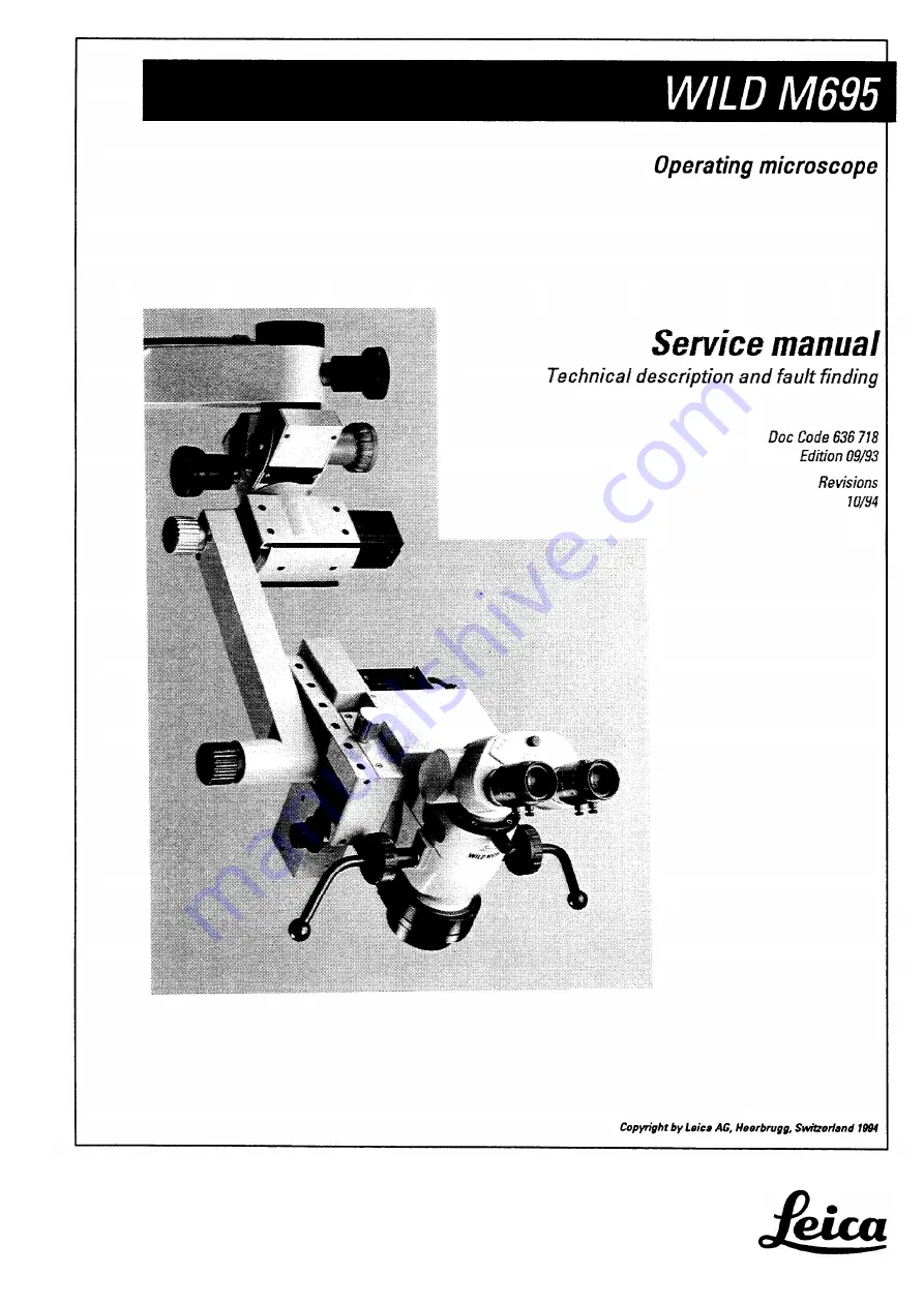
Summary of Contents for WILD M695

Page 1: ...Leica AG CH 9435 Heerbrugg Switzerland Telephone 11 071 70 31 31 Fax 41 071 72 69 52 Leica is a registered trade mark of Leica technologij B V Rijswijk the Netherlands ...

Page 2: ...ction User manual Fault finding with testset Control unit MEL61 62 MEL64 65 5 Swingarm MSV 136 137 6 Microscope M695 7 8 Wiring diagram 9 Replacing modules Replacing boards Inspection procedure 12 13 14 15 16 Training 17 Testset Spare parts catalogue 19 Special tools 20 ...

Page 3: ...Manual M695 Doc Code 636 718 Legal questions Safty Rechtsfragen Sicherheit 09 93 3691 DMF lnhaltsvetzeichnis Table of contents Kapitel Seite Rechtsfragen Legal questions 1 Sicherheit Safety Securite Seguridad 3 ...

Page 4: ...nnen verwendet so lehnt Leica AG Heerbrugg jegliche Haftung ab für direkte und indirekte Schaden die durch nicht fachgemäße Anwendung und oder Interpretation dieses Dokumentes entstehen Copyright Without prior permission in writing by Leica AG Heerbrugg Switzerland this document shall not be reproduced as a whole or in part by mechanical photographic electronic or other means including into or tra...

Page 5: ...rieblichen Unfallverhütungsvorschriften im Wissen dass sich diese auf dem aktuellsten Stand befinden Sie benachrichtigen Leica schriftlich sobald an der Ausrüstung Sicherheitsmangel auftreten Service technicians have the following obligations To understand and follow the safety information and instructions on the product and in the user manual To be familiar with local regulations relating to indu...

Page 6: ...eason for revision M680 control unit MEL61 62 is compatible with M695 Steps to be taken Section Remove page s title sheet index register 2 9 9 1 to 9 8 19 19 1 Number of Introduce page s Number of sheets sheets 1 title sheet 1 1 index register 1 2 1 2 1 4 9 1 to 9 8 4 1 19 1 1 File Insert this sheet Revision in section 2 Leica AG Service Documentation and Training LSG SOM SM ...

Page 7: ...ct the illumination l Engage the shortest working distance the shortest focal length l Engage the lowest zoom position 7 l Inspect the illuminated fields produced by both of the lamps in the lamp changer l If the illuminated area is noticeably restricted readjust the lamps Readjusting the lamp The illumination of the field of view is influenced by the distance between the lamp and the condenser le...

Page 8: ...e moved in the direction of the objective CAUTION The lamp may be hot 3 Switch to the second lamp and carry out point 2 for this lamp 4 Refit the multifocus objective and inspect the illumination as described above 5 If necessary repeat the adjustment procedure points 1 3 Leica AG Service SOM SM W Hammerle ...

Page 9: ...t introduction in March 1994 up to March 1995 the concerned product has been delivered faulty The cement does not withstand the high temperatures at the bulb It has been delivered as a single part as well as included in the following optics carriers M690 optics carrier Mitaka 445 543 M695 optics carrier 445 560 M695 optics carrier Mitaka OH 445 841 Since March 1995 an improved version with the sam...

Page 10: ...1 72 26 77 This is necessary for reasons of product liability Your expenses on this action will be refunded by us via the Repair Report to Factory Please fill out the report completely one report for the complete action Fig 1 The improved second version has approx 5 mm cement free area in the center good improved version where at the old version the whole is completely filled with cement Leica AG ...

Page 11: ...er The covers and instructions for fitting them accompany the control unit From March 1995 onwards only the MEL61 62 control unit will be used for the M680 and M695 The previously used MEL64 65 control unit will no longer be manufactured Modification of the is required if both of the following conditions are met lamp conbol PCB 1 The MEL64 65 control unit is replaced by an MEL61 62 2 The M695 was ...

Page 12: ...Modifications Service manuel WILD M695 10 94 3077 HWE Doc Code 636 718 2 2 ...

Page 13: ... optics carrier You have read the user manual and can operate the surgical microscope Directions are given in Sections 3 and 4 Stage 2 Locating and eliminating errors at module level You have been trained in the basics of electronics and mechanical engineering You have been instructed by a technician from your agency or from LEICA AG HEERBRUGG Sections 3 4 and 10 Stage 3 Locating and eliminating e...

Page 14: ...rtant Section 3 of this manual locating faults with the test set Test box If a fault develops we will guide you to it with the assistance of Section 4 and the test box The test set helps you to assign the fault to the Footswitch Control unit Swingarm Microscope The search is then continued at board level with the assistance of block diagrams and the wiring diagram Control unit MEL64165 Description...

Page 15: ...ins the wiring diagram and a description of the positions of the boards and the plug connections Exchanging modules Section 10 includes instructions for exchanging those modules which are available as spare parts Exchanging boards Testing procedure Test set Spare parts Section 11 includes instructions for exchanging those boards which are available as spare parts After modules or boards have been ...

Page 16: ...ls Section 20 includes a list of the service equipment which will enable you to carry out the operations described above No special tools are required The components making up the test box include a service handswitch and a service cable which serves to bridge the swingann 3 4 ...

Page 17: ...User Manual Service Manual M695 CD ROM 08 98 Doc code 636 718 The M695 User Manual is provided as a separate document To view it click on this text ...

Page 18: ...5 fault finding 09 93 3077 HWE Table of content M695 fault finding Chapter Preparation Power supply of control unit Functions of hand or footswitch Supply of microscope Lamp control Zoom control Focus control Page 4 1 4 3 4 4 4 5 4 7 4 8 4 9 ...

Page 19: ...estbox l Disconnect plug P36 from swingarm l Hook in the testbox to the swingarm and plug in P36 at the testbox l Connect the testbox cable green sleeve with J36 at the swingann With that the control unit is connected with the microscope through the testbox l Set switch MICROSCOPE SELECT on the testbox to position A 4 1 ...

Page 20: ...M695 Fault finding Service manual M695 09 93 3077 HWE Doc code 636 718 2 Settings on the control unit Adjust Lamp to minimal brightness 4 2 ...

Page 21: ... Lamp of main switch does not light Line voltage Fuses F1 and F2 in line plug P1 Main switch S1 Line cable 5V LED on Function Display does not light 24V main supply Transformer Rectifier circuit Wiring 10V supply 5V supply Panel board Receiver board Focus does not move to center position Control unit Swingaxm o r microscope Focus control page 4 9 4 3 ...

Page 22: ...B is disturbed Replace disturbed hand or footswitch ective side A or B by either a Service handswitch or b Hand footswitch at the other CONTROL input Action Reaction Possible reason Release functions Corresponding LED at Function Display does not light Receiver Board Connect again original switch Corresponding LED at Function Hand or footswitch and Display does not light release functions ...

Page 23: ...ax brightness 20V 5 but incorrect lines of 24V and 3 Lamp back to min check PGND brightness page 4 6 Microscope without Wiring of any function microscope Switch off bridge swing arm with servicecable and 26V 5 microscope reacts Swingarm cable switch on again Switch off Separate microscope from 26V 5 Voltage ok evtl short circuit testbox and switch on in the microscope Voltage not ok Control unit 4...

Page 24: ...s ok depending on the incorrect brightness with standard function check signals of swingarm Lamp control page 4 7 cable Zoom control page 4 8 Focus control page 4 9 Bridge swingarm with max 0 8V Voltage ok Swingarm cable service cable and adjust One of the two lamp to max brightness PGND lines is broken Voltage not ok typ 1v One of the two PGND lines in the microscope or control unit is broken Imp...

Page 25: ...n max 0 3V 5V Voltage ok Microscope brightness 5 Lamp Control Wiring Separate microscope from the testbox adjust lamp to min max 0 3V 5V Voltage ok brightness 5 Bridge swingarm with service cable adjust lamp to min max 0 3V 5V Voltage ok brightness 5 Voltage not ok Important Adjust Iamp again to minimal brightness Microscope Swingarm cable Control unit 4 7 ...

Page 26: ...OOM DN footswitch non actuated footswitch non actuated 4 75V 0 2V 4 75v 0 2v Voltages ok but reacts incorrect Microscope Logic board Zoom servo wiring Separate microscope from the testbox and check signals see above Voltages ok Microscope short circuit on Zoom servo or wiring Bridge swingarm with servicecable and verify see above Voltages ok Swingarm cable signals Voltages not ok Control unit 4 8 ...

Page 27: ...ult FOCUS SPEED set min focus speed 1 25 1 27V set max focus speed 5v 5 FOCUS UP FOCUS DN footswitch non actuated 4 75V 0 2V footswitch non actuated 4 75V 0 2V Voltage ok but reacts incorrect Microscope Focus servo wiring Separate microscope from the testbox and check signals see above Voltages ok Microscope short circuit on Focus servo or wiring Bridge swingarm with servicecable and verify see ab...

Page 28: ...M695 Fault finding Service manual M695 09 93 3077 HWE Doc code 636 718 4 10 ...

Page 29: ...695 Description control unit MEL64 65 Doc code 636 718 09 93 3077 HWE Chapter Introduction Power supply Lamp control Zoom control Focus control Description of functions MEL64 65 control unit Page 5 1 5 3 5 9 5 11 5 15 ...

Page 30: ...n the control unit and partly in the microscope itself Their functions are described in the following sections 5 and 7 The swingarm cable is the electrical link between the control unit and the microscope and is therefore the ideal place to start looking for faults at the level of the main groups The test box is introduced between the swingarm and the microscope It can be used to study the supply ...

Page 31: ...Description of control unit MEL64 65 Service manual M695 09 93 3077 HWE Doc code 636 718 Notes ...

Page 32: ... gear Control elements displays Pages Red LED on panel board indicates defective fuse 5 6 Green LED on panel board shows 10V O K 5V supply for logics of receiver board and foots witch or handswitch LED 5V OK on function display Ground PGND Microscope ground SENS GND_XY XY ground Yellow LED on panel board indicates switch off caused by excess current Logics ground microscope 5 6 5 7 5 7 5 7 ...

Page 33: ...Description of control unit MEL64 65 Service manual M695 09 93 3077 HWE Doc code 636 718 ...

Page 34: ...Service manual M695 Doc code 639 718 Description of control unit MEL64 65 09 93 3077 HWE ...

Page 35: ...powers the servo board via the receiver board and the microscope via the swingann The fuse for the unstabilized main supply voltage is on the panel board 6 3AT The red LED indicates a burnt fuse The loading at maximum lamp brightness is about 3 25A The yellow LED on the panel board indicates switching off as a result of excess current 5A at PGND A switching regulator on the panel board reduces the...

Page 36: ...nd PGND and SENS are connected in the microscope The high lamp current produces a voltage drop of about 0 6V at PGND This voltage is passed to the control unit through SENS SENS For the reason indicated above Logic ground is about 0 6V below PGND in the microscope The voltage drop at PGND influences the level of the control signals All control signals to the microscope are measured with the testbo...

Page 37: ...Description of control unit MEL64 65 Service manual M695 09 93 3077 HWE Doc code 636 718 Notes ...

Page 38: ...n of control unit MEL64 65 09 93 3077 HWE Lamp control MEL64 65 Tasks Setting the lamp brightness Limiting excess current Control element display Pages Potentiometer on control unit 5 10 7 3 Measurement resistor on LAMP CONTROL in microscope 7 3 5 9 ...

Page 39: ...erence for lamp regulator The voltage level LAMP REF depends on the position of the brightness potentiometer LAMP REF is passed via the receiver board and the swingarm cable to the lamp control board in the microscope where it forms the reference value required value of the lamp regulator 5 10 ...

Page 40: ... MEL64 65 DOc code 636 718 09 93 3077 HWE Using motor to set zoom position Presenting zoom adjustment speed Control elements display Footswitch or handswitch Function display Up down LED on zoom servo Zoom speed potentiometer 5 14 7 6 5 14 7 8 5 11 ...

Page 41: ...Description of control unit MEL64 65 Service manual M695 09 93 3077 HWE Doc code 636 718 5 12 ...

Page 42: ...Service manual M695 Doc code 636 718 Description of control unit MEL64 65 09 93 3077 HWE 5 13 ...

Page 43: ...m position correspond to the functions Data format ASCII 8 bit with start bit repeating at 2 3 millisecond intervals 5W 8V The logics on the receiver board processor assign the codes received to their appropriate functions ZOOM UP ZOOM DOWN The control signals 0V 5V for ZOOM UP and ZOOM DOWN reach the logics board in the microscope via the swingarm cable Presetting the zoom displacement speed The ...

Page 44: ...ized focusing Presetting speed of focusing Travelling to centre position after switching on or resetting Control elements display Footswitch or handswitch Functiondisplay Up down LED on focus servo Focus speed potentiometer Footswitch or handswitch Reset switch on motor driven objectiv MOBxxx Pages 5 18 7 5 18 7 5 19 7 5 15 ...

Page 45: ...Description of control unit MEL64 65 Service manual M695 03 93 3077 HVVE Doc code 636 718 5 16 ...

Page 46: ...Service manual M695 Description of control unit MEL64 65 Doc code 636 718 09 93 3077 HWE 5 17 ...

Page 47: ...functions Data format ASCII 8 bit with start bit repeating at 2 3 millisecond intervals 5V 8V The logics on the receiver board processor assign the received codes to their appropriate functions FOCUS UP FOCUS DOWN CENTER POSITION The control signals 0V 5V for FOCUS UP and FOCUS DOWN reach the logics board in the microscope via the swingarm cable Presetting the focusing displacement speed The volta...

Page 48: ...on This function is activated from the handswitches or footswitches A and B using the key SL A timer Monoflop sets FOCUS SPEED to GND potential for about 30 milliseconds using a transistor The impulse is recognized on the focus servo in the motor driven objectiv MOBxxx and the system is steered to the mid position ...

Page 49: ...Description of control unit MEL64 65 Service manual M695 09 93 3077 HWE Doc code 636 718 Notes 5 20 ...

Page 50: ...Service manual M695 Description swingarm MSV136 137 Doc code 636 718 09 93 3077 HWE Chapter Power supply Microscope control Table of content List of signals for swingarm MSV136 137 Page 6 1 6 3 ...

Page 51: ...ed are only valid under these conditions Power supply SIGNAL Voltage against PGND Lamp min brightness Voltage against PGND Lamp max brightness Voltage against SENSE Lamp min brightness Voltage against SENSE Lamp max brightness Voltage drop against logics level Lamp min brightness Test box Microscope Setting Focus up Voltage drop against logics level Lamp max brightness Test box Microscope Setting ...

Page 52: ...on swingarm MSV136 137 Service manual M695 09 93 3077 HWE Doc code 636 718 Current consumption Microscope Lamp min brightness Quick change lamp mount disengaged 150mA 50mA Lamp max brightness Guiding value 3 5A ...

Page 53: ...inst SENSE Unless otherwise indicated set the lamp to minimum brightness SIGNAL CONDITIONS LAMP REF Lamp min max brightness FOCUS SPEED FOCUS UP FOCUS DN ZOOM SPEED ZOOM UP B ZOOM DN Min Max Low High Low High min max Low High Low High VALUE 0 3 5V TOL 5 1 25 1 7V 5V 5 0 2V 4 75V 0 2V 4 75V 1 84 2 34V 5V 5 0 2V 4 75V 0 2V 4 75V 6 3 ...

Page 54: ...Description swingarm MSV136 137 Service manual M695 09 93 3077 HWE Doc code 636 718 6 4 ...

Page 55: ...anual M695 Description microscope M695 Doc code 636 718 09 93 3077 HWE Chapter Power supply Lamp control Zoom control Focus control Table of content Description of functions M695 microscope Page 7 l 7 3 7 5 7 9 ...

Page 56: ...vice manual M695 Doc code 636 718 Description microscope M695 09 93 3077 HWE Power Supply M695 microscope For functions of control unit refer to page 5 3 Tasks Page 24V Supply 7 2 Ground PGND SENS 7 2 7 1 ...

Page 57: ...e The high lamp current causes a voltage drop of about 0 6V to PGND This voltage is passed to the control unit through SENS For the reason indicated above Logics Ground is about 0 6V below PGND in the microscope The voltage drop at PGND affects the level of the control signals and so longer swingarm cables than the standard ones can result in malfunctioning New situation as from August 1993 Logics...

Page 58: ...roscope M695 09 93 3077 HWE Lamp control M695 microscope For functions of control unit refer to page 5 9 Tasks Control elements displays Setting the lamp brightness Control unit Limiting the excess current Measuring resistor on LAMP CONTROL Page 7 4 7 4 ...

Page 59: ...he final stage transistors The voltage is smoothed with chokes and electrolytic condensers and the electricity is conducted to the lamp The secondary voltage is compared with the required value LAMP REF at the entrance of the regulator The lamp current produces a voltage drop across resistor R9 in Lamp Ground LGND The regulator measures this voltage drop and limits the current to 5A during the fin...

Page 60: ...oom control M695 microscope For functions of control unit refer to page 5 11 Tasks Setting zoom position with motor Recognizing end of range Presetting zoom displacement speed Control elements displays LEDs ZOOM UP DOWN Light barriers on ZOOM SERVO Control unit Page 7 6 7 7 7 8 7 5 ...

Page 61: ...om position The control signals 0V 5V for ZOOM UP and DOWN reach the zoom board via the swingarm cable and lamp control board in the microscope ZOOM UP DOWN activates the final stage transistors on the zoom servo board The end stage comprises a bridging circuit of transistors In accordance with the direction of displacement the transistors are activated by two T1 and T3 or T2 and T4 ...

Page 62: ... is marking the limit area It is sensed by two light barriers located on the zoom servo If one of both light barriers senses the white field through a gate the transistor bridge is blocked for that direction of displacement Before removing the encoder disk Mark the disks position at its flange The adjustment of the disk is described in section 11 Replacing boards Zoom servo ...

Page 63: ...djusted by means of the supply voltage for the zoom motor The final stage only has a switching function The ZOOM SPEED level is the reference for the voltage regulator on the zoom servo board The regulator has a positive current feedback and so the motor voltage increases with the load The current through the final stage is limited to about 150mA ...

Page 64: ...pe For functions of control unit refer to page 5 15 Tasks Motorized focusing Recognizing end of range Light barriers on FOCUS SERVO Presetting the focus displacement speed Control unit Travelling to the mid polnt Control unit Focus reset switch Control unit Control elements displays Page 7 12 7 12 7 12 7 12 ...

Page 65: ...Description microscope M695 Service manual M695 09 93 3077 HWE Doc code 636 718 ...

Page 66: ...Service manual M695 Description microscope M695 Doc code 636 718 09 93 3077 HWE 7 11 ...

Page 67: ...he displacement speed is altered with the supply voltage for the focus motors The final stage only has a switching function The FOCUS SPEED level is the reference for the voltage regulator on the focus servo board The current through the final stage is limited to about 140mA Travelling to the mid position Triggered by Pressing key Center Position at the focusing unit Switching on the microscope 30...

Page 68: ... J17 9 4 9 5 9 6 JP18 9 7 J19 9 4 9 5 9 6 P19 9 8 JP20 9 10 JP21 9 10 JP22 9 10 Einheit Unit Steuergerät Control unit MEL64 65 Steuergerät Control unit MEL64 65 Steuergerät Control unit MEL64 65 Steuergerät Control unit MEL64 65 Steuergerät Control unit MEL64 65 Steuergerät Control unit ME L64 65 Steuergerät Control unit MEL64 65 Steuergerät Control unit MEL64 65 Steuergerät Control unit MEL64 65 ...

Page 69: ...P30 9 11 J32 9 12 P32 JP33 J36 P36 J37 9 10 9 12 9 9 9 10 9 9 Mikroskop Microscope M695 Mikroskop Microscope M695 Mikroskop Microscope M695 Steuergerät Control unit MEL64 65 Mikroskop Microscope M695 Mikroskop Microscope M695 Mikroskop Microscope M695 Mikroskop Microscope M695 Schwenkarm Swingam MSV136 137 Mikroskop Microscope M695 Schwenkarm Swingarm MSV136 137 ...

Page 70: ...s Board Seite Page Einheit Unit Focus Servo 9 12 Function Display 9 6 Lamp Control 9 10 Panel Board 9 7 Receiver Board 9 6 Zoom Servo 9 11 XY Servo Board 9 6 Mikroskop Microscope M695 Steuergerät Control unit MEL61 62 MEL64 65 Mikroskop Microscope M695 Steuergerät Control unit MEL61 62 MEL64 65 Steuergerät Control unit MEL61 62 MEL64 65 Mikroskop Microscope M695 Steuergerät MEL61 62 Control unit M...

Page 71: ...Verdrahtung Wiring Service Manual M695 10 94 3077 HWE Doc Code 636 718 Steuergerät MEL61 62 Anschlussplatte Control unit MEL61 62 Connector panel ...

Page 72: ...Service Manual M695 Verdrahtung Wiring Doc Code 636 718 10 94 3077 HWE Steuergerät MEL64 65 Anschlussplatte Control mit MEL64 65 Connector panel ...

Page 73: ...Verdrahtung Wiring Service Manual M695 10 94 3077 HWE Doc Code 636 718 Steuergerät MEL61 62 und MEL64 65 Rückwand Control unit MEL61 62 and MEL64 65 Rear section ...

Page 74: ...Service Manual M695 Verdrahtung Wiring Doc Code 636 718 10 94 3077 HWE Steuergerät MEL61 62 und MEL64 65 Front Control unit MEL61 62 and MEL64 65 Front section ...

Page 75: ...Verdrahtung Wiring Service Manual M695 09 93 3077 HWE Doc Code 636 718 Schwenkarmkabel Stecker zum Steuergerät Swing arm cable Connector to control unit ...

Page 76: ...Service Manual M695 Doc Code 636 718 Verdrahtung Wiring 09 93 3077 HWE Schwenkarmkabel Stecker zum Mikroskop M695 Swing arm cable Connector to microscope M695 ...

Page 77: ...Verdrahtung Wiring 09 93 3077 HWE Service Manual M695 Doc Code 636 718 Mikroskop M695 Ansicht auf U Träger Microscope M695 View to U carrier ...

Page 78: ...Service Manual M695 Verdrahtung Wiring Doc Code 636 718 09 93 3077 HWE Mikroskop M680 Ansicht auf Zoom Servo Microscope M680 View to zoom servo ...

Page 79: ...Verdrahtung Wiring Service Manual M695 09 93 3077 HWE Doc code 636 718 Mikroskop M695 Ansicht auf motorische Fokussierung MOB Microscope M695 View motorized focusing MOB ...

Page 80: ......

Page 81: ...Service Manual M695 Replacing modules Doc Code 636 718 09 93 3691 DMF Contents Replace X Y slide Replace gas spring of swingarm Replacing swingarm cable Page 10 1 10 2 10 5 ...

Page 82: ...rvice Manual M695 Replacing modules Doc Code 636 718 09 93 3691 DMF Replace X Y slide Remove 2 screws 1 and cover 2 Remove 6 hollow screws 3 and X Y slide 4 After each manipulation inspect the functioning ...

Page 83: ... Doc Code 636 718 Replace gas spring of swingarm MSV136 137 Set counterbalance to 10 Remove 2 screws 1 and parallel bar 2 Remove washer 3 and parking piece 4 Note The hole to hole distance of the parallel bar can be set by turning the eccentric sleeve 5 ...

Page 84: ...Manual M695 Doc Code 636 718 Replacing modules 09 93 3691 DMF Release screw 1 disengage safety hook 2 Pull swingarm down until spindle 3 and screw 4 are tension free Remove spindle 3 screw 4 and parallel bar 5 ...

Page 85: ...8 Remove spacer ring 1 safety ring 2 and pin 3 Assembly Fit pin 3 with longer end towards safety hook Assembly Screw gas spring fully in and then unscrew by up to turn until swingarm bearing and gas spring bearing coincide Remove gas spring 4 from mount 5 and unscrew it ...

Page 86: ...mplete with Lemo plug Open AMP plug and push contact pins out to the rear Pull cable out from swingarm Note Tie a 1 5 metre long string to the cable so that it is easier to pull in Assembly Bundle together the contact pins of the new cable and bind them with adhesive tape Raise the swingarm to its highest position and pull in the cable Secure cable duct 3 with a cable tie one metre away from the A...

Page 87: ......

Page 88: ... boards Doc Code 636 718 09 93 3691 DMF Contents Motorized focusing Focus servo board M695 Replace lamp control board Control unit Replacing panel board Replacing receiver board Replacing display board Page 11 1 11 2 11 3 11 4 11 4 ...

Page 89: ... boards 09 93 3691 DMF Motorized focusing Focus servo board for motorized focusing Remove 6 screws 1 adapter 2 and upper part of housing 3 Remove 6 screws 4 Raise focus servo board 5 Pull out plug J33 After each manipulation inspect the functioning ...

Page 90: ...3691 DMF Service Manual M695 Doc Code 636 718 M695 optics carrier Replace lamp control board Remove 3 screws 1 and bracket 2 Pull out 4 plugs 3 Remove 2 countersunk screws 4 2 cheese head screws 5 and the lamp control board 6 ...

Page 91: ...65 Replacing panel board Remove 4 screws with washers 1 Remove knob cover 2 and knobs 3 Open front cover 4 Pull out 2 plugs Unscrew and remove 4 screws 5 Remove panel board 6 Assembly The maximum permissible gap between knobs and front cover is 0 5mm Adjust the rotation range of the knobs ...

Page 92: ...695 Doc Code 636 718 Replacing receiver board Remove spacer nut 1 Pull plug out from receiver board 2 Remove receiver board Replacing display board Remove 2 screws with washers 3 and take out function display 4 Assembly Align LEDs with display window ...

Page 93: ...636 718 09 93 3691 DMF Contents Section 1 Inspecting the hand footswitch functions and function display on the MEL64 65 2 Lamp control 3 ZOOM control 4 FOCUS control 5 Optics 6 Tiltable joint swingarm Test report Page 12 l 12 4 12 4 12 5 12 6 12 6 12 7 ...

Page 94: ...itch 6 functions and the power plug to the MEL 64 65 The plugs must go in and out without difficulty 1 2 Activate the power switch of the MEL64 65 The control unit switches on and the indicator lamp in the power switch shines The 5V LED on the function display shines The ML LED on the function display shines If the control unit does not switch on Inspect the power cable and the power connection In...

Page 95: ...e the foot or handswitch and repeat the inspection procedure If there is still a fault then its source is to be found in the MEL64 65 control unit Fault location in hand footswitch functions page 4 4 ML on off Microscope lamp M L A on off Additional illumination Focus up Focus down Zoom up Zoom down A 1 4 Connect cables of microscope and swingarm The plugs must go in and out without difficulty ...

Page 96: ... procedure 09 93 3691 DMF Preparation Connect test box Separate plug connection J P36 on swingarm Hang test box on to swingarm Connect plug P36 from test box to swingarm and from M695 microscope to test box Set test box switch MICROSCOPE SELECT to A ...

Page 97: ...prings out Push the orange indicator back into the rear wall Fault location in lamp control page 4 7 3 1 Turn the ZOOM SPEED potentiometer from min to max and from max to min Reading on test box ZOOM SPEED min max 1 84 2 34Vl5V 5 The zoom speed is continuously adjustable 3 2 Use foot handswitch to activate ZOOM UP Reading on test box ZOOM UP Low High 0 2V 4 75V 3 3 Use foot handswitch to activate ...

Page 98: ...in Reading on test box FOCUS SPEED min max 1 25 1 7V 5V 5 The focus speed is continuously adjustable Use foot handswitch to FOCUS UP Reading on test box FOCUS UP Use foot handswitch to FOCUS DN Low High 0 2V 4 75V Reading on test box FOCUS DN Fault location in FOCUS control page 4 9 Mechanical focus movement Focus moves uniformly in both directions Activate yellow knob on motorized focusing FOCUS ...

Page 99: ...er the brake has been released Brakes As the braking knob is applied the movement becomes steadily less free and finally the joint locks completely When the brake knob is turned the other way the movement steadily becomes easier Clip on handles The sterilizable clip on handles must be convenient to put on and take off again They must click in and out perfectly Gas spring The vertical adjustment mu...

Page 100: ... carrier 45 445 562 Microscope carrier 45 70 445 494 Swingarm MSV136 for floor stand 445 740 Swingarm MSV167 for ceiling mount 445 551 Control unit MEL64 for floor stand 445 552 Control unit MEL65 for ceiling mount 445 365 Objective mot foe f 250mm 445 563 Objective mot foe f 325mm 445 564 Objective mot foe f 275mm Footswitch 6 functions 445 203 Handswitch 12 functionsn Binocular tube MTU Other ac...

Page 101: ...Prüfprotokoll 09 93 3691 DMF Service Manual M695 Doc Code 636 718 Test report for M695 ...

Page 102: ...the instrument ready for use use the test box to locate faults exchange modules and boards in accordance with the instructions carry out a comprehensive inspection of the functions Leica AG Heerbrugg Service LSG MSM training department In agencies provided that the service technician instructor has alredy attended an M695 course at Leica AG in Heerbrugg 2 days In accordance with present guidelines...

Page 103: ...he swingarm and the microscope Plug connections JP36 and JP37 2 Inspect the voltages and currents of the POWER SUPPLY as described in Section 4 3 Substitute service handswitch for footswitch observe signal voltages and also monitor LEDs on control unit 4 Observe the signal voltages of the defective function MICROSCOPE CONTROL or XY gear as described in Section 4 Cause in microscope of in XY gear 5...

Page 104: ...D such to the XY gear relative to GND_XY measure at low light level Unless otherwise indicated set the lamp to minimum brightness The voltages indicated in Section 4 are only valid for this condition Voltage levels are falsfied by the voltage drop between the control unit and the microscope Because of the current taken by the lamp this voltage drop to PGND measuring ground can be as much as 0 9V T...

Page 105: ...hree galvanically separating DC converters each reduce the voltage to approx 12V each Rotary switch S1 Displaces the decimal point on the display by one digit to the right for the 24V measuring ranges POWER SUPPLY Diagram on page 18 6 Rotary switch S1 Voltage distributor Level 1 Selects current and voltage ranges 1 10 for 12V range 1 100 for 24V ranges Current measurement range Voltage drop across...

Page 106: ...WE Doc code 636 718 XY GEAR at M680 only Diagram on page 18 8 Rotary switch S4 Voltage distributor Measuring ground Specifications Selects the signals from and to XY GEAR 1 10 GND_XY Voltage measurement Current measurement 3 1 digit 5 1 digit ...

Page 107: ...Service Manual M695 Testset Doc code 636 718 09 93 3077 HWE ...

Page 108: ......

Page 109: ......

Page 110: ......

Page 111: ......

Page 112: ...Testset Service Manual M695 09 93 3077 HWE Doc code 636 718 ...

Page 113: ...e delivered since martch 94 If the lamp control board does not have index C of modification or later it must be modified as shown on page 2 1 Else the following fault occurs the hand footswitch at control input B does not react 433 826 Gas spring See page 10 4 507 990 Focus servo board See page 11 1 526 770 Function display Seepage 11 4 561 950 Panel hoard für MEL64 65 Seepage 11 3 567 930 635 859...

Page 114: ...Ersatzteilkatalog Spare parts catalogue 10 94 3691 DMF Doc Code 636 718 Art Nr Stock n Benennung Spezifikation Description Specification Bemerkung Remark Zeichnung Drawing ...

Page 115: ...Service Manual M695 Doc Code 636 718 Special tools 09 93 3691 DMF 401 283 Pin spanner 418 135 Handle for pin spanner 566 152 Test set compl without boards 566 146 Test box 566 147 Hand switch mod ...

Page 116: ...Special tools Service Manual M695 09 93 3691 DMF Doc Code 636 718 556 148 Service cable M680 M695 566 151 Box ...

Reviews: