background image

Page 1

 1998 Lennox Industries Inc.

Litho U.S.A.

Corp. 9804-L4

O24/OF24

Service Literature

O24 / OF24 SERIES UNITS

O24 (Elite 80

) series units are heating only mid-efficiency

upflow oil furnaces manufactured with Beckett oil burners.
O24 units are available in heating capacities of 70,000 to
154,000 Btuh (20.5 to 45.1 kW). O24 units are suitable for resi
dential or commercial applications. 
OF24 (Elite 80) series units are heating only mid-efficiency lo-
boy up-flow furnaces, which cime in front (OF24) or rear
(OF24R) flue openings. Both furnaces use Beckett oil burners
with heating capacities of 105,000 to 154,000 Btuh (30.8 kW to
45.1 kW). OF24 units are suitable for residential or commercial
application.    
The drum type heat exchanger comes with strategically
placed ports allowing easy cleaning. The oil burner can be
easily removed for inspection and service. The mainte
nance section gives a detailed description on how this is
done.
Information contained in this manual is intended for use by
experienced HVAC service technicians only. All specifica
tions are subject to change. Procedures outlined in this
manual are presented as a recommendation only and do not
supersede or replace local or state codes.

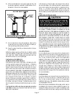
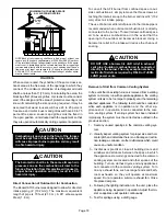
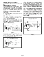
O24 UPFLOW

OF24 

REAR FLUE

 MODEL

OF24

FRONT FLUE

MODEL

Summary of Contents for Elite 80 Series

Page 1: ...furnaces use Beckett oil burners with heating capacities of 105 000 to 154 000 Btuh 30 8 kW to 45 1 kW OF24 units are suitable for residential or commercial application The drum type heat exchanger co...

Page 2: ...203 12 x 9 305 x 229 Blower Data Blower pulley in mm 7 178 Belt size in mm 40 1016 41 1041 cfm L s at 20 in wg 50 Pa external static pressure 820 390 1170 550 1550 730 Number and size of filters in mm...

Page 3: ...in mm 10 x 8 254 x 203 12 x 9 305 x 229 Blower Data Blower pulley in mm 7 178 Belt size in mm 41 1041 42 1067 cfm L s at 20 in wg 50 Pa external static pressure 1300 615 105 input 1220 575 120 input...

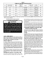
Page 4: ...URNER INDOOR BLOWER BLOWER MOTOR OBSERVATION PORT CLEAN OUT PORT FLUE OPENING HEAT EXCHANGER COMBUSTION AIR INTAKE FIGURE 2 OF24 GENERAL PARTS ORIENTA TION CLEAN OUT PORT FAN LIMIT SWITCH BECKETT AFII...

Page 5: ...identifies the burners used in Lennox units Figure 3 shows the typical layout of the burner assembly 1 Combustion Air Blower Pump Motor B6 The burner is activated by the primary control A com bustion...

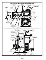
Page 6: ...OZZLE AIR SCOOP INLET WHEEL BLOWER FLANGE GASKET DOOR GASKET REAR ACCESS COUPLING OIL PUMP PLATE ESCUTCHEON NUT SPLINED DOOR ASSY REAR ACCESS ASSY HOUSING MAIN HOLE PLUG SCREWS AIR TUBE FLANGE ASSY EL...

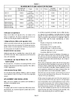
Page 7: ...in the O24 OF24 The firing rate dictates which head is used See table 1 The greater the FB number the larger the slots on the head When combustion takes place the flame will be cylindrical compact sha...

Page 8: ...an air free fuel to the burner An oil filter is required for all models Use an oil filter of gener ous capacity for all installations Install filter inside the building between the tank shut off valve...

Page 9: ...g g Single Stage Two Stage Single Stage Two Stage 0 0 0 m 84 25 6 m 93 28 3 m 100 30 5 m 100 30 5 m 2 0 6 m 73 22 3 m 85 25 9 m 100 30 5 m 100 30 5 m 4 1 2m 63 19 2 m 77 23 5 m 100 30 5 m 100 30 5 m 6...

Page 10: ...not pass through a floor or ceiling Clear ances to single wall vent pipe should be no less than 6 152 mm more if local codes require it 8 The vent may pass through a wall where provisions have been m...

Page 11: ...rements for exhaust vents and oil piping Combustion Air Requirements CAUTION Insufficient combustion air can cause headaches nausea dizziness or asphyxiation It will also cause excess water in the hea...

Page 12: ...tilation the confined space shall be provided with two permanent openings One opening shall be within 12 305 mm of the top of the enclosure and one within 12 305 mm of the bottom These openings must...

Page 13: ...from confined space to out side combustion air simply remove the three screws at taching the inlet air scoop to the burner and insert 4 102 mm direct air intake piping The use of a barometric relief p...

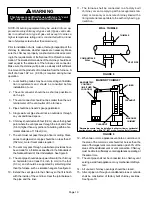
Page 14: ...be located within 18 457 mm of the furnace vent outlet See figure 15 for barometric draft con trol location III START UP A Preliminary and Seasonal Checks 1 Inspect electrical wiring both field and f...

Page 15: ...inimum FIGURE 16 AFII ELECTRODE TIP GAP To position the electrode tips beyond the face of the nozzle and above the center line position the gauge as shown in figure 17 Align the center mark with the n...

Page 16: ...retention head burners Oil furnace installations also require careful inspection to make sure the chimney is in good condition and can ac commodate the products of combustion The temperature in uncon...

Page 17: ...mbly will come out of the furnace There is adequate wire to remove the burner without disconnecting wires Once removed just turn the burner around in the vest panel area NOTE Before disassembling any...

Page 18: ...rom the primary control If the motor and blower wheel only need to be removed to check and clean there is adequate wire in the motor wiring harness without disconnecting 3 Loosen two bolts securing mo...

Page 19: ...atmosphere 3 With only the blower motor running and the evapora tor coil dry observe the manometer reading Adjust blower motor speed to deliver the air desired accord ing to the job requirements 4 Pr...

Page 20: ...as described in section IV D Supply Air Blower 1 Disconnect power to unit 2 Check and clean blower wheel 3 Motors are prelubricated for extended life no further lu brication is required E Vent Pipe Th...

Page 21: ...close energizing combustion air blower pump B6 3 When 1K2 closes the electronic ignitor is energized When 1K1 closes the solid state switch and cad cell are energized When the cad cell senses light t...

Page 22: ...NCE 1 When 1K2 closes 120VAC is routed through the relay timer electronic ignitor A73 and the limit switch 2 The relay timer energizes the venter motor 3 After the venter motor establishes a draft the...

Page 23: ...RATION SEQUENCE 1 When 1K2 closes 120VAC is routed through the relay 2 The relay energizes the venter motor 3 After the venter motor establishes a draft the N O fan proving switch closes completing th...

Page 24: ...lution Close all leaks with cement Problem Failure to extend the length of the flue partition down to the floor Detected by inspection or smoke test Solution Extend partition to floor level Problem Sm...

Page 25: ...r leak around cover Be sure strainer cover screws are tightened securely Check for damaged cover gasket To determine the cause of improper cutoff insert a pressure gauge in the nozzle port of the fuel...

Page 26: ...r auxiliary control switch open Open circuit between disconnect switch and limit control Low line voltage or power failure Defective internal control circuit Jumper terminals if burner starts switch i...

Page 27: ...ll power company Properly ground transformer case Check voltage at power source Correct cause of voltage drop or call power company Motor does not come up to speed and trips out on overload Turn off p...

Page 28: ...hermostat in warm air draft Dirty furnace air filters Blower running too slow Blower motor seized or burned out Blower wheel in backwards Wrong motor rotation Restrictions in return or supply air syst...

Reviews: