
J
'J
t
Whitfield
T�tTIONS
rNSTALLATION
INSTRUCTIONS
FREESTANDING AND INSERT
PELLET FIRED Sl'OVES
LISTED ROOM HEATER, PELLETIZED WOOD FUEL TYPE
P/N20922000, REV. A, 11/2000
/
,
MODELS
P11, Profile 20 & Profile 30 /
r,1
1
1"
V �,•,
I
::::.
f
·
=
'
=
=
·
=· ===-'
i
Ii
I
n:
---
-
·-
--
·--.
--�-'
-
�
-
l
II
I
}
0
t
.
--*-
�-�
..
�
--
7
.
=�
'
II
�,·
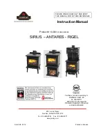
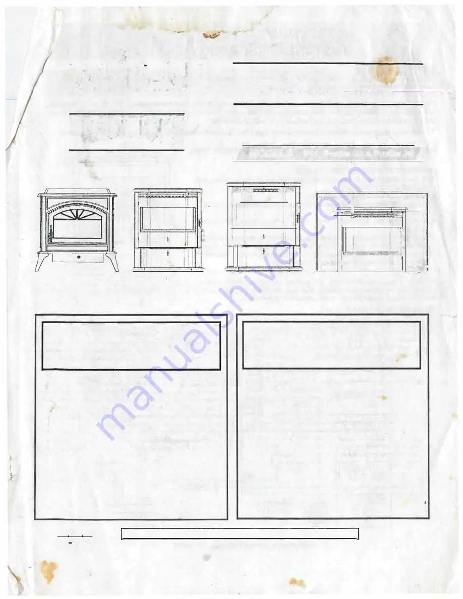
Traditions
™
Freestanding Whitfield
™
Freestanding Whitfield
™
Freestanding
Whitfield
™
Insert
Model Profile 30
Model P11
Model Profile 20
Model Profile 30
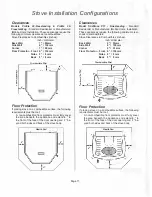
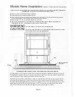
Warning: The minimum clearances specified must
be maintained for all combustible surfaces and
materials including: furniture, capet, drapes, ·cloth
ing, wood, papers, etc. Do not store pellet fuel
within this clearance zone.
These stoves must be properly installed and oper
ated in order to prevent the possibility 'of a house
fire. Please read this entire owl'}er's manual before
insiamng and using your Whitfield-or Traditions
pefflet stove. Failure to follow these instructions
could result in property damage, bodily injury or
even death. Contact your local building or fire offi
cials to obtain a permit and information on any
installation restrictions and inspection requirements
in your area.
Do not use class B venting intended for gas
appliances as a chimney or connector pipe on a
pellet fired appliance.
Do not connect this appliance to a chimney flue
connected to another appliance.
Warnock Hersey
Burning any kind of fuel consumes oxygen.
If outside air is not ducted to the appliance,
ensure that there is an adequate source of fresh
air available to the room where the appliance
is installed.
FOR YOUR SAFETY: Do not store or use gasoline or
other flammable vapors or liquids in the vicinity of
this or any other appliance.
Manufactured (mobile) home requirements: An out
side air inlet must be provide9 for combustion and
be unrestricted while unit is in use. Do not install
appliance in a sleeping room. The structural integ
rity of the manufactured home floor, walls, ceiling
and roof must be maintained. Regulations require
that the appliance must be secured to the floor and
grounded to the chassis.
This appliance requires non-combustible floor
protection or approved hearth/hearth protection as
specified in this manual.
,-,
WH Report Numbers: Traditions P11: 476-1129, Profile 20: 476-6658, Profile 30: 476-1244
C
■ ■
®
■
US
Page 1
i,
l
Serial # up to 5492