


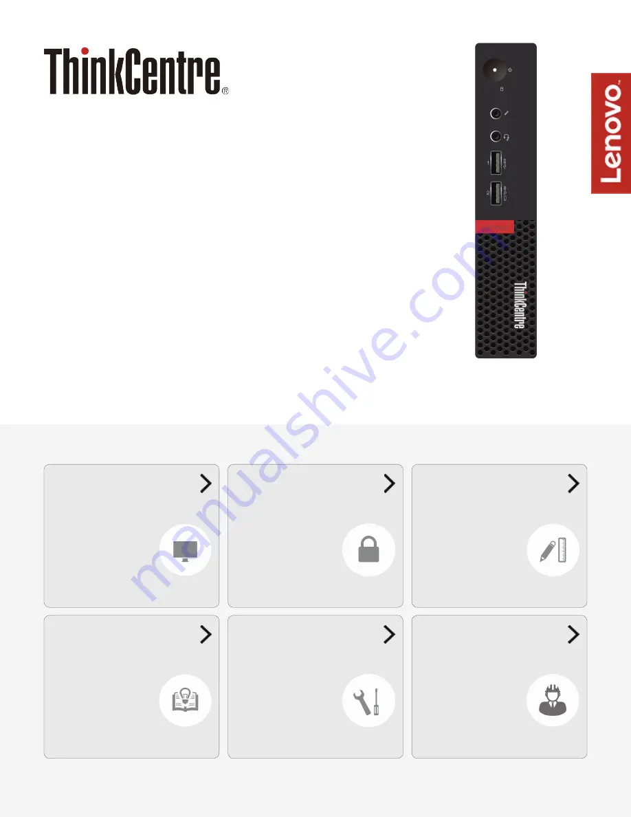
M910q
User Guide and
Hardware Maintenance Manual
Machine Type (MT):
10MU, 10MV, 10MW, 10MX, 10QN
Energy Star MT:
10MU, 10MV, 10MW, 10MX, 10QN
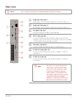
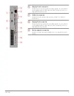
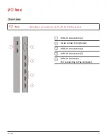
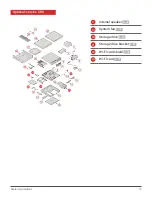
Locations of indicators,
connectors, and
controls provided on
your computer
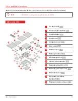
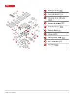
Locations of the
replaceable parts on
your computer
units (FRUs) (for
technicians only)