background image

506305-01

Page  1  of  36

Issue 0938

Save these instructions for future reference

TABLE OF CONTENTS

SAFETY ............................................................... 2

INSTALLATION .................................................... 3

START-UP .......................................................... 26

OPERATION ...................................................... 27

MAINTENANCE ................................................. 30

REPAIR PARTS .................................................. 31

CONTROL SYSTEM DIAGNOSTICS ................. 32

WIRING DIAGRAMS .......................................... 33

INSTALLATION INSTRUCTIONS

G1D91BU, G1D91BT, G1D93BU, G1D93BT & G1D93BC

High Efficiency 90+ Condensing Gas Furnace

With System Sentry™ Control System

Manufactured By

Allied Air Enterprises Inc.

A Lennox International Inc. Company

215 Metropolitan Drive

West Columbia, SC 29170

*506305-01*

The installation of the furnace, wiring, warm air ducts, venting, etc. must conform to the requirements of the National Fire
Protection Association; the National Fuel Gas Code, ANSI Z223.1/NFPA No. 54 (latest edition) and the National Electrical
Code, ANSI/NFPA No. 70 (latest edition) in the United States; CSA B149.1 (latest edition) Natural Gas and Propane Installation
Codes and the Canadian Electrical Code Part 1, CSA 22.1 (latest edition) in Canada; and any state or provincial laws, local
ordinances (including plumbing or wastewater codes), or local gas utility requirements.  Local authorities having jurisdiction
should be consulted before installation is made.  Such applicable regulations or requirements take precedence over the general
instructions in this manual.


WARNING

This furnace is not approved for installation in a mobile
home.  Do not install this furnace in a mobile home.
Installation in a mobile home could result in actions that
could cause property damage, personal injury, or death.


WARNING

Do not store combustible materials, including gasoline and
other flammable vapors and liquids, near the furnace, vent
pipe, or warm air ducts.  The homeowner should be
cautioned that the furnace area must not be used as a
broom closet or for any other storage purposes.  Such uses
may result in actions that could cause property damage,
personal injury, or death.


WARNING

Improper installation, adjustment, alteration, service, or maintenance can cause injury or property damage.
Refer to this manual.  For assistance or additional information, consult a qualified installer, service
agency, or the gas supplier.


WARNING

Summary of Contents for G1D91BT

Page 1: ...a and any state or provincial laws local ordinances including plumbing or wastewater codes or local gas utility requirements Local authorities having jurisdiction should be consulted before installation is made Such applicable regulations or requirements take precedence over the general instructions in this manual WARNING This furnace is not approved for installation in a mobile home Do not instal...

Page 2: ...ping beginning on page 22 of these instructions IMPORTANT SAFETY INFORMATION 7 Always install furnace to operate within the furnace s intended temperature rise range with a duct system which has an external static pressure within the allowable range as specified in Temperature Rise on page 28 of these instructions See furnace rating plate 8 When a furnace is installed so that the supply ducts carr...

Page 3: ...ment of another appliance such as a water heater Agas fired furnace for installation in a residential garage must be installed so the burner s and the ignition source are located not less than 18 above the floor The furnace is to be located or protected to avoid physical damage by vehicles This furnace is not recommended to be used as a construction heater during any phase of construction Very low...

Page 4: ...st be kept free and clear of insulating materials Clearances All servicing and cleaning of the furnace can be performed from the front If installed in a closet or utility room provide 18 clearance in front for service if the door to the room is not in line with the front of the furnace Refer to Table 1 for the minimum clearances to combustibles required for construction and proper unit operation A...

Page 5: ...e to chemical exposures Commercial buildings Buildings with indoor pools Furnaces installed in laundry rooms Furnaces installed in hobby or craft rooms Furnaces installed near chemical storage areas 5 Exposure to the following substances in the combustion air supply may also require outdoor air for combustion Permanent wave solutions Chlorinated waxes and cleaners Chlorine based swimming pool chem...

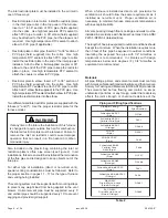
Page 6: ... coupler or 90 elbow to the end of the PVC pipe to keep the restrictor plate in place Use high temperature RTV sealant to attach the coupler or elbow to PVC pipe Restrictor plate in elbow Insert a 3 to 36 section of PVC pipe field supplied into the collar Use high temperature RTV sealant to attach PVC pipe to collar Attach a 90 elbow field supplied to the PVC pipe Use hightemperatureRTVsealanttoat...

Page 7: ... 31 for correct kit is available for use when installing this furnace as a direct vent furnace and the air intake and vent pipe are to be run through the same hole whether horizontally through the wall or vertically through the roof see Figure 3 Refer to the instructions included with the concentric vent kit for installation specifics Vent Pipe Size and Length The vent pipe and air intake pipe in ...

Page 8: ...2 5 2 5 2 5 2 5 2 5 2 5 3 3 3 2 5 2 2 2 5 2 5 2 5 2 5 2 5 2 5 2 5 2 5 2 5 2 5 2 5 2 5 2 5 2 5 2 5 3 3 3 3 3 NR NR NR NR NR NR 0 1 2 3 4 5 6 7 8 9 2 2 2 2 2 2 2 2 2 3 3 3 3 3 3 3 3 3 3 3 3 3 3 3 Vent Pipe Length ft Number of 90 Elbows 5 10 20 30 40 50 60 70 80 90 3 3 3 3 3 3 3 3 3 3 3 3 3 3 3 3 2 5 2 5 2 5 2 5 2 5 2 5 2 5 2 5 2 5 2 5 2 5 2 5 2 5 2 5 2 5 2 5 2 5 2 5 2 5 2 5 2 5 2 5 NR NR NR 2 NR 2 2...

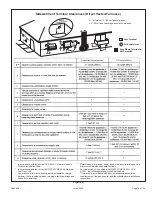
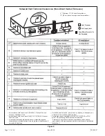
Page 9: ...two single family dwellings and serves both dwellings Permitted only if veranda porch deck or balcony is fully open on a minimum of two sides beneath the floor For clearances not specified in ANSI Z223 1 NFPA 54 or CSA B149 1 the following statement shall be included Clearance in accordance with local installation codes and the requirements of the gas supplier and the manufacturer s installation i...

Page 10: ...en two single family dwellings and serves both dwellings Permitted only if veranda porch deck or balcony is fully open on a minimum of two sides beneath the floor For clearances not specified in ANSI Z223 1 NFPA 54 or CSA B149 1 the following statement shall be included Clearance in accordance with local installation codes and the requirements of the gas supplier and the manufacturer s installatio...

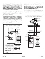
Page 11: ...ed at the termination of the flue pipe and is designed to keep objects out of the flue pipe An additional screen should not be placed in the intake termination If a screen is installed the air intake may freeze shut For horizontal venting refer to Figure 7 For vertical venting refer to Figure 8 It is permissible to run the vent vertically through the roof and terminate it as shown in Figure 8 and ...

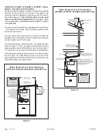
Page 12: ...t the termination of the flue pipe and is designed to keep objects out of the flue pipe For horizontal venting refer to Figure 9 For vertical venting refer to Figure 10 The vent pipe on horizontal runs must slope upward away from the furnace at a minimum pitch of 1 4 per foot of run to prevent accumulation of condensate Prime the trap system by slowly pouring 1 cup of water down the vent pipe On i...

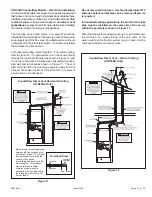
Page 13: ...termination of the flue pipe and is designed to keep objects out of the flue pipe An additional screen should not be placed in the intake termination If a screen is installed the air intake may freeze shut For horizontal venting refer to Figure 11 For vertical venting refer to Figure 12 It is permissible to run the vent vertically through the roof and terminate it as shown in Figure 12 and to run ...

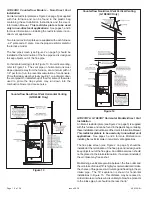
Page 14: ... the combustion blower and cause noise G1D91BT G1D93BT Horizontal Models Direct Vent Installation An inlet air restrictor plate see Figure 2 on page 5 is supplied with this furnace and can be found in the plastic bag containing theseInstallationInstructionsandtheUser sInformationManual This restrictor plate is to be used only in non direct vent applications See pages 5 and 6 for more information o...

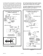
Page 15: ...to the connector on burner box Use high temperature RTV silicone sealant so intake pipe can be removed if service is required In horizontal venting applications the vent and air intake pipe must be installed on the same side of the house within the parameters shown in Figure 15 Figure 16 Horizontal Direct Vent Vertical Venting G1D91BT G1D93BT Only Airflow Left to Right Canadian Installations See C...

Page 16: ...irflow Right to Left Prime the trap system by slowly pouring 1 cup of water down the vent pipe On initial start up of the unit some of the water used to prime the trap system may run down into the combustion blower and cause noise G1D91BT G1D93BT Horizontal Models Non Direct Vent Installation An inlet air restrictor plate see Figure 2 on page 5 is supplied with this furnace and can be found in the...

Page 17: ...orizontal pitch as required in the National Fuel Gas Code ANSI Z223 1 NFPA54 latest edition or the CSA B149 1 Natural Gas and Propane Installation Codes and these instructions Determine that there is no blockage or restriction leakage corrosion or other deficiencies which could cause an unsafe condition 3 As far as practical close all building doors and windows between the space in which the appli...

Page 18: ...n Using 3 4 PVC pipe make a connection from the adapter just installed to extend just outside the unit Install a 3 4 PVC tee as shown in Figure 21 From the tee install the drain to the disposal area The top of the tee must be left open for proper condensate drainage Horizontal Installation Right to Left Airflow Furnace must be mounted such that the side through which the condensate will drain is e...

Page 19: ...oor Install unit at a slight pitch forward see Figure 26 1 Relocate 1 2 NPT plug installed on flue pan to one side of the internal trap assembly as shown in Figure 27 2 Connect the 1 2 NPT plug supplied to the opposite side of the internal trap assembly from the plug installed in Step 1 3 Insert trap assembly supplied into flue pan see Figure 28 4 Connect a length of 3 4 PVC pipe 3 minimum to the ...

Page 20: ... 10 drain pressure switch and the other end shipped loose FOR UPFLOW INSTALLATIONS the loose end is to be connected to the capped tee in the hose assembly leading from the primary pressure switch to the inducer Remove and discard the plastic cap from the tee and connect the hose from the 0 10 drain pressure switch to the tee See Figure 31 Figure 29 Completing Condensate Drain Installation Be sure ...

Page 21: ... loose end MUST be connected to the external drain trap Route hose through gas line access hole in cabinet Then connect to 1 4 barbed fitting on drain trap assembly For right to left airflow installations see Figure 32 For left to right airflow installations see Figure 33 Be sure that the pressure switch hose does not form a trap to hold condensation that could form from the flue gas Hose may be c...

Page 22: ...he furnace A return air duct system is recommended If the unit is installed in a confined space or closet a return connection must be run full size to a location outside the closet The air duct in the closet must be tight to prevent any entrance of air from the closet into the circulating air If there is no complete return air duct system the return air connection must be sealed to the furnace cas...

Page 23: ...ing system at test pressure equal to or less than 1 2 psig 3 5 kPa or 14 W C If the piping system is to be tested at pressures in excess of 1 2 psig 3 5 kPa the furnace and its appliance main gas valve must be disconnected from the gas supply piping system After gas piping is complete carefully check all piping connections factory and field for gas leaks Use a leak detecting solution or other pref...

Page 24: ...led between the return air duct and the side of the furnace Refer to Figure 36 and the following instructions to install the filter rack 1 Using the corner embossments as a guide mark and cut a full size opening in the side panel s Risk of electrical shock Disconnect electrical power at the circuit breaker or service panel before making electrical connections Failure to disconnect power supplies c...

Page 25: ...power is connected to the furnace except when it operates on heating or cooling speed during thermostat call for heat or cooling This constant air terminal is intended for low speed only If a motor is wired for a higher speed the increased amp draw could cause the control board to fail and void the warranty Electronic Air Cleaner Terminals are provided on the integrated ignition blower control boa...

Page 26: ...e floor because some gas is heavier than air and will settle on the floor What to do if you smell gas Do not try to light any appliances Extinguish any open flame Do not touch any electric switch do not use any phone in your building Immediately call your gas supplier from a neighbor s phone Follow the gas supplier s instructions If you cannot reach your gas supplier call the fire department Do no...

Page 27: ... cooling fan speed If the fan is already energized it remains running and does not de energize for the 1 second cooling fan on delay The call for cooling has priority over continuous fan operation while a call for heating has priority over both a call for cooling or continuous fan Ignition lockouts for any reason do not affect cooling operation As cooling demand is met the thermostat de energizes ...

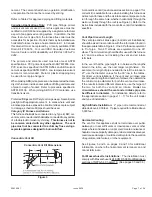
Page 28: ...ing Value The heating value of the gas can be obtained from the local utility company For Propane Gas The only check for the furnace rate is to properly adjust the manifold pressure using a manometer and Table 4 on page 29 Typical manifold set point for installations at altitudes from 0 to 4500 feet above sea level is 10 0 W C Temperature Rise Check the temperature rise and if necessary adjust blo...

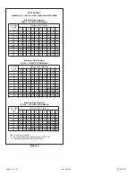
Page 29: ...nstallations above 7500 feet refer to the latest issue of the National Fuel Gas Code and or contact Technical Service at 1 800 448 5872 For installations above 4500 feet fill in the appropiate information on the furnace label that has the words This furnace was converted on For installation above 4 000 ft refer to section Vent Pipe Size and Length on page 7 and Figure 4 on page 8 vent pipe sizing ...

Page 30: ...sewer opening If the condensate drain line becomes blocked or plugged the furnace will not operate properly MAINTENANCE Burners Light the burners and allow to operate for a few minutes to establish normal burning conditions Observe the burner flames Compare this observation to Figure 39 to determine if proper flame adjustment is present Flame should be predominantly blue in color and strong in app...

Page 31: ...Applications only For Canadian Application use IPEX Kit 196005 locally available For a local IPEX Canadian Customer Service Center and kit availability call IPEX at 1 866 473 9462 The following repair parts are available from the local distributor When ordering parts include the complete furnace model number and serial number which are printed on the rating plate located on the furnace Control Gro...

Page 32: ...operation The furnace has a built in self diagnostic capability If a system problem occurs a fault code is shown by an LED on the control board The control continuously monitors its own operation and the operation of the system If a failure occurs the LED will indicate the failure code The flash codes are presented in Table 5 Fault Code History Button The control stores the last five fault codes i...

Page 33: ...C HUM THERMOSTAT SUB BASE HEAT ANTICIPATOR 60 AMP CONDENSER CIRCULATION BLOWER INTERLOCK SWITCH INDUCED DRAFT BLOWER AUX LIMIT LOW VOLTAGE FIELD LOW VOLTAGE FACTORY LINE VOLTAGE FIELD LINE VOLTAGE FACTORY FAULT CODE HISTORY BUTTON SEE NOTE 1 VLT PRESSURE SWITCH IF USED S1 P1 S2 P2 1 HISTORY BUTTON TO DISPLAY FAULT CODES TO ERASE CODES PRESS AND HOLD BUTTON IN FOR MORE THAN 5 SECONDS PRESS AND RELE...

Page 34: ...506305 01 Page 34 of 36 Issue 0938 Figure 41 Schematic Diagram P N 45198 006 ...

Page 35: ...ision can not be met at the time of completion of installaiton the owner shall have a period of thirty 30 days to comply with the above requirements provided however that during said thirty 30 day period a battery operated carbon monoxide detector with an alarm shall be installed 2 APPROVED CARBON MONOXIDE DETECTORS Each carbon monoxide detector as required in accordance with the above provisions ...

Page 36: ...ollowing requirements shall be satisfied by the manufacturer 1 The identification of each special venting system shall include the listing of either the website phone number or manufacturer s address where the venting system installation instructions can be obtained and 2 The special venting systems shall be Product Approved by the Board and the instructions for provided with that system shall inc...

Reviews: