background image

MA 258i

Fieldbus Gateway – EtherNet/IP

en

 04-2017/01

5011

7132

We

 res

er

ve the r

ight to 

ma

ke tec

hnica

l cha

nges

O r i g i n a l   o p e r a t i n g   i n s t r u c t i o n s

Summary of Contents for MA 258i

Page 1: ...MA 258i Fieldbus Gateway EtherNet IP en 04 2017 01 50117132 We reserve the right to make technical changes Original operating instructions...

Page 2: ...Leuze electronic MA 258i 2017 Leuze electronic GmbH Co KG In der Braike 1 D 73277 Owen Germany Phone 49 7021 573 0 Fax 49 7021 573 199 http www leuze com info leuze com...

Page 3: ...uze device 11 3 3 2 Connecting the power supply and the bus cable 11 3 4 Starting the device 11 3 5 MA 258i on EtherNet IP 12 3 5 1 Manually setting the IP address 13 3 5 2 Configure the participant 1...

Page 4: ...lays and operational controls 43 8 1 LED status indicators 43 8 1 1 LED indicators on the circuit board 43 8 1 2 LED indicators on the housing 44 8 2 Internal interfaces and operational controls 45 8...

Page 5: ...well control without EDS support 71 12 3 1 Integrating the hardware into the PLC using the generic EtherNet module 71 12 3 2 Configure the config assembly 73 12 4 Configuration steps for a Rockwell co...

Page 6: ...epairs servicing 96 15 3 Disassembling packing disposing 96 16 Specifications for Leuze end devices 97 16 1 Standard setting KONTURflex S4 switch position 0 97 16 2 Bar code reader BCL 8 S4 switch pos...

Page 7: ...rtant information 1 2 Declaration of Conformity The MA 258i modular interfacing units have been designed and manufactured in accor dance with applicable European directives and standards Notice The De...

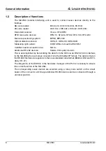
Page 8: ...attro RSX M12 multiNet master connection box MA 3x Additional RS 232 devices Scales third party devices This is accomplished by transmitting the data from the DEV via an RS 232 V 24 interface to the M...

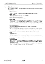
Page 9: ...t is falsified Leuze device DEV Leuze devices e g bar code readers RFID readers VisionReader Online command These commands refer to the respective connected ident device and may be differ ent dependin...

Page 10: ...cases Rooms with explosive atmospheres As stand alone safety component in accordance with the machinery directive 1 For medicinal purposes CAUTION Observe intended use Only operate the device in accor...

Page 11: ...ectricians are able to perform work on elec trical systems and independently detect possible dangers In Germany certified electricians must fulfill the requirements of accident prevention regu lations...

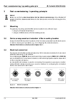
Page 12: ...on can be found in chapter 6 3 1 3 3 Electrical connection The devices from the MA 2xxi family feature four M12 connectors sockets which are coded differently depending on the interface The voltage su...

Page 13: ...and the gateway automatically sets itself to the Leuze device Connecting functional earth FE Ensure that the functional earth FE is connected correctly Unimpaired operation is only guaranteed when th...

Page 14: ...l control using the EDS file if the control supports this PLC software RSLogix 5000 from Rockwell offers EDS support for EtherNet IP from software version 20 00 and up Without PLC support of the EDS i...

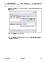
Page 15: ...he DHCP operation via BootP or the Rockwell control must be deactivated Figure 3 2 Manually setting the IP address If your system does not include a DHCP server or if the IP addresses of the devices a...

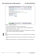
Page 16: ...the service switch to MA Now start a web browser by entering the IP address into the navigation bar You will be shown a page for the direct setting of the addresses Note The service switch must be in...

Page 17: ...4V 3 5 2 Configure the participant Configuration with the generic EtherNet module In the RSLogix 5000 configuration tool for EtherNet IP software version 20 00 a so called generic EtherNet module is c...

Page 18: ...e 107 Optional The address and length of the configuration assembly instance 118 12 x 8bit The possible data lengths are shown in figure 3 5 You can select the suitable byte number for your applicatio...

Page 19: ...ined in the Module properties Connection path in the Request packet interval RPI input field The participant is thereby defined in offline mode the data must subsequently be transferred to the control...

Page 20: ...nted in class 4 under instance 118 By default all param eters are preset to the value 0 zero Attention If the config assembly is not adapted the MA 258i displays a corresponding behavior acc to the pa...

Page 21: ...the device must be created as a module to establish a connection It is also helpful to assign an IP address to the MA beforehand e g via the service interface To do this double click on the tree node...

Page 22: ...ion Notice The available lengths 4 8 12 16 20 32 64 128 240 bytes of the input output data are stored here in fixed combinations They cannot be freely combined The MA can only pro cess ONE combination...

Page 23: ...effectively 10 bytes available for user data on the Leuze device after subtracting the 2 bytes for status and control bytes Recommendation A combination with 4 bytes of output data length is sufficie...

Page 24: ...ng services e g get attributes set attribute and others can be used to acyclically access all data of the MA 258i Attention If parameters are changed via explicit messaging services while simultaneous...

Page 25: ...no special programming by the user is necessary for this purpose The data is not buffered or stored temporarily however Instead it is passed on The programmer must make certain to retrieve the data fr...

Page 26: ...he fieldbus The cable of the respective Leuze device is guided through cable bushings with PG cable glands into the MA 258i and connected there with the PCB connectors The MA 258i is intended as a gat...

Page 27: ...een the Leuze device and the fieldbus is interrupted With this switch position you can communicate directly with the Leuze device at the fieldbus gateway via RS 232 You can send online commands via th...

Page 28: ...with a standard baud rate of 10 100 Mbit The functionality of the device is defined via parameter sets which are clustered in objects classes and instances These objects are contained in an EDS file...

Page 29: ...ure 4 4 EtherNet IP with star topology EtherNet IP linear topology The innovative further development of the MA 258i with integrated switch functionality offers the option of connecting multiple gatew...

Page 30: ...for download from the Leuze home page You can find the EDS file at www leuze com The EDS file is named MA258i eds the corresponding icon is named MA258i ico The EDS file includes all communication par...

Page 31: ...ty none even ODD stop bit 1 Switching input output 1 switching input 1 switching output device dependent voltage Operating voltage 18 30VDC PELV Class 2 1 Power consumption Max 5VA without IDS current...

Page 32: ...Storage temperature range 20 C 60 C Air humidity Max 90 rel humidity non condensing Vibration IEC 60068 2 6 test FC Shock IEC 60068 2 27 test Ea Electromagnetic compatibility EN 61000 6 3 2007 interf...

Page 33: ...cilitating the inte gration of Leuze RS 232 devices in the various fieldbus types Fieldbus Device type Part no PROFIBUS DP V0 MA 204i 50112893 Ethernet TCP IP MA 208i 50112892 PROFINET IO RT MA 248i 5...

Page 34: ...r order and the delivery papers Delivered quantity Device type and model as indicated on the name plate Brief manual The name plate provides information as to what MA 2xxi type your device is For spec...

Page 35: ...24V 6 2 Mounting The gateway mounting plate MA 258i can be mounted in two different ways using four threaded holes M6 or using two M8 screws on the two lateral grooves Fastening by means of four M6 o...

Page 36: ...on which interface is used The housing cover should be easily accessible so that the internal interfaces device interface for connecting the Leuze device via PCB connectors service interface and othe...

Page 37: ...1 Location of the electrical connections 7 1 Safety notices for the electrical connection Attention Before connecting the device please ensure that the supply voltage matches the value print ed on th...

Page 38: ...re 7 2 MA 258i connections Described in detail in the following are the individual connections and pin assignments Attention Voltage supply and bus cable are coded in the same way Please observe the p...

Page 39: ...th connection Switching input output The MA 258i is equipped with the SWIO_1 and SWIO_2 switching inputs outputs This is located on the PWR IN M12 connector and on the PWR OUT M12 connector The connec...

Page 40: ...ction can be separated with a jumper 7 3 BUS IN The MA 258i provides an EtherNet IP interface as a HOST interface Table 7 3 EtherNet IP BUS IN pin assignment PWR OUT 5 pin socket A coded Pin Name Rema...

Page 41: ...t IP interface Ensure adequate shielding The entire connection cable must be shielded and earthed The RD RD and TD TD wires must be stranded in pairs Use CAT 5 cable for the connection MA 258 HOST BUS...

Page 42: ...IN 1 If you use user configurable cables note the following Notice Ensure adequate shielding The entire connection cable must be shielded and earthed The signal lines must be stranded in pairs Use CAT...

Page 43: ...Leuze devices RFI xx RFM xx BCL 22 Figure 7 5 RS 232 device interface The standard devices are connected with 6 or 10 pin connector piece to X31 or X32 respectively For hand held scanners BCL 8 and B...

Page 44: ...n Sub D connector male A crossed RS 232 connection cable is required to make the RxD TxD and GND connections A hardware handshake via RTS CTS is not supported at the service interface Figure 7 7 Conne...

Page 45: ...8 1 LED indicators on the MA 258i 8 1 LED status indicators 8 1 1 LED indicators on the circuit board LED Status off Device OFF no operating voltage or device defect continuous green light Device ok r...

Page 46: ...lly finished device monitoring active flashing green Device ok device in service mode flashing red Configuration error baud rate or address incorrect LED NS flashing green Device ok device in service...

Page 47: ...the following The figure shows the MA 258i with opened housing cover Figure 8 2 Front view operational controls of the MA 258i C B A D E G F Standard settings A MA 258i not equipped B Rotary switch S4...

Page 48: ...uze device JST plug connector with 10 pins Connection of the Leuze devices BCL RFI RFM Pin VINBCL with standard setting V 18 30V X32 Leuze device JST plug connector with 6 pins Connection of the Leuze...

Page 49: ...he configuration of the Leuze device and the MA 258i via PC which is connected by means of a serial null modem cable X33 pin assignment service connector 8 2 4 S10 service switch The S10 DIP switch ca...

Page 50: ...n is only queried after switching off completely and then restarting the device Notice In switch position 0 a distance of 20ms must be maintained between two telegrams so they can be distinguished fro...

Page 51: ...very contents must also be installed For important information on configuring and on the configurable functions please refer to the description of the respective device 9 1 Connecting the service inte...

Page 52: ...e connected Leuze device Commands You can now call up information on the MA 258i by sending the following commands Table 9 1 Available commands Information Table 9 2 General firmware information v Gen...

Page 53: ...emory could not send Number of good ASCII send frames Number of frames that the ASCII memory sent successfully ND Current status of ND bit W Ack Current status of W Ack bit R Ack Current status R Ack...

Page 54: ...iguration 52 MA 258i Leuze electronic Table 9 6 Communication parameters MA 258i Gateway address Displays the set gateway address Network mask Displays the set network mask DHCP DHCP mode ENABLED DISA...

Page 55: ...ture is used between fieldbus gateway PLC Only the data part with the corresponding frame e g STX CR LF is then transmitted between the fieldbus gateway and the Leuze end device The two control bytes...

Page 56: ...0 7 6 5 4 3 2 1 0 ND BO DL BLR DEX SMA W ACK Status byte 0 DLC7 DLC6 DLC5 DLC4 DLC3 DLC2 DLC1 DLC0 Status byte 1 Data byte parameter byte 0 Data Data byte parameter byte 1 Bit no Designation Meaning 0...

Page 57: ...th for the transmission of data to the transmit buffer with the CTB command and for sending the transmit buffer contents with the SFB command 0 0 Bit 0 1 Successfully written 1 0 Successfully written...

Page 58: ...ddr Data type Value range Default DL Data loss Data transmission monitoring This bit is set until the device is reset bit pattern see chapter 10 4 RESET function deleting memory in case gateway data w...

Page 59: ...e PLC This can be used to differentiate between multiple identical data sets that are sent to the PLC 0 7 Bit 0 1 1 0 On each status changefornewdata 0 Input data Description Addr Data type Value rang...

Page 60: ...ted Leuze device can be set in the data or parameter field For further information see chapter 11 1 3 Command mode 0 0 Bit 0 Default transparent data transmission 1 Command mode 0 Output data Descript...

Page 61: ...to receive the next data set This toggle bit is switched by the master after valid received data has been read out of the input bytes and the next datablock can be requested If the gateway detects a...

Page 62: ...for this purpose if 20 ms is pending Control byte 0 10101010 AAh Control byte 1 10101010 AAh OUT data byte 0 parameter byte 0 AAh OUT data byte 1 parameter byte 1 AAh This sets the memory or status co...

Page 63: ...mode In Collective mode the data of the serial end device is stored temporarily in the fieldbus gateway by toggling the CTB bit and is not sent to the PLC in blocks until prompted to do so by the PLC...

Page 64: ...y the master to the slave is first collected in a transmit buffer by setting the CTB bit Copy to transmit buffer Please observe that data provided is transmitted directly by toggling the bit The data...

Page 65: ...to a is to be entered in control or output byte 2 To deactivate the reading gate a 2D hex must be used instead corresponds to a ASCII 7 6 5 4 3 2 1 0 ND Address 4 Address 3 Address 2 Address 1 Addres...

Page 66: ...ffer DEX 1 set status bit 0 3 Transmit the next data with toggle bit R ACK R ACK control bit 1 0 Confirmdataretrievalwith toggle bit R ACK R ACK control bit 1 0 No No Yes Yes Sending of data Number 25...

Page 67: ...ce is to be queried the corresponding bit is to be set so that a v is sent to the Leuze device with the STX v CR LF frame The Leuze end device also answers the gateway with data e g bar code content N...

Page 68: ...d the ND bit and the selected bit in byte 2 must be toggled byte 0 0 can stay No No Yes Yes Bit 0 0 1 Byte 2 Bit set Connected device can only be addressed via HW or PLC data telegram e g Bit 0 0 sign...

Page 69: ...le commands can be found in chapter Specifications for Leuze end devices on page 97 Triggering scanner Reception of data Has the slave re ceived data from the RS 232 BLR BLR Rescue data e g data block...

Page 70: ...ensure protection class IP 65 Finally close the housing of the MA 258i Attention Only then may the supply voltage be applied Upon startup of the MA 258i the device selection switch is queried and the...

Page 71: ...ology in which the MA 258i is operated see EtherNet topologies on page 34 On delivery the automatic address assignment via DHCP server is defined as the standard setting of the MA 258i 12 2 1 Manually...

Page 72: ...vice switch to MA Now start a web browser by entering the IP address into the navigation bar You will be shown a page for the direct setting of the addresses Notice The service switch must be in switc...

Page 73: ...well control without EDS support 12 3 1 Integrating the hardware into the PLC using the generic EtherNet module In the RSLogix 5000 configuration tool for EtherNet IP software version 20 00 a so calle...

Page 74: ...06 Optional The address and length of the configuration assembly instance 118 12 x 8bit The possible data lengths are shown in figure 12 5 You can select the suitable byte number for your application...

Page 75: ...nsferred to the control 12 3 2 Configure the config assembly The MA 258i makes available a configuration assembly that allows the entire parameter set of the MA 258i to be saved in the control and if...

Page 76: ...ice was integrated into an older version control without EDS support using the generic module the following option exists to change parameters of the MA After setting up the device with the generic mo...

Page 77: ...n Leuze electronic MA 258i 75 TNT 35 7 24V Figure 12 6 Entering the byte parameters Transfer the settings made to the device via EtherNet module Properties via Reset module Figure 12 7 Transferring ma...

Page 78: ...he EDS file for the device via EDS wizard into the PLC database Notice You can find the EDS file at www leuze com After loading select the device via the device list and enter it into the HW manager v...

Page 79: ...figuration Leuze electronic MA 258i 77 TNT 35 7 24V Figure 12 8 Creating a module First set the IP address Figure 12 9 Setting the IP address of the MA Attention The IN OUT combinations can only be se...

Page 80: ...ths of the input and output data Notice Since the combination of Produced Consumed data contains 2 bytes for the control and status bytes the actual user data length is always 2 bytes smaller than spe...

Page 81: ...anners BCL The larger data lengths are on the other hand relevant for 2D code scanners hand held scanners LSIS and RFID Notice The representation of the Rockwell control is usually set to double word...

Page 82: ...ster The identity object contains among other things a manufacturer specific vendor ID as well as an ID that describes the principle function of the participant The MA 258i has the following identity...

Page 83: ...ed by Leuze electronic as a communications adapter According to ODVA the MA 258i is assigned number 12D 0CH 12 6 1 3 Product Code The product code is an ID assigned by Leuze electronic that has no fur...

Page 84: ...When doing so the values of the input and output data lengths must be manually entered according to the following table Bit 7 Bit 6 Bit 5 Bit 4 Bit 3 Bit 2 Bit 1 Bit 0 ext device state reserved confi...

Page 85: ...ntent with max 14 bytes 16 16 Data 20 In 20 Out Data content with max 18 bytes 20 20 Data 32 In 32 Out Data content with max 30 bytes 32 32 Data 64 In 64 Out Data content with max 62 bytes 64 64 Data...

Page 86: ...ine mode Byte 04 05 Baud rate Byte 06 07 Data bits Byte 08 09 Parity Byte 10 11 Stop bits Data Mode Parameter value 0d 0000h Transparent mode default 1d 0100h Collective mode Byte 0 1 0000h LowByte fi...

Page 87: ...000h 19200 384d 8010h 38400 576 d 4020h 57600 1152d 8040h 115200 Byte 4 5 6000h LowByte first RS 232 Data Bits Parameter value 7d 0700h 7 bits 8d 0800h 8 bits default Byte 6 7 0800h LowByte first RS 2...

Page 88: ...nnector via the RS 232 cable On the PC call up a terminal program e g BCL Config and check whether the interface COM 1 or COM 2 to which you have connected the MA 258i is set to the following Leuze st...

Page 89: ...tor voltage on PIN 9 The corresponding cable is to be selected for the respective hand held scanner and ordered separately The 9 pin Sub D cable KB JST HS 300 part no 50113397 is connected to this cab...

Page 90: ...bination with an RFID device Notice Also note that all characters which are sent to a transponder are hex encoded ASCII char acters Each of these hexadecimal characters is in turn to be handled as an...

Page 91: ...data toggle CTB PWR status LED on the circuit board Off No supply voltage connected to the device Check supply voltage Hardware error Send the device to customer service Green orange flashing Device...

Page 92: ...Incorrect wiring Check wiring Different protocol settings Check protocol settings Protocol not released Activate TCP IP or UDP Sporadic errors at the EtherNet IP interface Incorrect wiring Check wirin...

Page 93: ...tion MA 204i PROFIBUS gateway 50112893 MA 208i Ethernet TCP IP gateway 50112892 MA 235i CANopen gateway 50114154 MA 238i EtherCAT gateway 50114155 MA 248i PROFINET IO RT gateway 50112891 MA 255i Devic...

Page 94: ...30 C 70 C in motion 5 C 70 C Material sheathing PVC Bending radius 50mm PWR IN 5 pin socket A coded Pin Name Core color 1 VIN brown 2 SWIO_2 white 3 GND blue 4 SWIO_1 black 5 FE gray Thread FE bare P...

Page 95: ...igure 14 1 Cable structure of Industrial EtherNet connection cable Type designation Description Part no K D M12A 5P 5m PVC M12 socket for PWR axial plug outlet open cable end cable length 5m 50104557...

Page 96: ...Part no M12 connector for BUS IN axial connector open cable end KB ET 1000 SA Cable length 1m 50106738 KB ET 2000 SA Cable length 2m 50106739 KB ET 5000 SA Cable length 5m 50106740 KB ET 10000 SA Cab...

Page 97: ...able length 3m 50113468 KB JST M12A 8P 3000 LSIS 122 LSIS 222 cable length 3m 50111225 K D M12A 5P 5m PVC Voltage supply cable length 5m 50104557 K D M12A 5P 10m PVC Voltage supply cable length 10m 50...

Page 98: ...or service organization should repairs be required The addresses can be found on the inside of the cover and on the back Notice When sending devices to Leuze electronic for repair please provide an ac...

Page 99: ...g KONTURflex S4 switch position 0 This switch position can be used with almost all devices since a data frame is transmitted along with it if necessary A 00h in the data range of the control is interp...

Page 100: ...umed data settings Dependent on number of beams used but at least 20 bytes In 4 bytes Out User parameters Transparent mode Use ESD settings baud rate 38400 4 data bits No parity 2 stop bits KONTURflex...

Page 101: ...20 bytes In 4 bytes Out combination Default parameter BCL 8 Baud rate 9600 Data mode 8N1 Handshake no Protocol framing protocol without acknowledgment Frame STX Data CR LF Control bit Meaning Corresp...

Page 102: ...In 4 bytes Out combination Default parameter BCL 22 Baud rate 9600 Data mode 8N1 Handshake no Protocol framing protocol without acknowledgment Frame STX Data CR LF Control bit Meaning Corresponds to s...

Page 103: ...xample it is advisable to use the 20 bytes In 4 bytes Out combination Default parameter BCL 300i BCL 500i BCL 600i Baud rate 9600 Data mode 8N1 Handshake no Protocol framing protocol without acknowled...

Page 104: ...nt on the number of digits of the bar code that is to be read With an 18 digit bar code 2 bytes of status bytes for example it is advisable to use the 20 bytes In 4 bytes Out combination Default param...

Page 105: ...umber of digits of the 2D code that is to be read With an 18 digit bar code 2 bytes of status bytes for example it is advisable to use the 20 bytes In 4 bytes Out combination Default parameter LSIS 12...

Page 106: ...mended settings Produced Consumed data settings dependent on the number of digits of the 2D code that is to be read With an 18 digit bar code 2 bytes of status bytes for example it is advisable to use...

Page 107: ...d held scanners Recommended settings Produced Consumed data settings dependent on the number of digits of the bar code that is to be read With an 12 digit bar code 2 bytes of status bytes for example...

Page 108: ...code that is to be read For the reading of a 16 digit serial number 2 bytes of status bytes for example it is advisable to use the 64 bytes In 8 bytes Out combination The RFID devices expect the tele...

Page 109: ...t In this switch position the MA automatically sends a position request to the BPS 8 every 10ms until another command comes via the control Automatic request only restarts when a new position request...

Page 110: ...11 2 Recommended settings Produced Consumed data settings 20 bytes In 8 bytes Out Default parameter BPS 300i Baud rate 38400 Data mode 8N1 Handshake no Protocol binary protocol without acknowledgment...

Page 111: ...ponding device Specifications for the serial interface Specifications for Command mode Command mode cannot be used with the ODSL 9 ODSL 30 and ODSL 96B The ODSL 9 96B is to be operated in the Precisio...

Page 112: ...its of the code that is to be read With an 18 digit bar code 2 bytes of status bytes 2 bytes of slave address for example it is advisable to use the 64 bytes In 4 bytes Out combination Notice In this...

Page 113: ...of the MA that can be configured with software such as baud rate IP address dependent on type to the factory settings do the following Set device switch S4 to F in a voltage free state Switch the volt...

Page 114: ...C1 DEVICE CONTROL 1 X ON Device control character 1 12 18 R DC2 DEVICE CONTROL 2 TAPE Device control character 2 13 19 S DC3 DEVICE CONTROL 3 X OFF Device control character 3 14 20 T DC4 DEVICE CONTRO...

Page 115: ...51 3 34 52 4 35 53 5 36 54 6 37 55 7 38 56 8 39 57 9 3A 58 COLON Colon 3B 59 SEMICOLON Semicolon 3C 60 LESS THAN Less than 3D 61 EQUALS Equals 3E 62 GREATER THAN Greater than 3F 63 QUESTION MARK Ques...

Page 116: ...T Grave accent 61 97 a 62 98 b 63 99 c 64 100 d 65 101 e 66 102 f 67 103 g 68 104 h 69 105 i 6A 106 j 6B 107 k 6C 108 l 6D 109 m 6E 110 n 6F 111 o 70 112 p 71 113 q 72 114 r 73 115 s 74 116 t 75 117 u...

Page 117: ...device 11 Power supply and bus cable 11 Safety notices 35 Ethernet connection cable 93 F Fast commissioning 10 Fieldbus systems 26 G Generic module 16 72 I Input byte 0 Buffer overflow 56 Data exist...

Page 118: ...fer 60 Read Acknowledge 59 Send data from buffer 59 P Packing 96 Q Quality assurance 5 R Reading slave data 62 Repair 96 S Service interface 42 47 Service mode Commands 50 Information 50 Service switc...

Reviews: