Phenolic Base Lampholder
Rated: 75W-125V
Cat. No. 2152
Incandescent Only
INSTALLATION INSTRUCTIONS
Douille à culot en résine phénolique
Valeurs nominales : 75 W, 125 V
Nº de cat. 2152
Pour lampes à incandescence seulement
DIRECTIVES D’INSTALLATION
Portalámpara con Base de Fenólico
Capacidad: 75W-125V
No. de Cat. 2152
Sólo Incandescente
INSTRUCCIONES DE INSTALACION
ENGLISH
The Cat. No. 2152 is a phenolic base lampholder assembly. It is mounted with the enclosed mounting bracket
and uses a 4-Watt bulb. To order replacement bulbs, order Cat. No. 12414.
WARNING:
TO BE INSTALLED AND/OR USED IN ACCORDANCE WITH APPROPRIATE ELECTRICAL
CODES AND REGULATIONS.
WARNING:
IF YOU ARE NOT SURE ABOUT ANY PART OF THESE INSTRUCTIONS, CONSULT A
QUALIFIED ELECTRICIAN.
CAUTION:
AVOID CONTACT OF BULB WITH FLAMMABLE MATERIALS. DO NOT COVER LIGHT WITH
DRAPES, BLANKETS ETC. OR BLOCK VENTILATION, AS OVERHEATING MAY OCCUR. TO AVOID FIRE
HAZARD, USE ONLY A 4-WATT BULB!
CAUTION:
USE THIS DEVICE ONLY WITH COPPER OR COPPER CLAD WIRE. WITH ALUMINUM WIRE
USE ONLY DEVICES MARKED CO/ALR OR CU/AL.
TO INSTALL:
1.
WARNING:
TO AVOID FIRE, SHOCK, OR DEATH; TURN OFF POWER AT CIRCUIT BREAKER OR
FUSE AND TEST THAT POWER IS OFF BEFORE WIRING!
2.
In a retrofit application, remove the old device from the electrical box.
3.
Screw light bulb provided into lampholder.
4.
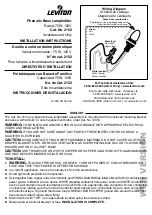
Twist together bare copper ends of conductors per WIRING DIAGRAM as follows: BLACK (Hot) conductor from
power source to BLACK wire on device. WHITE (Neutral) conductor from power source to WHITE conductor on
device. Twist strands of each lead tightly and push firmly into appropriate wire connector. Screw connectors
on clockwise making sure that no bare conductor shows below wire connectors. Secure each connector
with electrical tape. To ground the device, loop GREEN or BARE COPPER ground wire around the GREEN
hex screw provided. Tighten screw firmly.
5.
Mount device with “TOP” up in appropriate location using the screws provided.
6.
Restore power at circuit breaker or fuse.
INSTALLATION IS COMPLETE.
DI-000-02152-20A
For Technical Assistance Call:
1-800-824-3005 (U.S.A. Only) / www.leviton.com
Pour toute aide technique, composer le :
1-800-405-5320 / www.leviton.com
Para Asistencia Técnica llame al:
1-800-824-3005 (Sólo en E.U.A.) / www.leviton.com
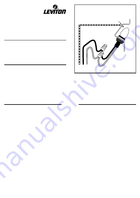
Wiring Diagram
Schéma de cablage
Diagrama de Cableado
Black (hot)
Noir (actif)
Negro (fase)
White (neutral)
White (neutre)
Blanco (neutro)
Green
Vert
Verde
Green hex screw location
Emplacement de la vis hexagonale verte
Ubicación del tornillo verde exag.
WEB
VERSION


