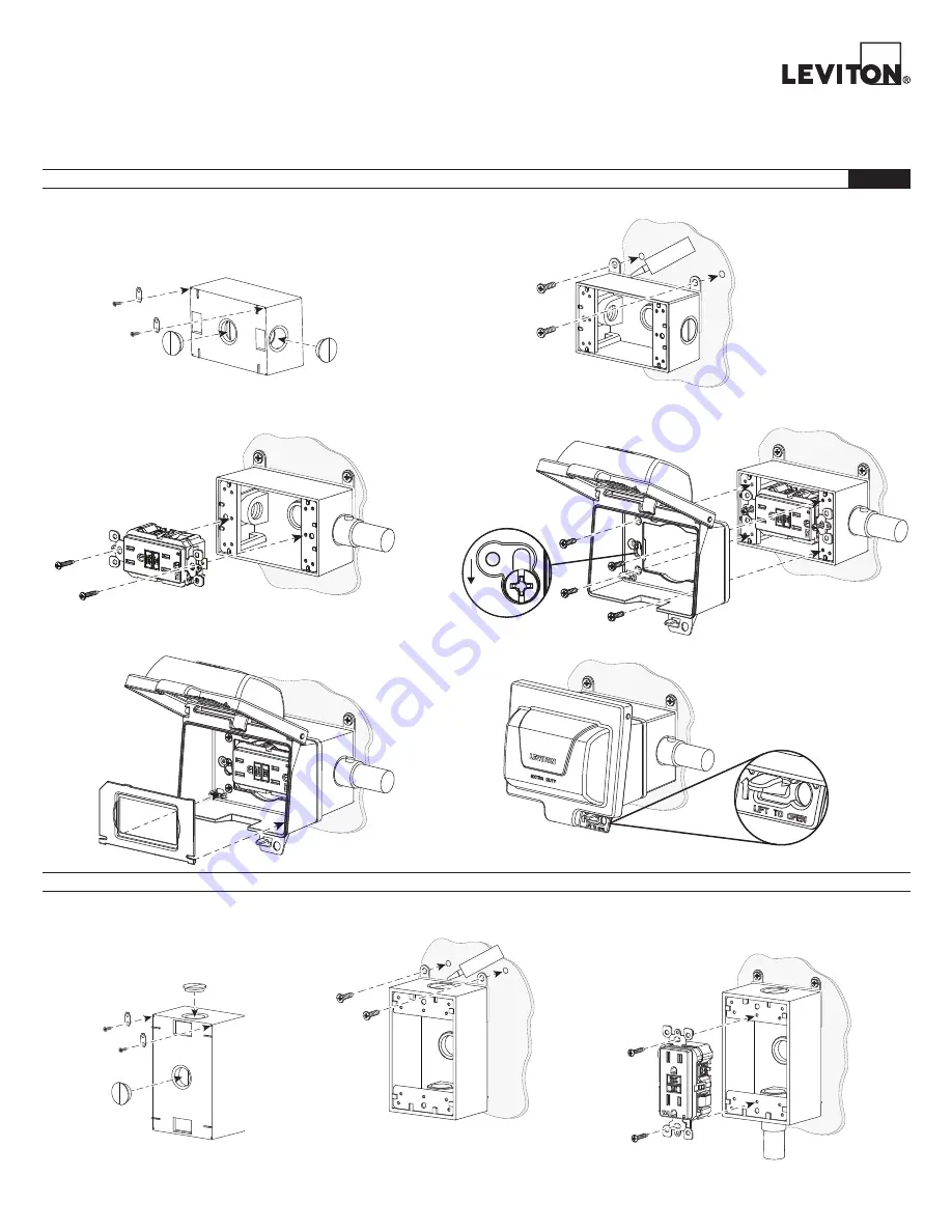
While-In-Use Metal Cover
One Gang - Horizontal and Vertical Mount - Extra Duty
Cat. Nos. IUM1H, IUM1V
PK-A3303-10-02-2A
1.
Insert plugs and attach mounting tabs.
Cat. No. IUM1H-KBG is shown.
NOTE:
No back box is inlcuded with Cat. No. IUM1H-KRG
proceed to step 3.
2.
Mount box.
2.
Mount box.
3.
Install GFCI.
NOTE:
Follow GFCI instruction sheet for wiring instructions.
6.
Lift to Open.
4.
a. Mount cover onto 2 mounting screws and tighten in place.
b. Attach cover onto backbox with screws (4).
a.
b.
5.
Install insert.
Leave GFCI mounting screws 3/8" out for cover installation.
Leave GFCI mounting screws 3/8" out for cover installation.
WARNINGS:
•
TO AVOID FIRE SHOCK OR DEATH TURN OFF POWER AT CIRCUIT BREAKER OR FUSE AND TEST THAT POWER IS OFF BEFORE WIRING
.
• TO BE INSTALLED AND/OR USED IN ACCORDANCE WITH APPROPRIATE ELECTRICAL CODES AND REGULATIONS.
Silicone
HORIZONTAL MOUNT INSTALLATION
ENGLISH
VERTICAL MOUNT INSTALLATION
1.
Insert plugs and attach mounting tabs.
Cat. No. IUM1H-KBV is shown.
NOTE:
No back box is inlcuded with
Cat. No. IUM1H-KRV proceed to step 3.
Silicone
3.
Install GFCI.
NOTE:
Follow GFCI instruction sheet for wiring instructions.
WEB
VERSION


