PHOTOCELLS
CAT. NOS. PCIND, PCOUT, PCATR, PCSKY
INSTALLATION INSTRUCTIONS
WARNINGS AND CAUTIONS:
•
TO AVOID FIRE, SHOCK, OR DEATH; TURN OFF POWER AT CIRCUIT BREAKER OR FUSE AND TEST THAT
POWER IS OFF BEFORE WIRING!
• To be installed and/or used in accordance with appropriate electrical codes and regulations.
• If you are unsure about any part of these instructions, consult an electrician.
• SAVE THESE INSTRUCTIONS.
WARNINGS AND CAUTIONS:
• Read and understand all instructions. Follow all warnings and instructions marked on the product.
• Installer must be a qualified and experienced service technician.
• Verify the product ratings to confirm that this product will satisfy your requirements and application prior to installation.
PK-A3023-10-00-0A
OVERVIEW
Leviton Photocells monitor ambient light levels and provide a DC analog
signal to various microprocessors and energy management systems for
the purpose of lighting control. There are 4 different styles with 4 different
possible ranges for a total of 16 basic varieties.
Styles Include: Indoor, Outdoor, Atrium and Skylight
Ranges Include: 0-5V, 1-5V, 0-10V & 1-10V
All 16 varieties require a Class 2 Low Voltage Power Supply providing
12-24VDC input power to operate properly.
The four different styles of Leviton Photocells have different mounting and
installation requirements which are covered in the installation section.
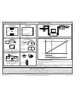
INSTALLATION
Indoor Photocell – PCIND (Ceiling)
Mount the Indoor photocell in a 1/2” hole in the false ceiling tile using the
adhesive backing. For most general applications the photocell should be
mounted between 6-8 feet of the window area, central to the area illuminated
by the electrical lighting that will be controlled. In all cases the photocell must
be mounted so that it looks at reflected light only and not at any direct light.
(See Figure 1A)
Indoor Photocell - PCIND (Reflecting Wall)
Mount the Indoor photocell at a reflecting wall. When sconces are in place in
the light well, make sure not to mount photocell in direct level as the sconces.
Place photocell 18” from the bottom corner of the ceiling. Remember, the
Fresnel lens will see light with a field of view that is 1.15 times the distance to
the wall. No direct lighting should be within the field of view.
(See Figure 1C)
Outdoor Photocell - PCOUT
Mount the Outdoor photocell in a standard threaded 1/2” conduit or 1/2”
knockout. Locate the photocell on the roof or somewhere that is exposed
to full daylight and is not shadowed or directly exposed to any night-time
illumination. Photocell must be mounted horizontally, facing North, with the
hooded portion on top.
(See Figure 1E)
Atrium Photocell - PCATR
Mount the Atrium Photocell in a standard threaded 1/2” conduit or 1/2”
knockout. Locate the photocell at the opposite side of the window mounting
the photocell against the wall or ideally in the middle of the atrium expance,
facing towards the Atrium glass.
(See Figure 1B)
Skylight Photocell - PCSKY
Mount the Skylight photocell in a standard threaded 1/2” conduit or 1/2”
knockout. Locate the assembly near the center of the skylight well (at least
12” from the side) that is exposed to full daylight and is not shadowed. For the
best results, use uni-strut with a 1/4” angle support, making sure the top of
the light photocell is level with top of skylight curb. Photocell must be mounted
vertically with the domed portion facing up.
(See Figure 1D)
Leviton Photocells are a three-wire device that can provide DC analog
voltage inputs to a variety of controllers and microprocessors. In most cases,
a 12-24 VDC power source must be supplied to the RED and BLACK wires
on the photocell. The photocell will draw 24mW of power. The DC signal
voltage is returned to the controller through the YELLOW wire. Wiring the
photocell to the controller should be done with 18-22 AWG stranded wire.
(See Figure 2)
• Do not route the low voltage wire with or near AC power wiring.
• For long wire runs or where there is excessive electrical noise, shielded
cable or cable in conduit is required.
• Cable lengths should not exceed 500 ft.
• Butt splices are recommended but wire nuts are acceptable.
• Wiring should be performed with all relevant power switched off.
RED:
Input Voltage (+12-24VDC)
BLACK: Input Return/Output common (+12-24VDC)
YELLOW: Output Signal to Controller (0-5, 1-5, 0-10, 1-10VDC)
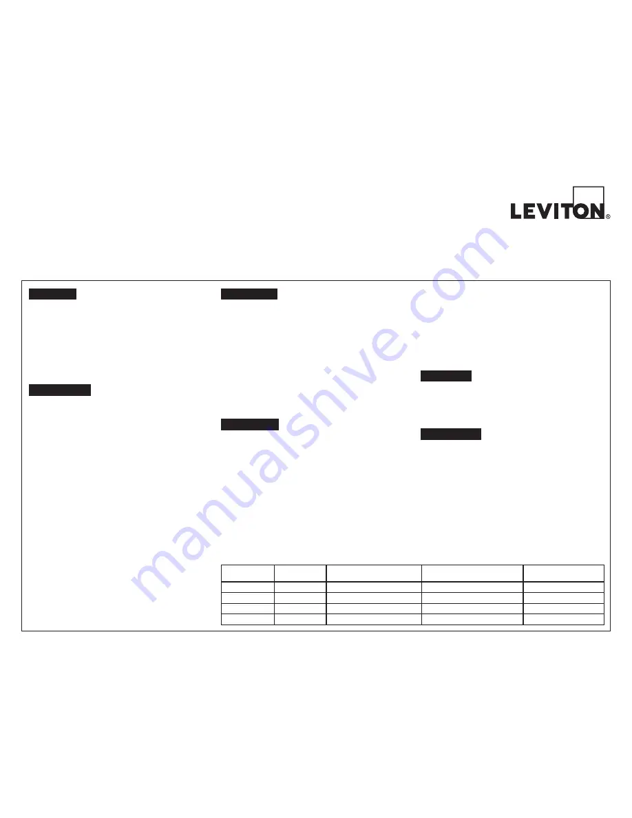
CONNECTION
PHOTOCELL
STYLE
FIXED CORRESPONDING
FOOT-CANDLE MIN.
ADJUSTABLE CORRESPONDING
FOOT-CANDLE RANGES
FACTORY SET MAX.
PCIND
Indoor
0 Foot-candles
50-750 Foot-candles
100 Foot-candles
PCOUT
Outdoor
0 Foot-candles
50-750 Foot-candles
250 Foot-candles
PCATR
Atrium
0 Foot-candles
200-2,000 Foot-candles
1,000 Foot-candles
PCSKY
Skylight
0 Foot-candles
1,000-7,500 Foot-candles
2,000 Foot-candles
CALIBRATION
Leviton Photocells have a variable gain that can be adjusted by turning the trim
pot screw that is accessible through the small hole in the side of the photocell
housing.
However, making field adjustments are strongly discouraged as
most field technicians do not have the equipment to do the job with any
degree of precision. Leviton Photocells are factory calibrated to values that
are time tested for their applications. If the factory calibration has been altered,
a recalibration fee will be charged to return the photocell to factory settings. If a
field adjustment must be made, the following information should prove useful.
The Maximum range of a Leviton photocell should be at least 50% higher than
the highest set point of interest in the lighting control zone that is controlled by
the photocell.
• To increase the output signal voltage at a given light level, rotate the trim
pot screw clockwise.
• To decrease the output signal voltage at a given light level, rotate the trim
pot screw counter-clockwise.
The signal response of Leviton photocells is very linear. If an accurate reading of
the foot-candle level that the photocell is exposed to is available, the maximum
range can be set using some basic math.
Example: If the photocell is exposed to 150FC, and 300FC Maximum is
desired, adjust the trim pot until the signal voltage is 5VDC for a 0-10V
photocell.
When calibration is complete, be sure to replace the plastic screw and washer
to seal the hole from dust and water. If there does not seem to be enough
information here to adjust the photocell’s gain, you should rely on the factory
setting or call technical support for additional help.
NOTE: Field adjustment of the photocell’s gain is not recommended.
Leviton Photocells are functioning when the EMS system analog status
changes as the photocell detects light. Once calibrated, the photocell
will need no further attention. Except for the calibration hole there are no
switches or other user controls on the photocell.
OPERATION
Every 2 months wipe the lens clean with a non-scratching clean cloth and
ensure that no foreign debris remains. Check the housing for damage
such as cracks, burns or other deformations. Check that no moisture has
penetrated the photocell, as this will likely render it inoperable.
MAINTENANCE


