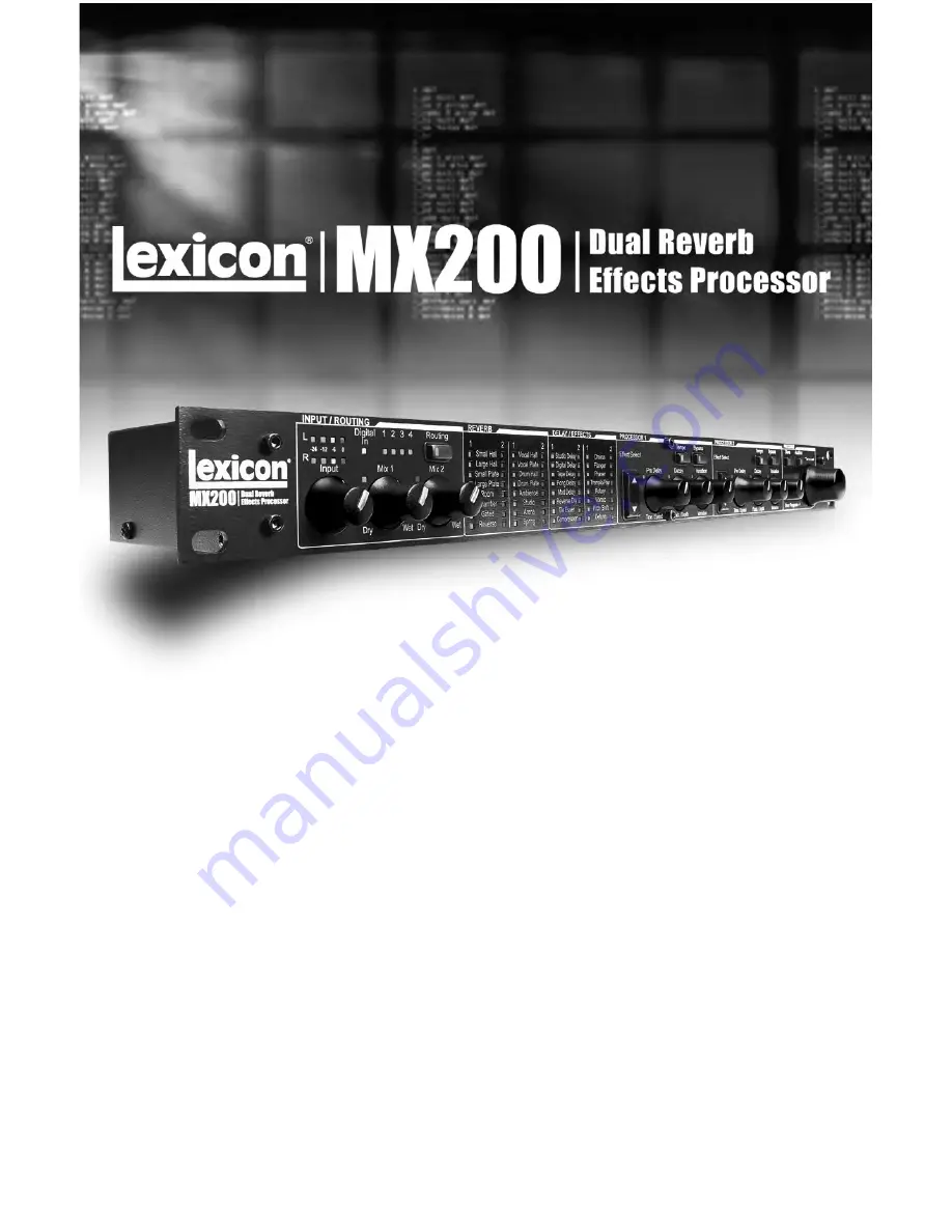
background image

MX200

User 

Guide


Summary of Contents for MX200

Page 1: ...MX200 User Guide ...

Page 2: ......

Page 3: ...re all parts and labor will be covered up to a period of 1 year A Return Authorization number must be obtained from Lexicon Professional by telephone The company shall not be liable for any consequential damage asa result of the product s use in any circuit or assembly 4 Lexicon Professional reserves the right to make changes in design or make additions to or improvements upon this product without...

Page 4: ......

Page 5: ...nd Mono Output Modes 24 Factory Program Banks Serial and Parallel 24 Bypass Mode Select 25 Factory Reset 25 The MX Edit Editor Librarian Windows 26 Minimum System Requirements 26 Installing the MX Edit Editor Librarian Software 26 Quick Start 26 The MX Edit Library 27 Opening or Creating a Program 27 The MX Edit Program Editor 28 Editing a Program 28 Saving a Program 30 Storing a Program 30 Archiv...

Page 6: ...ardware Plug In 35 Connecting the MX200 35 Software Configuration 36 Using the MX200 Plug In Window 36 Controls 36 MIDI Port Error Message 37 CC Mapping 37 MIDI Implementation Chart 37 Specifications 38 Appendix 39 Program List 40 ...

Page 7: ...ition 4 Set the Mix 1 and Mix 2 knobs on the MX200 to their full clockwise position Wet 5 Provide source signal by speaking or singing into the mic playing guitar keyboard etc on the selected mixer channel 6 Turn up the Aux Send level on the channel corresponding to the Post fader send Aux 1 in this example that the MX200 is connected to until the Red Input LEDs light only occasionally If the red ...

Page 8: ...les through the effect processors There are five audio samples included in the MX200 including various drum sounds vocal and guitar In the factory setting tap ping the Audition button cycles through the five sounds but you may want to repeat a particular sound as you choose or edit an effect See page 11 for more infor mation Audition Button 2 ...

Page 9: ...functioning within a VSTTM or Audio Units compatible recording appli cation as a plug in effect but still operating as a dedicated hardware processor This unique hardware plug in feature lets you add legendary Lexicon effects to your com puter based recordings with full automation and recall features via an intuitive cross platform plug in window without overbur dening your CPU Live Operation Thos...

Page 10: ...hich allows no signal wet or dry to pass see Bypass Mode Select in the Utilities section on page 25 7 Tempo Button P2 Same as for Processor 1 see 5 8 Bypass Button P2 Bypasses Processor 2 Red LED lights to indicate effect is bypassed 9 Store Button Stores program modifications to one of the 99 User program locations Press the Store and Audition buttons simultaneous ly to access Utility functions S...

Page 11: ...he selected effect in Processor 1 18 Effect Select P2 Same as for Processor 1 see 14 19 Pre Delay Knob P2 Same as for Processor 1 see 15 20 Decay Knob P2 Same as for Processor 1 see 16 21 Variation P2 Same as for Processor 1 see 17 22 Program Display 2 character LED display indicates which of the 99 Factory or User programs is loaded A small dot appears at the bottom right of the Program Display w...

Page 12: ...l device to the MX200 s S PDIF input that transmits at any other sample rate such as 96kHz Doing so can cause unpredictable performance Make sure the device you are connecting to the MX200 s S PDIF In is set as the Clock Master if that option is available and transmitting at a sample rate of 44 1kHz or 48kHz only As with any other connection if you need to unplug the S PDIF cable it is recommended...

Page 13: ...ffects such as tremolo vibrato and rotary The following illustrations show how to connect the MX200 in both Serial and Parallel configurations using some com mon real world examples Parallel Connection Mixer Mono In Stereo Out Setup This setup is the most commonly used configuration in both live and studio appli cations 1 Select routing 2 or 4 using the Routing button 2 Connect the mixer s Post Fa...

Page 14: ...stereo 5 Set Mix 1 and Mix 2 knobs fully clockwise Wet 6 Set the MX200 s Input knob to the 12 o clock position 7 Set the Aux Return levels on the mixer to 12 o clock 8 Turn up Aux Sends 1 and 2 on the mixer for the selected channels so the red Input Bargraph LEDs only light occasionally with signal adjusting the Input knob on the MX200 may be necessary 9 Control the amount of effect using the Aux ...

Page 15: ... Studio Digital Setup This setup is ideal if you are using the MX200 as a hardware plug in in a digital recording system This setup requires that you are using an I O device with S PDIF In Out or a digital mixer with S PDIF I O option 1 Select routing 2 using the Routing button You can always experiment with other routings 2 Connect the S PDIF output on your soundcard audio interface or mixer to t...

Page 16: ...ram Display while the knob is being turned A small LED next to the knob will illuminate denoting a change from the saved value and the Store button will light indicating that the loaded program has been modified To retain these changes you must store them to a User program location see Storing Programs Knob and button LEDs are green for Processor 1 and red for Processor 2 to correspond with their ...

Page 17: ...t The Audition Feature The Audition feature provides 5 digitally recorded audio samples that are played back through MX200 s processors at the touch of a button This lets you preview the selected program and dial in reverb or effects settings without the need for an external audio source In the default setting each tap of the Audition button plays the next sample To play a single sample repeatedly...

Page 18: ...ssors are then mixed together and routed to both the outputs as a single stereo signal 4 Mono Split Left input signal is sent through Processor 1 while the Right input signal is sent through Processor 2 The output signals of both processors are then mixed together and routed to both the outputs as a single stereo signal Storing Programs Once you have edited a program to your liking you can store t...

Page 19: ...all is designed to emulate the acoustics of a concert hall a space large enough to contain an orchestra and an audience Because of the size and characteristics Halls are the most natural sounding reverbs designed to remain behind the direct sound adding ambience and space but leaving the source unchanged This effect has a relatively low initial echo density which builds up gradually over time Voca...

Page 20: ...ams useful on a wide range of material especially the spoken voice to which Chamber programs add a noticeable increase in loudness with low color Gated reverb is created by feeding a reverb such as a metal plate through a gate device Decay Time is set to instant while Hold Time varies duration and sound The Gated reverb provides a fairly con stant sound with no decay until the reverb is cut off ab...

Page 21: ...Delay time may help clarify it and set each instrument apart from each other Decay Controls the amount of time the reverb can be heard Higher settings increase rever beration times which are usually associat ed with larger acoustical environments but can decrease intelligibility Lower settings shorten reverb times and should be used when a smaller apparent space or a more subtle effect is desired ...

Page 22: ...is displayed as 00 in the Program Display Values of greater than 100 are shown with a decimal between the digits i e 115 displayed as 1 5 150 displayed as 5 0 and 200 is displayed as 0 0 R Re ev ve er rb b C Co on nt tr ro ol l V Va al lu ue es s 16 ...

Page 23: ... enhanced by an LFO low frequency oscillator that pro duces a chorusing effect on the delay repeats This is a great delay for guitar and instrument passages that need that spe cial something The Modulated Delay features up to 2 5 seconds of stereo modu lated delay This delay effect emulates the old studio trick of flipping a tape over playing it back wards through a tape delay and recording the ef...

Page 24: ... Pong Delay With this control set at 12 o clock repeats are evenly alternated between left and right channels As this knob is turned counter clockwise the first tap occurs earli er and the second tap occurs later than they did at the 12 o clock position When the knob is turned clockwise the first tap occurs later and the second tap occurs earlier Depth This controls the intensity of modulation or ...

Page 25: ...l level crosses the Threshold level the compressor then reduces the amount of output level by an amount determined by the Ratio For example if the threshold is set to 12dB and the ratio set to 4 1 then when signal exceeds 12dB the signal level above that amount only increases by 1dB to every 4dB of signal level above 12dB In this case an incoming signal of 4dB which is 8dB above the threshold woul...

Page 26: ...essure against the flange of the tape reels to slow down first one machine then the other The result was a series of changing phase cancella tions and reinforcements with characteris tic swishing tunneling and fading sounds Flanger Controls Knob 1 Speed Controls the modulation rate of the Flanger effect Knob 2 Depth Controls the intensity of the Flanger effect Lower settings provide a slight whoos...

Page 27: ...le cabinet The input signal is split into high and low frequency bands The rotation effect is created by a synchronized combination of pitch shifting tremolo and panning Like the physical cabinet the high horn and low rotor frequencies are spun in opposite directions Horn and rotor speeds are independent and designed with acceleration and decelera tion characteristics to simulate the inertia of th...

Page 28: ...ecial vocal effects are needed Pitch Shift Controls Knob 1 Shift Amount Determines the amount of pitch shifting Range is 0 24 semitones 2 octaves Knob 2 Down Up Shift Determines whether the pitch shifting is up or down from the original signal Knob 3 Cutoff Frequency This controls the cutoff frequency of the low pass filter Lower settings roll off high frequency response Detune adds a slightly pit...

Page 29: ...ve this change Program AutoLoad From the factory the MX200 is configured to have presets loaded manually once they are selected This is useful in live applica tions when a performance requires differ ent programs to be loaded that are not in adjacent memory locations Select the pro gram using the Program Select knob and then press the knob to load it for use The previous program remains active unt...

Page 30: ...splay reads On to enable the Dry Track feature 4 Press the Store button to save this change Stereo and Mono Output Modes The MX200 outputs can be either Stereo or Mono depending on your application needs When Stereo Output Mode is selected MX200 s default Output Mode the signals maintain stereo separation as configured by the Routing button When Mono Output Mode is selected both Left and Right out...

Page 31: ...is button mute the output altogether allowing neither wet nor dry signal to pass Note that this configuration should only be used for Routing options 1 3 and 4 placing either Processor in Bypass mute when Routing 2 Cascade is selected will cause the MX200 to have no output as the entire signal is muted by the Processor placed in Bypass To change this setting 1 Press both the Store and Audition but...

Page 32: ...ion it is necessary to have the MX200 powered on and connected via a standard USB cable Important If you plug your MX200 into a USB port other than the one used during the installation of MX Edit software and drivers you may need to run the USB driv er installer again For your convenience a shortcut to the USB driver installer is added to the Start menu during the MX Edit software installation If ...

Page 33: ...t is always the same as Factory programs cannot be overwritten the User program list represents the 99 User programs currently saved in your MX200 hardware Opening or Creating a Program To open a program choose one of the fol lowing To open a Factory or User program from the MX Edit Library double click on that program number in the Library window To open a program that has been saved to your comp...

Page 34: ...d pro gram are reflected in the Parameter knobs and buttons and are loaded into the MX200 hardware The program and any edits you make can be previewed at any time by using the Audition button on the MX200 front panel You can have multiple Program Editors open at once but only the currently select ed window is active In other words MX200 processes the settings of the active Program Editor and you o...

Page 35: ...ter modifications press and hold the Ctrl key on your computer keyboard while pressing an arrow key to multiply each adjustment by a factor of 10 Tempo If one of the MX200 s six delays is select ed the Tempo button in that processor becomes active and begins to flash at the rate displayed above the Time Range knob The tempo value is shown in mil liseconds ms and a quarter note appears next to the ...

Page 36: ... pro gram you wish to store With the Program Editor window active click Device then Store Program The Store to Device dia log appears allowing you to choose the User program location and program name to store with it Be aware that storing a pro gram in this manner will over write the pro gram previously stored in that location both in the MX Edit Library and the MX200 itself Click Save to store to...

Page 37: ...dit screen indicating that a Bulk Dump is in process When all the MX200 data is received a Save dialog box appears The default file name is the cur rent day and date e g Backup Wednesday April 27 2005 with the file extension m2a MX200 Archive file Click Save to store the Backup Archive file To restore a saved archive click Device and select Restore When prompted select an MX200 archive file and cl...

Page 38: ...n the Components folder and the MX Edit VST in the VST folder Quick Start When you first start MX Edit the MX Edit Program Editor window opens To load a program click the Program Menu field A list of programs appears Select a program in the list to load it Make your adjustments if any to the knobs and buttons in the control panel just as you would on the MX200 itself If you want to save your edits...

Page 39: ...the mouse up or right to turn the knob higher move the mouse down or left to turn the knob lower For fine adjust ments hold the Option key while moving the mouse Tempo If one of the MX200 s six delays is select ed the Tempo button in that processor becomes active and begins to flash at the rate displayed above the Time Range knob The tempo value is shown in mil liseconds ms and a quarter note appe...

Page 40: ...elect File Restore Select an archive file to be restored then wait for the data to be received by the device MX Edit sends the archive information to your MX200 replac ing all the data in the hardware with the archived data Note It is a good idea to create a new Backup archive file anytime you plan to restore the MX200 from a previous archive session Quick Access Menu For instant access to the mos...

Page 41: ...ur CD ROM drive and double click on the disc icon when it appears Double click on the MX200 dmg hqx file to extract and run the installer Follow the on screen prompts to install the software Connecting the MX200 USB Connection Make sure the MX200 is powered up and connected to your computer with a stan dard USB cable For Windows XP users make sure the MX200 is plugged into the same USB port as whe...

Page 42: ...nds to the Stereo Busses or Bus Pair you created in Step 1 4 Create two audio tracks whose inputs correspond to those you connected to the MX200 Either the S PDIF input or two analog inputs 5 Route these tracks to the Main Mix Master Bus If you have followed these steps correctly when you open an instance of the MX200 plug in its audio path will lead it to the bus pair you created which will send ...

Page 43: ...d or its USB MIDI ports are in use by an application Some hosts such as Cubase may automatically open the MX200 s MIDI ports by default In this case you will need to deselect or disable the port named Lexicon MX200 Control in the application s MIDI Devices setup M MI ID DI I I Im mp pl le em me en nt ta at ti io on n C Ch ha ar rt t 37 ...

Page 44: ...dBu Maximum Frequency Response 20 Hz 20kHz ref 1kHz 1dB THD N 007 20Hz 20kHz Line Outputs 2 1 4 TRS balanced or unbalanced Output Level 4dBu Nominal 20dBu Maximum Dynamic Range 108dB A D Converters 24 bit 48kHz Power 9V AC power supply included Audio Processor 24 bit Software WinXP Mac OSX VST GUI Interface Size 1 RU Dimensions 19 W x 1 75 H x 4 75 D Weight 3 75 lbs 38 ...

Page 45: ...lues Note A value of 36 is the 12 o clock knob position or equal to the Tempo LED rate Intermediate values e g 1 3 do not repre sent exact note values De Esser Frequency Values Bandwidth Values A Ap pp pe en nd di ix x 39 ...

Page 46: ...P Pr ro og gr ra am m L Li is st t 40 Effects in the list that are italicized and shaded are in Bypass in the factory programs Effects that are bolded are designed to be Full Wet only e g Compressor ...

Page 47: ...41 Effects in the list that are italicized and shaded are in Bypass in the factory programs Effects that are bolded are designed to be Full Wet only e g Compressor ...

Page 48: ...ex xi ic co on np pr ro o c co om m M Ma an nu uf fa ac ct tu ur re ed d i in n t th he e U U S S A A P Pr ri in nt te ed d 7 7 2 20 00 05 5 L Le ex xi ic co on n M MX X2 20 00 0 O Ow wn ne er rs s M Ma an nu ua al l 1 18 8 0 03 32 27 7 B B 2 20 00 05 5 H Ha ar rm ma an n I In nt te er rn na at ti io on na al l I In nd du us st tr ri ie es s I In nc co or rp po or ra at te ed d a al ll l r ri ig g...

Reviews: