

P/NO : MFL70500903 (1803-REV01)
CHASSIS : UA82H
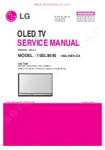
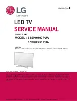
MODEL : 65SK9000PUA
MODEL :
65SK8550PUA
LED TV
SERVICE MANUAL
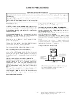
CAUTION
BEFORE SERVICING THE CHASSIS, READ THE SAFETY PRECAUTIONS IN THIS MANUAL.
CONFIDENTIAL
Any reproduction, duplication, distribution (including by way of email, facsimile or other electronic means),
publication, modification, copying or transmission of this Service Manual is STRICTLY PROHIBITED unless you
have obtained the prior written consent of the LG Electronics entity from which you received this Service Manual.
The material covered by this prohibition includes, without limitation, any text, graphics or logos in this Service
Manual.
Copyright © 2018 LG Electronics Inc. All rights reserved. Only training and service purposes.
Summary of Contents for 65SK8550PUA
Page 98: ......