background image

MICROWAVE OVEN

SERVICE MANUAL

MODEL: CC-3082NR

CC-3082NSR

CAUTION

BEFORE SERVICING THE UNIT, READ THE SAFETY PRECAUTIONS IN THIS MANUAL.

Website http://biz.lgservice.com 

P/NO : MFL31706206

October, 2007

Printed in Korea

Internal Use Only

Summary of Contents for CC-3082NR

Page 1: ...VICE MANUAL MODEL CC 3082NR CC 3082NSR CAUTION BEFORE SERVICING THE UNIT READ THE SAFETY PRECAUTIONS IN THIS MANUAL Website http biz lgservice com P NO MFL31706206 October 2007 Printed in Korea 삼 흥 정 판 Internal Use Only ...

Page 2: ... latches 5 evidence of dropping or abuse C Before turning on microwave power for any service test or inspection within the microwave generating compartments check the magnetron wave guide or transmission line and cavity for proper alignment integrity and connections D Any defective or misadjusted components in the interlock monitor door seal and microwave generation and transmission systems shall ...

Page 3: ...ION 5 1 TOOLS AND MEASURING INSTRUMENTS 5 1 MICROWAVE LEAKAGE TEST 5 1 MEASUREMENT OF MICROWAVE POWER OUTPUT 5 3 DISASSEMBLY AND ADJUSTMENT 5 3 INTERLOCK CONTINUITY TEST 5 7 COMPONENT TEST PROCEDURE 5 8 TROUBLE SHOOTING 5 13 TROUBLE SHOOTING Display shows error mode 5 19 EXPLODED VIEW 6 1 REPLACEMENT PARTS LIST 7 1 CONTENTS LGE Internal Use Only Copyright 2007 LG Electronics Inc All right reserved...

Page 4: ...er throughout the cooking time MED HIGH 720W approx 80 of Full power MEDIUM 540W approx 60 of Full power DEFROST 360W approx 40 of Full power LOW WARM 180W approx 20 of Full power CONVECTION Max 250 C GRILL COMBINATION Owner s manual Cook book Glass turntable Rotating ring Rack Metal Tray Multi Rotisserie Bar Handle 1 1 ITEM MODEL Power Requirement Power Output Microwave Frequency Magnetron Timer ...

Page 5: ...te the magnetron unless it is properly installed Be sure that the magnetron gasket is properly installed around the dome of the tube whenever installing the magnetron 2 1 CAUTIONS Unlike other appliances the microwave oven is high voltage and high current equipment Though it is free from danger in ordinary use extreme care should be taken during repair THE OVEN IS TO BE SERVICED ONLY BY PROPERLY Q...

Page 6: ...ring or after cooking of the Grill and Combination mode This glass is very hot during heater operating 9 Do not operate the oven at microwave and combination mode with Grill rack placed in the cavity when the oven is empty EARTHING INSTRUCTIONS This microwave oven is designed to be used in a fully earthed condition It is imperative therefore to make sure it is properly earthed before servicing WAR...

Page 7: ...peed cook 6 SWEET MENU Used to select the sweet menu 7 CLOCK Used to set the time of day 8 PERSIAN COOK Used to select the persian cook 9 DIAL To select convection temperature change cooking time and weight 10 START QUICK START To quickly set the cooking time directly 11 STOP CLEAR Used to stop oven and clear all entries except time of day Turntable Rotating Ring Safety Door Lock System Rack Oven ...

Page 8: ...ess Dial Stop Clear Select Conv combi Desired cooking level Press Dial Stop Clear Select Keep Warm Desired Warming temp 30 C 90 C Press Dial Desired Warming time Start DesiredConv temp 100 C 250 C Press Dial Desired cooking time Start Stop Clear Select Speed hot air Desired convection temp 100 C 250 C Start Stop Clear Select Speed hot air Desired convection temp 100 C 250 C Press Dial Desired cook...

Page 9: ...y shorting the negative high voltage ACHTUNG RELAY5 6 RELAY 4 RELAY 1 WH 1 3 BL RELAY 6 4 YL BN 5 BK PCB PK RD 8 9 PK SWITCH THERMISTOR 3 RELAY2 RELAY3 WH 1 WH RD RED BK BLACK BN BROWN NOTE THERMAL OVEN YL L INPUT POWER NOISE FILTER BL N BL G Y C1 C3 R L C2 FUSE BN BN 230V T T M O L 1 1 21V F M 0V BL YL R M GRILL HEATER WH BN WH 3 3 BN SWITCH PRIMARY Only Roti MDL BN YL RD CONVECTION HEATER WH WH ...

Page 10: ...UM The micom controller controls the ON OFF time of relay 2 by the applied signal to vary the average output power of microwave oven as POWER LEVEL refer to page 1 1 One complete cycle of relay 2 is 22 seconds WHEN THE DOOR IS OPENED DURING COOKING Both the primary switch and relay 2 are cut off primary winding voltage of the high voltage transformer ON OFF of relay 2 is coupled electrically with ...

Page 11: ...nter of the turntable Set the energy leakage monitor to 2 450 MHz and use it following the manufacturer s recommended test procedure to assure correct result When measuring the leakage always use the 2 inch 5cm spacer supplied with the probe Operate the oven at its maximum output Measure the microwave radiation using and electromagnetic radiation monitor by holding the probe perpendicular to the s...

Page 12: ... sec along the shaded area otherwise a false reading may result The test probe must be held with the grip portion of the handle A false reading may result if the operator s hand is between the handle and the probe When testing near a corner of the door keep the probe perpendicular to the surface making sure the probe is moved horizontally along the oven surface this may possibly cause probe damage...

Page 13: ...f bowl is measured while the microwave generator is operating at full power Magnetron filament heat up time is not included The water is stirred to equalize temperature throughout the vessel prior to measuring the final water temperature Stirring devices and measuring instruments are selected in order to minimize addition or removal of heat WATER LOAD TURNTABLE MEASUREMENT OF MICROWAVE POWER OUTPU...

Page 14: ...rom lamp 2 Remove the mounting screw to the cavity G MAGNETRON REMOVAL 1 Disconnect the leadwire from the high voltage transformer and high voltage capacitor 2 Carefully remove the mounting screws holding the magnetron and the waveguide 3 Remove the magnetron ASS Y until the tube is clear from the waveguide NOTE 1 When removing the magnetron make sure its dome does not hit any adjacent parts or it...

Page 15: ...ormer and capacitor 3 Remove the screw holding the high voltage transformer to the baseplate K THE TURNTABLE MOTOR REMOVAL 1 Remove the turntable 2 Remove the turntable shaft VERY CAREFULLY with a slotted screwdriver 3 Lay the unit down on its back 4 Remove the turntable motor cover The turntable base cover is easily removed by pinching the eight parts with a wire cutting 5 Disconnect the leadwire...

Page 16: ...hanism is a device which has been specially designed to eliminate microwave activity when the door is opened during cooking and thus to prevent the danger resulting from the microwave leakage 2 MOUNTING OF THE PRIMARY MONITOR SECONDARY SWITCHES TO THE LATCH BOARD 3 INSTALLATION AND ADJUSTMENT OF THE LATCH BOARD TO THE OVEN ASSEMBLY Mount the latch board to the oven assembly Adjust the latch board ...

Page 17: ... make the necessary adjustment or replace the switch only with the same type of switch C MONITOR SWITCH TEST Disconnect the wire lead from the monitor switch Connect the ohmmeter leads to the common COM and normally closed NC terminals of the switch The meter should indicate closed circuit in the door open condition When the door is closed meter should indicate an open circuit When the monitor swi...

Page 18: ...TRON Wire leads removed 1 Measure the resistance Ohm meter scale Rx1 and Rx100 Primary winding Secondary winding Filament winding 2 Measure the resistance Ohm meter scale Rx1000 Primary winding to ground Filament winding to ground 1 Measure the resistance Ohm meter scale Rx1 Filament terminal 2 Measure the resistance Ohm meter scale Rx1000 Filament to chassis Approx 2 0 ohm Approx 150 ohm Less tha...

Page 19: ...le Rx10000 Measure the continuity Reverse Ohm meter scale Rx10000 Normal Momentarily indicates several ohms and then gradually returns to infinite Normal Infinite Normal Continuity Abnormal Infinite Normal Infinite Abnormal Continuity NOTE When testing the magnetron be sure to install the magnetron gasket in the correct position and be sure that the gasket is in good condition Antenna Gasket Chass...

Page 20: ...h and the fuse at the same time Replace just the fuse if the switches operate normally NOTE Make sure heater is fully cooled when tested Measure the resistance Multi meter scale Rx1 Normal Grill heater Approx 42 ohm at 20 30o C Convection heater Approx 63 ohm at 20 30o C Normal more than 0 5 Mohm Normal Abnormal Measure the resistance with 500V 100M ohm insulation resistance meter 0 C Approx 60 C ...

Page 21: ...OTOR Wire leads removed Measure the resistance Ohm meter scale R x 1 Measure the resistance Ohm meter scale R x 1000 Check for P C B connector Normal Approx 300 500 ohm Abnormal Infinite or several ohm Normal Approx 10 20 kohm Abnormal Infinite or several ohm B Cooking Start OFF Relay 2 Relay 3 Relay 5 1 2 3 4 5 6 7 8 9 Cooking Start OFF LGE Internal Use Only Copyright 2007 LG Electronics Inc All ...

Page 22: ...THE UNIT IS SERVICED FOR ANY REASON MAKE SURE THE WIRE LEADS ARE CORRECT POSITION WHEN REMOVING THE WIRE LEAD FROM THE PARTS BE SURE TO GRASP THE CONNECTOR NOT THE WIRES Normal COM 230V Approx 160 Ω Abnormal Infinite or several ohm LGE Internal Use Only Copyright 2007 LG Electronics Inc All right reserved Only for training and service purposes ...

Page 23: ...ONDITION Microwave oven does not work Inserting many plug into one plug outlet and using them at the same time causes overloading Microwave oven plug is not inserted tightly Output power is too low Low AC input voltage Food temperature is too low Using metallic ware and allowing it to touch the oven wall Sparks occurring Inconsistent intensity of microwave by their characteristics 1 Wrap the thinn...

Page 24: ...ator light does not turn on after setting cooking cycle 11 Display time of day does not reappear when cooking is finished 12 Beep sound is not heard when correct key is touched 5 14 TROUBLE 1 The following visual conditions indicate a probable defective control circuit CONDITION CHECK RESULT CAUSE REMEDY Everything works as specified Still have trouble Defective key membrane assembly Defective PCB...

Page 25: ...th door opened Disconnect one side of the wire lead connected from transformer to the high voltage capacitor and operate the unit Replace fuse TROUBLE 2 Oven does not operate at all Display window does not display any figures and no input is accepted NOTE All these switches must be replaced at the same time Refer to page 5 6 5 7 2 Fuse does not blow No continuity No continuity Replace power supply...

Page 26: ... Abnormal Normal Defective fan motor Defective oven lamp Replace fan motor Replace oven lamp Loose connection Connection then tightly CONDITION CHECK RESULT CAUSE REMEDY Output is low Lower than 90 of rating voltage Normal Normal Abnormal Abnormal Measure the output power Disconnect the wire leads from relay 2 and check on and off time with multitester Defective P C B assembly Replace P C B assemb...

Page 27: ...transformer Check H V transformer normal normal Abnormal Defective high voltage Diode Replace high voltage Diode Check H V diode Abnormal Defective high voltage capacitor Replace high voltage capacitor Check H V capacitor Abnormal Defective magnetron Replace magnetron Check Magnetron TROUBLE 5 No microwave oscillation even though oven lamp and fan motor run Display operates properly LGE Internal U...

Page 28: ...ok properly when programmed for the set power level Operates properly on HIGH CONDITION CHECK RESULT CAUSE REMEDY Output is full when you set lower power level Abnormal Disconnect the wire leads from relay 2 and check continuity relay 2 Operate the unit Defective P C B assembly Replace P C B assembly NOTE Make sure the wire leads are in the correct position When removing the wire leads from parts ...

Page 29: ...ace the P C B assembly CONDITION CHECK RESULT CAUSE REMEDY Display shows E02 No continuity Continuity Normal Abnormal Check the thermistor Defective thermistor Thermistor opened Replace the thermistor Loose connection Connect them tightly Check the connnection between Thermistor and P C B assembly Normal Abnormal Check the heater Defective heater Heater opened Replace the heater Defective P C B As...

Page 30: ... 6 8 DOOR PARTS CONTROL PANEL PARTS OVEN CAVITY PARTS LATCH BOARD PARTS BASE PLATE PARTS INTERIOR PARTS EXPLODED VIEW INTRODUCTION EV MODEL ...

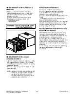
Page 31: ... 6 9 13552A 13581A 14026A 14970A 13213A 13551A 13806A WTP037 WTP013 13650A DOOR PARTS EV ...

Page 32: ... 6 10 24781S 23572A 23550F 268712 268711 WTP004 WTP018 23550D 249401 243501 25020M 25020S CONTROL PANEL PARTS EV ...

Page 33: ...0A 36549S WTP013 33112U WTT021 WTT010 33052M 34930R 34960R 343501 34370Z 348102 56930V 35300A 948501 948502 348101 WTT021 WNH001 WNH001 WSZ232 33301L 33301R 34270A 34271A 33650T 35264A WTP013 36549R 34810R WTT029 34930W WTT029 OVEN CAVITY PARTS EV ...

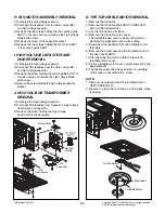
Page 34: ... 6 12 WSZ085 43501A 466001 43500A 466003 44510A 466001 LATCH BOARD PARTS EV ...

Page 35: ...6411A WSZ062 50FZZA 56201A 54974S WTT037 WSZ002 WTT028 WSZ002 50CZZH 56549F 56851C 54810C 56324A 55262A 56912B 55900A WSZ002 WTT021 WTT021 WTT028 568772 55238A WTT021 54975G WNH200 WWS005 WTT021 54810S 55300S WTT021 WNZ015 535041 56208A 535042 36549C WNZ015 55900C INTERIOR PARTS EV ...

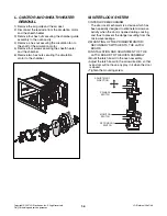
Page 36: ... 6 14 63302A 63303A 56170D 647781 WTT030 WTT028 WTT021 WSZ002 BASE PLATE PARTS EV ...

Page 37: ......

Reviews: