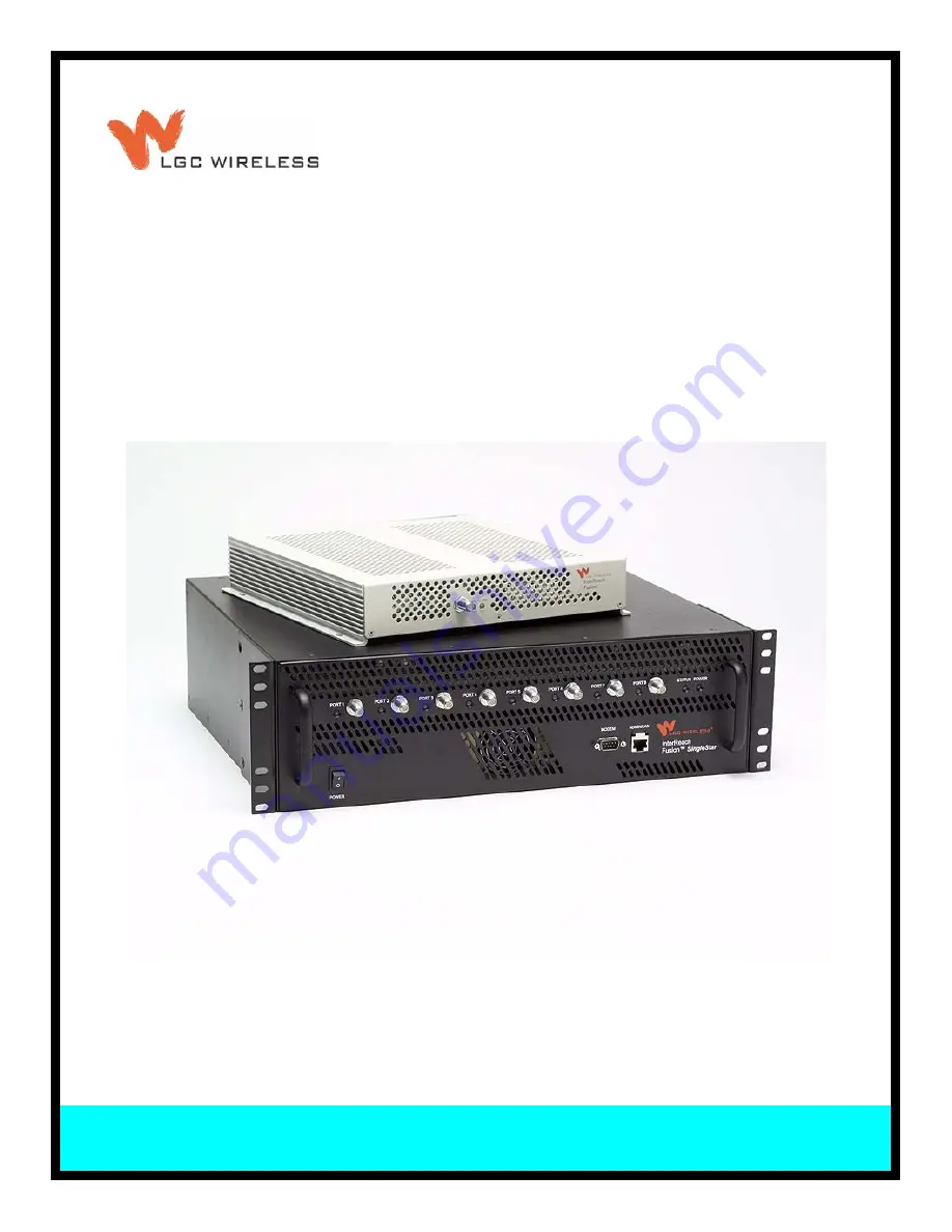
background image

D-620605-0-20

Rev A

Installation, Operation, and Reference Manual

InterReach Fusion

TM

 SingleStar

®

Summary of Contents for InterReach Fusion SingleStar

Page 1: ...D 620605 0 20 Rev A Installation Operation and Reference Manual InterReach Fusion TM SingleStar ...

Page 2: ...D 620605 0 20 Help Hot Line U S only 1 800 530 9960 Rev A CONFIDENTIAL ...

Page 3: ...ance on the material as presented including but not limited to typographical and listing errors Your comments are welcome they help us improve our products and documentation Please address your comments to LGC Wireless Inc corporate headquarters in San Jose California Address 2540 Junction Avenue San Jose California 95134 1902 USA Attn Marketing Dept Phone 1 408 952 2400 Fax 1 408 952 2410 Help Ho...

Page 4: ...d to Seller transportation and other applicable charges prepaid by the Purchaser and d Seller s examination of such Goods discloses to its reasonable satisfaction that defects were not caused by negligence misuse improper installation improper maintenance accident or unauthorized repair or alteration or any other cause outside the scope of Purchaser s warranty made hereunder Notwithstanding the fo...

Page 5: ...ties Overview 2 4 2 2 1 System Monitoring and Reporting 2 5 2 2 2 Using Alarm Contact Closures 2 5 2 3 System Connectivity 2 6 2 4 System Operation 2 7 2 5 System Specifications 2 8 2 5 1 RF End to End Performance 2 9 SECTION 3 Fusion SingleStar Hub 3 1 3 1 Fusion SingleStar Hub Front Panel 3 3 3 1 1 F Connectors 3 4 3 1 2 Communications RS 232 Serial Connector 3 4 3 1 3 Hub LED Indicators 3 4 3 2...

Page 6: ... 13 5 4 1 Path Loss Equation 5 14 5 4 2 RAU Coverage Distance 5 15 5 4 3 Examples of Design Estimates 5 19 5 5 Designing for a Neutral Host System 5 22 5 6 Connecting a Hub to a Base Station 5 23 5 6 1 Uplink Attenuation 5 23 5 6 2 RAU Attenuation and ALC 5 24 SECTION 6 Installing Fusion SingleStar 6 1 6 1 Installation Requirements 6 1 6 1 1 Component Location Requirements 6 2 6 1 2 Cable and Conn...

Page 7: ...nder Connection 6 41 6 7 4 POTS Line Sharing Switch Connection 6 42 6 7 5 Ethernet LAN Connection 6 44 6 7 6 SNMP Interface 6 45 SECTION 7 Replacing Fusion SingleStar Components 7 1 7 1 Replacing an RAU 7 1 7 2 Replacing a Fusion SingleStar Hub 7 2 SECTION 8 Maintenance Troubleshooting and Technical Assistance 8 1 8 1 Service 8 1 8 2 Maintenance 8 1 8 3 Troubleshooting 8 2 8 3 1 Troubleshooting Us...

Page 8: ...CONFIDENTIAL iv InterReach Fusion SingleStar Installation Operation and Reference Manual D 620605 0 20 Rev A ...

Page 9: ...0 Figure 6 2 Mounting of Rack Mounting Brackets for Hub Wall Mounting 6 12 Figure 6 3 800 850 MHz Spectrum 6 16 Figure 6 4 Guideline for Unison RAU Antenna Placement 6 16 Figure 6 5 Connection Settings Dialog Box 6 20 Figure 6 6 System Configuration Window 6 21 Figure 6 7 Simplex Base Station to a Fusion SingleStar Hub 6 23 Figure 6 8 Duplex Base Station to a Fusion SingleStar Hub 6 24 Figure 6 9 ...

Page 10: ...apter Cable 6 38 Figure 6 20 OA M Direct Connection 6 39 Figure 6 21 OA M Modem Connection 6 40 Figure 6 22 OA M Connection using a 232 Port Expander 6 41 Figure 6 23 OA M Connection Using a POTS Line Sharing Switch 6 42 Figure 6 24 Cascading Line Sharing Switches 6 43 Figure 6 25 OA M Connection Using Ethernet and ENET 232 Serial Hub 6 44 Figure 6 26 Fusion SingleStar SNMP Configuration Options 6...

Page 11: ...ED States 3 6 Table 3 3 9 pin D sub Pin Connector Functions 3 8 Table 3 4 Fusion SingleStar Hub Specifications 3 11 Table 4 1 Frequency Bands Covered by Fusion RAUs 4 3 Table 4 2 Remote Access Unit LED States 4 4 Table 4 3 Remote Access Unit Specifications 4 5 Table 5 1 Cellular Power per Carrier 5 5 Table 5 2 GSM EGSM and EDGE Power per Carrier 5 6 Table 5 3 DCS Power per Carrier 5 7 Table 5 4 PC...

Page 12: ...for Component Installation 6 7 Table 6 4 Optional Accessories for Component Installation 6 7 Table 6 5 Troubleshooting Fusion SingleStar Hub LEDs During Installation 6 13 Table 6 6 Troubleshooting RAU LEDs During Installation 6 18 Table 6 7 Alarm Types 6 32 Table 8 1 Faults Reported by the Fusion SingleStar Hub 8 5 Table 8 2 Faults Reported by the RAU 8 11 Table 8 3 Warnings Reported by the Fusion...

Page 13: ... 0 20 Rev A CONFIDENTIAL SECTION 1 General Information This section contains the following subsections Section 1 1 Firmware Release 1 2 Section 1 2 Purpose and Scope 1 2 Section 1 3 Conventions in this Manual 1 3 Section 1 4 Standards Conformance 1 4 Section 1 5 Related Publications 1 4 ...

Page 14: ...ons and unit specifications Section 5 Designing a Fusion SingleStar Solution This section provides tools to aid you in designing your Fusion SingleStar system including tables of the maximum output power per carrier at the RAU and formu las and tables for calculating path loss coverage distance and link budget Section 6 Installing Fusion SingleStar This section provides installation procedures req...

Page 15: ...tain information as described NOTE This format emphasizes text with special significance or impor tance and provides supplemental information CAUTION This format indicates when a given action or omitted action can cause or contribute to a hazardous condition Damage to the equipment can occur WARNING This format indicates when a given action or omitted action can result in catastrophic damage to th...

Page 16: ...nual CONFIDENTIAL D 620605 0 20 Rev A 1 4 Standards Conformance Fusion SingleStar uses the TIA EIA 568 and 570 cabling standards for ease of installation Refer to Appendix B for compliance information 1 5 Related Publications AdminBrowser User Manual LGC Wireless part number D 620607 0 20 Rev A ...

Page 17: ...atic gain control ability to incrementally adjust down link uplink gain end to end alarming of all components and the associated cable infrastructure and a host of additional capabilities The Fusion SingleStar system supports major wireless standards and air interface pro tocols in use around the world including Frequencies 800 MHz 850 MHz 900 MHz 1800 MHz 1900 MHz 2100 MHz Voice Protocols AMPS TD...

Page 18: ...G 11 Flexible RF configuration capabilities including System gain Ability to manually set gain in 1 dB steps from 0 to 15 dB on both down link and uplink RAU RAU uplink and downlink gain can be independently attenuated 10 dB in 1 dB steps Uplink level control protects the system from input overload and can be optimized for either a single operator or multiple operators protocols VSWR check on RAU ...

Page 19: ...ace to RF source Periodically polls all downstream RAUs for system status and automatically reports any fault or warning conditions Supplies DC power to RAUs over CATV cable Remote Access Unit RAU Converts IF signals to RF on the downlink RF to IF on the uplink Microprocessor controlled for alarms monitoring and control Multi band protocol independent frequency specific units The minimum configura...

Page 20: ...Hub s front panel RJ 45 port connects directly to a PC for local Ethernet access The Hub s front panel RS 232 serial port connects directly to a modem for remote access Remote access is also available with an optional 100BASE T LAN switch con nections to the RJ 45 port Figure 2 2 Three Methods for OA M Communications AdminBrowser OA M software runs on the Fusion SingleStar Hub microprocessor and c...

Page 21: ...sures You can connect the DB 9 female connector on the rear panel of the Fusion Single Star Hub to a local base station or to a daisy chained series of Fusion Unison LGCell and or MetroReach Focus systems When you connect MetroReach Focus or a BTS to the Fusion SingleStar the Fusion SingleStar Hub outputs the alarms alarm source and MetroReach Focus or the BTS receives the alarms alarm sense This ...

Page 22: ... 2 3 System Connectivity The system uses standard 75 Ohm CATV cable This makes any system expansion such as adding an extra antenna for additional coverage as easy as pulling thin Ether net cable Figure 2 4 Fusion SingleStar s Architecture InterReach CATV CATV CATV up to 8 RAUs per Hub RAU RAU RAU Fusion SingleStar RG 59 6 or 11 ...

Page 23: ...he Hub converts the RF signals to IF signals and sends them to RAUs up to 8 using CATV cable The RAU converts the IF signals to RF and sends them to passive antennas using coaxial cable Fusion SingleStar Hub RAU The Fusion SingleStar Hub sends the RF signals to a base station using coaxial The Hub receives the IF signals from the RAUs up to 8 using CATV cable and con verts them to RF signals The R...

Page 24: ...rt Link RAU Unit Status 1 pair Link Alarm AC Power Volts Rating 115 230V 6 3A 50 60 Hz Operating Range 90 132V 170 250V auto ranging DC Power Volts 54V from the Hub Power Consumption W 4 RAUs 350 typical 8 RAUs 5300 typical 64 max from the Hub Enclosure Dimensions height width depth Excluding angle brackets for 19 rack mounting of hub The Fusion SingleStar Hub s typical power consumption assumes t...

Page 25: ...869 894 824 849 1900 1930 1990 1850 1910 900 1800 FSN 9018 1 900 925 960 880 915 1800 1805 1880 1710 1785 900 2100 FSN 9021 1 900 925 960 830 715 Table 2 4 850 MHz RF End to End Performance Parameter Typical Downlink Uplink Average gain with 75 m RG 59 at 25 C 77 F dB 15 15 Ripple with 150 m RG 59 dB 2 5 3 Output IP3 dBm 38 Input IP3 dBm 5 Output 1 dB Compression Point dBm 26 Noise Figure 1 Hub 8 ...

Page 26: ...26 Noise Figure 1 Hub 8 RAUs dB 16 Table 2 7 1800 MHz RF End to End Performance Typical Parameter Downlink Uplink Average gain with 75 m RG 59 at 25 C 77 F dB 15 15 Downlink ripple with 75 m Cat 5 5E 6 dB 2 Uplink ripple with 75 m RG 59 dB 2 Uplink gain roll off with 75 m RG 59 dB Outside the center 60 MHz 2 Output IP3 dBm 38 Input IP3 dBm 12 Output 1 dB Compression Point dBm 26 Noise Figure 1 Hub...

Page 27: ... Performance Parameter Typical Downlink Uplink Average gain w 75 meters RG 59 25 C dB 15 15 Ripple with 75 m RG 59 dB 2 5 4 Spurious Output Levels dBm 30 UMTS TDD Band Spurious Output Level 1900 1920 MHz 2010 2025 MHz dBm MHz 52 Output IP3 dBm 37 Input IP3 dBm 12 Output 1 dB Compression Point dBm 26 Noise Figure 1 Hub 8 RAUs dB 17 ...

Page 28: ...System Specifications 2 12 InterReach Fusion SingleStar Installation Operation and Reference Manual CONFIDENTIAL D 620605 0 20 Rev A This page is intentionally left blank ...

Page 29: ... rack and is usually collocated with the RF source in a telecommunications closet Downlink Path The Fusion SingleStar Hub receives downlink RF signals from each RF source RF1 RF2 using coaxial cable It converts the signals to IF and sends them to up to eight RAUs using CATV cable The Hub also sends OA M communication to the RAUs using the CATV cable Uplink Path The Fusion SingleStar Hub receives u...

Page 30: ...3 2 InterReach Fusion SingleStar Installation Operation and Reference Manual CONFIDENTIAL D 620605 0 20 Rev A Figure 3 1 Fusion SingleStar Hub Block Diagram ...

Page 31: ...TV cable F connectors labeled PORT 1 2 3 4 5 6 7 8 3 One pair of unit status LEDs One LED for unit power status labeled POWER One LED for unit status labeled STATUS 4 One 9 pin D sub male connector for system remote dial up communication and diagnostics using a modem labeled MODEM 5 One RJ 45 female connector for system communication and diagnostics using a PC laptop with direct connect or using a...

Page 32: ...9 female and a DB 25 male connector Refer to Appendix A 3 on page A 3 for the cable pinout Remote monitoring is also available by connecting the RJ 45 ADMIN LAN port to a LAN switch for remote Ethernet LAN access or direct dial up router access Local Monitoring Use a crossover Ethernet cable to connect a laptop or PC to the RJ 45 female connec tor for local monitoring or configuring using the Admi...

Page 33: ...tus LEDs labeled POWER and STATUS which can be in one of the states shown in Table 3 1 These LEDs can be steady green steady red orange There is no off state when the unit s power is on Table 3 1 Fusion SingleStar Hub Status LED States LED State Indicates Green Green The Hub is connected to power and all power supplies are operating The Hub is not reporting a fault however the system test may need...

Page 34: ...able 3 2 These LEDs can be off steady green flashing red 60 pulses per minute PPM Table 3 2 Fusion SingleStar Hub Port LED States LED State Indicates Off The RAU is not connected Green The RAU is connected No faults from the RAU Red 60 PPM The RAU was disconnected The RAU is not communicating The RAU port power is tripped 54 VDC is shutdown due to an EH over temperature condition Red Steady The RA...

Page 35: ...ion SingleStar Hub Rear Panel 1 AC power cord connector 2 Two air exhaust vents 3 Two N type female connectors fore each band Band 1 and Band 2 Uplink labeled UL 1 and UL 2 Downlink labeled DL 1 and DL 2 4 One 9 pin D sub female connector for contact alarm monitoring labeled ALARMS 5 Ground lug for connecting unit to frame ground labeled GROUND 1 4 2 2 3 3 5 ...

Page 36: ...3 2 1 2 N type Female Connectors There are two N type female connectors on the rear panel of the Hub The DOWNLINK connector receives downlink RF signals from a repeater local base station or MetroReach Focus system The UPLINK connector transmits uplink RF signals to a repeater local base sta tion or MetroReach Focus system CAUTION The UPLINK and DOWNLINK ports cannot handle a DC power feed from th...

Page 37: ...cting Warnings indicate a possible service impact Status messages are generally not service impacting The Fusion SingleStar Hub periodically queries attached Remote Access Units for their status Both faults and warnings are reported to a connected PC laptop running a standard browser communicating with the AdminBrowser software Only faults are indicated by LEDs For more information regarding the e...

Page 38: ...ired choice After you click OK AdminBrowser refreshes and updates the tree view according to the new setting NOTE The setting is strictly visual and only in AdminBrowser There is no affect on the hardware itself By default the event filtering is set to Enable viewing of Faults only The only exception when the event filtering is ignored is during the Install Configure command All events are display...

Page 39: ...ernal Alarm Connector contact closure 1 9 pin D sub female Maximum 400 mA 60V AC DC Typical 4 mA 12V DC ADMIN LAN Interface Connector 1 RJ 45 female 1 9 pin D sub male for optional modem RF Connectors 4N female 50 ohms 1 Downlink Uplink pair per band 8 F female CATV 75 ohm a a For system performance it is important that you use only 75 Ohm CATV cable with solid copper center conductor LED Fault an...

Page 40: ...Fusion SingleStar Hub Specifications 3 12 InterReach Fusion SingleStar Installation Operation and Reference Manual CONFIDENTIAL D 620605 0 20 Rev A This page is intentionally left blank ...

Page 41: ...the site where RF is to be delivered Downlink Path The RAU receives downlink IF signals from a Fusion SingleStar Hub using CATV cable It converts the signals to RF and sends them to a passive RF antenna using coaxial cable Also the RAU receives configuration information from the Fusion SingleStar Hub using the CATV cable Uplink Path The RAU receives uplink RF signals from a passive RF antenna usin...

Page 42: ...4 2 InterReach Fusion SS Installation Operation and Reference Manual CONFIDENTIAL D 620605 0 20 Rev A Figure 4 1 Remote Access Unit Block Diagram ...

Page 43: ...ductor cables NOTE For system performance it is important that you use only low loss solid copper center conductor CATV cable with quality F connectors that use capture centerpin conductors Refer to Appendix A for more information 4 2 RAU LED Indicators Upon power up the RAU goes through a two second test to check the LED lamps During this time the LEDs blink green green red red letting you visual...

Page 44: ...tion refer to page 8 11 for RAU faults page 8 14 for RAU warnings page 8 17 for RAU status messages Table 4 2 Remote Access Unit LED States LED State Indicates Off Off The RAU is not receiving DC power Green Green The RAU is powered and is not indicating a fault condition Communication with the Fusion SingleStar Hub is normal however the system test may need to be performed or a warning condition ...

Page 45: ... to Appendix A for more information Table 4 3 Remote Access Unit Specifications Specification Description Dimensions H W D 133 5 mm 438 mm 381 mm 5 25 in 17 25 in 15 in Weight 2 1 kg 4 6 lb Operating Temperature 25 to 45 C 13 to 113 F Non operating Temperature 25 to 85 C 13 to 185 F Operating Humidity non condensing 5 to 95 RF Connectors 1 F female CATV 75 ohms 1 N female coaxial 50 ohms LED Alarm...

Page 46: ...Remote Access Unit Specifications 4 6 InterReach Fusion SS Installation Operation and Reference Manual CONFIDENTIAL D 620605 0 20 Rev A ...

Page 47: ...et for example 85 dBm The design goal is always a stronger signal than the mobile phone needs It includes inherent factors which affect performance RF source base station or BDA type of equipment if possible 2 Determine the downlink power per carrier from the RF source through the DAS Refer to Section 5 2 Maximum Output Power per Carrier on page 5 4 The maximum power per carrier is a function of m...

Page 48: ...3 Use the path loss slope PLS which gives a value to the RF propagation charac teristics within the building to convert the RF link budget into an estimate of the coverage distance per antenna This helps establish the quantities of Fusion Sin gleStar equipment you need The actual path loss slope that corresponds to the specific RF environment inside the building can also be determined empirically ...

Page 49: ...mal shadow fading slow or large scale are determined by the desired confidence factor and other factors Downlink RSSI design goal calculations for the TDMA protocol are shown below for a 95 area cov erage confidence factor Downlink design goals on the order of 85 dBm are typical for protocols such as GSM and iDEN Wireless service providers may choose a higher level to ensure that in building signa...

Page 50: ...degraded and or regula tor requirements will be violated The maximum input power to the Hub is deter mined by subtracting the system gain from the maximum output power of the RAU System gain is software selectable from 0 dB to 15 dB in 1 dB steps Additionally both the uplink and downlink gain of each RAU can be reduced by 10 dB in 1 dB steps When connecting a Hub to a base station or repeater atte...

Page 51: ...11 5 11 5 11 8 4 13 5 13 10 0 10 0 10 0 6 5 5 12 0 11 5 9 0 9 0 9 0 5 0 6 10 5 10 5 8 5 8 5 8 0 7 9 5 9 5 8 0 8 0 7 5 8 8 5 8 5 7 5 7 5 7 0 9 8 0 8 0 7 0 7 0 10 7 0 7 5 6 5 6 5 11 7 0 7 0 6 5 6 5 12 6 5 6 5 6 0 6 0 13 6 0 6 5 6 5 5 5 14 5 5 6 0 5 5 5 5 15 5 5 5 5 5 0 5 0 16 5 0 5 5 5 0 5 0 20 4 0 4 5 4 5 4 0 30 2 0 2 5 3 0 2 0 Note Operation at or above these output power levels may prevent Fusion...

Page 52: ...ier No of Carriers Power per Carrier dBm GSM EDGE 1 16 0 16 0 2 13 0 13 0 3 11 0 11 0 4 10 0 10 0 5 9 0 9 0 6 8 0 8 0 7 7 5 7 5 8 7 0 7 0 9 6 5 6 5 10 6 0 6 0 11 5 5 5 5 12 5 0 5 0 13 5 0 5 0 14 4 5 4 5 15 4 0 4 0 16 4 0 4 0 20 3 3 30 1 1 Note Operation at or above these output power levels may prevent Fusion SingleStar from meeting RF performance specifications or FCC Part 15 and EN55022 emission...

Page 53: ...r dBm GSM EDGE 1 16 5 16 5 2 14 5 14 5 3 12 5 12 5 4 11 5 11 5 5 10 5 10 5 6 9 5 9 5 7 9 0 9 0 8 8 5 8 0 9 8 0 7 5 10 7 5 7 0 11 7 0 6 5 12 6 5 6 0 13 6 5 6 0 14 6 0 5 5 15 5 5 5 0 16 5 5 5 0 20 4 5 4 0 30 2 5 2 0 Note Operation at or above these output power levels may pre vent Fusion SingleStar from meeting RF performance specifica tions or FCC Part 15 and EN55022 emissions requirements ...

Page 54: ...2 16 5 15 5 15 5 13 0 11 0 3 15 0 13 5 13 5 11 0 8 0 4 13 0 12 0 12 0 10 0 6 5 5 11 5 11 0 10 5 9 0 5 0 6 10 5 10 5 9 5 8 0 7 9 5 10 0 9 0 7 5 8 8 5 9 0 8 0 7 0 9 8 0 8 5 7 5 10 7 5 8 0 7 0 11 7 0 7 5 6 5 12 6 5 7 0 6 0 13 6 5 6 5 6 0 14 6 0 6 5 5 5 15 5 5 6 0 5 0 16 5 5 5 5 5 0 20 4 5 4 5 4 0 30 2 5 3 0 2 0 Note Operation at or above these output power levels may prevent Fusion SingleStar from me...

Page 55: ...5 UMTS Power per Carrier No of Carriers Power per Carrier dBm WCDMA 1 15 0 2 11 0 3 8 0 4 6 5 5 5 0 6 4 0 7 3 0 Note measurements taken with no baseband clipping Note Operation at or above these output power levels may prevent Fusion SingleStar from meeting RF performance specifications or FCC Part 15 and EN55022 emissions requirements ...

Page 56: ... four RF carri ers This will likely result in additional RAUs 2 Design the initial coverage for two RF carriers but reserve RAU ports on the Hub for future use These ports can be used to fill potential coverage holes once the power per carrier is lowered to accommodate the two additional carriers Table 5 6 Paging SMR Power per Carrier No of Carriers Power per Carrier dBm iDEN Analog FM CQPSK C4FM ...

Page 57: ...s 492 ft For RG 6 cable 200 meters 656 ft For RG 6 cable 300 meters 984 ft If the system is operated with CATV cable less than 10 meters 33 ft in length sys tem performance will be greatly compromised If the CATV cable is longer than the recommended distance per cable type the gain of the system will decrease as shown in Table 5 7 Table 5 7 System Gain Loss Relative to CATV Cable Length Typical ch...

Page 58: ...ngleStar Installation Operation and Reference Manual CONFIDENTIAL D 620605 0 20 Rev A 200 m 5 3 4 1 220 m 7 5 5 8 240 m 9 7 7 6 Table 5 7 System Gain Loss Relative to CATV Cable Length Typical change in system gain dB RG 59 Downlink Uplink ...

Page 59: ...ing APL between the Antenna and the Wireless Device APL P Lcoax G RSSI 1 where APL the maximum allowable path loss in dB P the power per carrier transmitted by the RAU in dBm Lcoax the coaxial cable loss between the RAU and passive antenna in dB G the gain of the passive antenna in dBi Coaxial cable is used to connect the RAU to an antenna Table 5 8 lists coaxial cable loss for various cable lengt...

Page 60: ...ormal random variable that depends on partition material and geome tries inside the building and is accounted for by the log normal fade margin used in the downlink RSSI design goal calculation As a reference Table 5 9 provides estimates of signal loss for some RF barriers1 1 Rappaport Theodore S Wireless Communications Principles and Practice Prentice Hall PTR 1996 Table 5 9 Average Signal Loss o...

Page 61: ... as 10n Equation 2 can be simplified to PL d 20log10 4πf c PLS log10 d 3 Table 5 10 gives the value of the first term of Equation 3 that is 20log10 4πf c for various frequency bands Table 5 10 Frequency Bands and the Value of the First Term in Equation 3 Frequency Band MHz Mid Band Frequency MHz 20log10 4πf c Uplink Downlink 850 MHz Cellular 824 849 869 894 859 31 1 900 MHz GSM 890 915 935 960 92 ...

Page 62: ... 5 11 Estimated Path Loss Slope for Different In Building Environments Environment Type Example PLS for 800 850 900 MHz PLS for 1800 1900 MHz Open Environment very few RF obstructions Parking Garage Convention Center 33 7 30 1 Moderately Open Environment low to medium amount of RF obstructions Warehouse Airport Manufacturing 35 32 Mildly Dense Environment medium to high amount of RF obstructions R...

Page 63: ... for spread spectrum protocols Table 5 12 Approximate Radiated Distance from Antenna for 850 MHz Cellular Applications Environment Type Distance from Antenna Meters Feet Open Environment 73 241 Moderately Open Environment 63 205 Mildly Dense Environment 55 181 Moderately Dense Environment 47 154 Dense Environment 39 129 Table 5 13 Approximate Radiated Distance from Antenna for 900 MHz GSM Applicat...

Page 64: ...nna Meters Feet Open Environment 70 231 Moderately Open Environment 60 197 Mildly Dense Environment 53 174 Moderately Dense Environment 45 149 Dense Environment 38 125 Table 5 15 Approximate Radiated Distance from Antenna for 1800 MHz DCS Applications Facility Distance from Antenna Meters Feet Open Environment 75 246 Moderately Open Environment 58 191 Mildly Dense Environment 50 166 Moderately Den...

Page 65: ...recommended maximum power per carrier of 7 5 dBm The input power should be set to the desired output power minus the system gain 3 Link Budget In this example a design goal of 85 dBm is used Suppose 3 dBi omni directional antennas are used in the design Then the maximum RF propa gation loss should be no more than 95 5 dB 7 5 dBm 3 dBi 85 dBm over Table 5 16 Approximate Radiated Distance from Anten...

Page 66: ... estimation For this case assume a circular radiation pattern though the actual area covered will depend upon the pattern of the antenna and the obstructions in the facility 6 Equipment Required Since you know the building size you can now estimate the Fusion SingleStar equipment quantities needed Before any RF levels are tested in the building you can estimate that two antennas per level will be ...

Page 67: ...tion loss should be no more than 89 0 dB 11 0 dBm 3 dBi 75 dBm over 95 of the area being covered It is important to note that a design goal such as 75 dBm is usually derived taking into account multipath fading and log normal shadowing characteristics Thus this design goal will only be met on average over 95 of the area being covered At any given point a fade may bring the sig nal level underneath...

Page 68: ...valuation is required to accurately establish the Fusion SingleStar equipment quantities required for the building The site survey measures the RF losses within the building to determine the actual PLS which will be used in the final path loss formula to determine the actual requirements of the Fusion SingleStar system 5 5 Designing for a Neutral Host System A neutral host system supports more tha...

Page 69: ...eStar not by the attenuator However some base stations trigger alarms if the noise or signal levels are too high In this case the attenuation must be large enough to prevent this from happening CAUTION The UPLINK and DOWNLINK ports cannot handle a DC power feed from a BTS If DC power is present a DC block must be used or the Fusion SingleStar hub may be damaged If in an area covered by Fusion Sing...

Page 70: ...ach band s uplink RF input and if that level exceeds 30 dBm an RF attenuator is activated The level of attenuation is equal to the amount that the input exceeds 30 dBm The following sequence describes the operation of the ALC circuit as illustrated in Figure 5 2 1 The RF signal level into either Band of the RAU rises above the activation thresh old 30 dBm causing that ALC loop to enter into the at...

Page 71: ...nsitiv ity is reduced and mobile phones in the area of that RAU band will have to trans mit at a higher power This would increase interference to the outdoor network from such mobiles Uplink Attenuation The uplink attenuator attenuates environmental noise picked up by an RAU band located in an area where heavy electrical machinery is operat ing In such environments the electrical noise can be quit...

Page 72: ...le or multiple wireless devices in very close proximity to the RAU band Compression causes signal degradation and ultimately dropped calls and data errors and should be prevented Two settings are available to optimize UL ALC performance Multiple Operators Use when more than one operator and or protocol is present in the Fusion SingleStar system s band frequency or adjacent frequency bands This set...

Page 73: ...Help Hot Line U S only 1 800 530 9960 5 27 D 620605 0 20 Rev A CONFIDENTIAL Connecting a Hub to a Base Station This page is intentionaly left blank ...

Page 74: ...Connecting a Hub to a Base Station 5 28 InterReach Fusion SingleStar Installation Operation and Reference Manual CONFIDENTIAL D 620605 0 20 Rev A ...

Page 75: ...otential problems Fault cabling connector Malfunction of one or more Fusion SingleStar components Antenna base station or repeater problem External RF interface Tripped circuit breaker Equipment is not grounded Using a crossover Ethernet cable that does not support full hardware handshaking when using AdminBrowser NOTE Faulty cabling is the cause of a vast majority of problems All CATV cable shoul...

Page 76: ... Commscope 2065V cable or equivalent is required for RG 59 Commscope 2279V cable or equivalent is required for RG 6 Commscope 2293K cable may also be used for RG 11 NOTE In order to meet FCC and CE Mark emissions requirements the CATV cable must be screened and it must be grounded using shielded F connectors at both ends LGC Wireless recommends connectors with fixed centerpins to ensure proper sea...

Page 77: ...meters 558 ft for RG 6 275 meters 902 ft for RG 11 Refer to System Gain Loss Relative to CATV Cable Type Length on page 5 11 Refer to System Gain Loss Relative to CATV Cable Type Length on page 5 11 RAU to passive antenna Coaxial N male connectors 1 3 5 m 3 12 ft typical Limited by loss and noise Refer to your link budget calculation Table 6 1 Distance Requirements Equipment Combination Cable Type...

Page 78: ...ub Mount the equipment in the rack in such a way that a hazardous condition due to uneven mechanical loading does not result 6 2 2 General Safety Precautions The following precautions apply to LGC Wireless products The units have no user serviceable parts Faulty or failed units are fully replaceable through LGC Wireless Please contact us at 1 800 530 9960 U S only 1 408 952 2400 International Alth...

Page 79: ...pment clearly marked System Design Used to verify frequency bands after installation Power available Fusion SingleStar Hub AC To RAU DC Hub s power cord is 2 m 6 5 ft long 115 230V 6 3A 50 60 Hz 54V from the Hub Rack space available 133 5 mm 5 25 in high 3U Clearance for air circulation Fusion SingleStar Hub RAU 76 mm 3 in front and rear 51 mm 2 in sides 76 mm 3 in all around Suitable operating en...

Page 80: ...in the same chain Alarm Sense Adapter Cable PN 4025 1 Use with 5 port Alarm Daisy Chain Cable to connect 2 to 21 LGCell Main Hubs to a Fusion SingleStar Hub Use alone to connect 1 LGCell Main Hubs to a Fusion SingleStar Hub Connecting Multiple Fusion SingleStar Hubs Together 5 port Alarm Daisy Chain Cable PN 4024 3 For contact alarm monitoring of fault and warning alarms Used to feed the alarms fr...

Page 81: ...ase station or by changing the attenuation value between the base station repeater and the Hub Bands 1 and 2 Table 6 3 Tools and Materials Required for Component Installation 3 Description Cable ties Screwdriver Mounting screws and spring nuts Screws anchors for mounting RAUs Drill Table 6 4 Optional Accessories for Component Installation 3 Description Wall mount bracket PN 4712 When using this br...

Page 82: ...s During Installation 6 13 Installing RAUs 6 15 Installing RAUs 6 15 Installing Passive Antennas 6 15 Connecting the Antenna to the RAU 6 17 Connecting the CATV Cable 6 17 Troubleshooting Using RAU LEDs During Installation 6 18 Installing RAUs in a Multiple Operator System 6 19 Configuring the System 6 19 Connecting the PC to the Fusion SingleStar Hub to Run AdminBrowser 6 19 Programming the Fusio...

Page 83: ...76 mm 3 in front and rear and 51 mm 2 in on both sides for air circulation No top or bottom clearance is required Consideration The Fusion SingleStar Hub is shipped with 10 32 mounting screws Another common rack thread is 12 24 Confirm that the mounting screws match the rack s threads To install the Hub in a rack 1 Insert spring nuts into rack where needed or use existing threaded holes 2 Place th...

Page 84: ...acket can hold is 22 5 kg 50 lbs The bracket is designed to accommodate a Fusion SS Hub 21 lbs and a Smart Source Adaptive Processor Unit The wall mount bracket should be securely mounted to wall using the four key slot mounting holes on the bracket To install the Hub directly to the wall 1 Attach the wall bracket PN 4712 to wall the using 10 Pan Head wood screws 1 1 2 minimum length for mounting ...

Page 85: ...nting brackets to the wall mount position 4 Attach the Hub to the plywood with wood screws Installing a Fusion SingleStar Hub Directly to the Wall To install the Hub directly to the wall 1 Pre install 3 4 plywood to the wall 2 Mount both of the rack mounting brackets using 10 32 machine screws refer to illustration Figure 6 2 3 Attach the Hub to the wall so the mounting brackets are orientated at ...

Page 86: ... fasten the cable manager to the rack immediately above or below the Fusion SingleStar Hub Connecting the CATV Cables Considerations Verify that the cable has been tested and the test results are recorded This informa tion is required for the As Built Document Verify that only captive centerpin F connectors are used on the solid copper center conductor CATV cable from CommScope or equivalent Verif...

Page 87: ... LEDs with corresponding RAUs connected should indicate Green which indicates that the RAU is powered on and communi cation has been established The Fusion SingleStar Hub STATUS LED should be red if the band has not been programmed Table 6 5 Troubleshooting Fusion SingleStar Hub LEDs During Installation During Installation LED State Action Impact 1 Fusion Sin gleStar Hub power is On and no RAUs ar...

Page 88: ...able If the cable tests OK try another port If the second port s LEDs are Red Off replace the RAU If the second RAU doesn t work replace the Fusion SingleStar Hub Power levels to the RAU are not correct communications are not established If the second port works flag the first port as unusable replace the Hub when possi ble Off PORT Red Use AdminBrowser to determine the problem The RAU is off line...

Page 89: ...rely hold a minimum of 7 lbs load Attach the RAU securely to a stationary object that is a wall pole or ceiling tile For proper ventilation Keep at least 76 mm 3 in clearance around the RAU to ensure proper venting Do not stack RAUs on top of each other Always mount the RAU with the solid face against the mounting surface Installing Passive Antennas Refer to the manufacturer s installation instruc...

Page 90: ...n in building distributed antenna system DAS to provide coverage for both 800 900 MHz iDEN and 850 MHz Cellular must account for these down link to uplink interference issues and provide adequate isolation LGC offers the following guidelines toward achieving the proper amount of isolation when deploying LGC Wireless Unison DAS products Figure 6 4 Guideline for Unison RAU Antenna Placement 800 MHz ...

Page 91: ...eby reduce uplink gain To prevent either of these conditions use the following guidelines In band 850 Cellular intermodulation products 90dBm Upper frequency 850 Cellular signals 30dBm for Unison Given a typical DAS configuration 6 CDMA carriers for Unison omni directional antennas line of sight these guidelines translate to an antenna spacing d2 of 8 14 meters Connecting the Antenna to the RAU Co...

Page 92: ...el on the cable This information is required for the As Built Document 3 Tie off cables or use the optional cable manager to avoid damaging the connectors because of cable strain 6 4 2 1 Troubleshooting Using RAU LEDs During Installation The LINK LED should be green and remain green for longer than 90 seconds The ALARM LEDs are red when the system band has not been programmed Table 6 6 Troubleshoo...

Page 93: ...scribed in the AdminBrowser User Manual PN D 620607 0 20 must be running on a PC laptop Crossover Ethernet cable with male connectors required Connecting the PC to the Fusion SingleStar Hub to Run AdminBrowser 1 Connect the AC power cord to the Hub Make sure the Hub is grounded through the ground lug on the AC power and the frame ground lug as required The warranty does not cover damage caused whe...

Page 94: ...he Connection menu item The Connection Settings dialog box is displayed Figure 6 5 Connection Settings Dialog Box 4 Enter the COM Port in the text box 5 Select the Connection Type from the drop down menu LGC recommends using Auto Detect if unsure 6 Click OK 7 Press the Enter key to initiate the connection When the connection is made a hierarchical system tree is displayed in the left pane of the w...

Page 95: ...plink and downlink 11 Change the System Label if desired The default is Fusion 12 Click OK During configuration which can take several minutes for a fully loaded system that is 8 RAUs all disconnect status are cleared the frequency band gain and system label are set logs are cleared the system test is performed and finally the status tree is refreshed The icons should be Indicating that the bands ...

Page 96: ...to an In Building BTS WARNING Only LGC personnel or LGC authorized installation per sonnel should connect the Fusion SingleStar Hub to a base station or repeater Exceeding the maximum input power could cause failure of the Fusion SingleStar Hub refer to Section 5 2 on page 5 4 for maximum power specifications If the maximum composite power is too high attenuation is required CAUTION The UPLINK and...

Page 97: ...NTIAL Interfacing the Fusion SingleStar to an RF Source Figure 6 7 Simplex Base Station to a Fusion SingleStar Hub N male to N male Coaxial Cable Base Station Simplex T1 E1 to Mobile Switching Center Insert attenuator if needed Note This applies to either Band 1 or Band 2 ...

Page 98: ... other N male connector or duplexer to a circulator 3 Connect an N male to N male coaxial cable to the DOWNLINK connector on the Hub for either Band 1 or Band 2 4 Connect the other end of the N male coaxial cable to the transmit connector on the circulator 5 Connect an N male to N male coaxial cable to the UPLINK connector on the Hub for either Band 1 or Band 2 6 Connect the other end of the N mal...

Page 99: ...omposite power is too high attenuation is required You can use power combiner splitters to connect a Fusion SingleStar Hub RF Band to multiple base stations as shown in Figure 6 9 Figure 6 9 Connecting a Fusion SingleStar Hub to Multiple Base Stations N male to N male Coaxial Jumper Cables N male to N male Coaxial Jumper Cable to Repeater or Base Station between Combiner Splitter and N male to N m...

Page 100: ...ale to N male coaxial cable to the repeater 6 Connect the other end of the N male to N male coaxial cable to the circulator 1 connector 7 Connect an N male to N male coaxial cable to the circulator 2 connector 8 Connect the other end of the N male to N male coaxial cable to the DOWNLINK connector on the Hub for either Band 1 or Band 2 Attenuation may be required to achieve the desired RF output at...

Page 101: ...equired Considerations 2 hybrid power combiner splitters one for uplink and one for downlink 2x1 for two Fusion SingleStar Hubs 3x1 for three 4x1 for four and so on 1 N male to N male coaxial jumper cable between each power combiner splitter and the base station 2 N male to N male coaxial jumper cables between each power combiner splitter and each Fusion SingleStar Hub RF Band either Band 1 or Ban...

Page 102: ... repeater BTS that matches the Band 1 frequency 3 Check Hub LEDs After connecting and powering on the Hub check all LEDs to ensure that the sys tem is operating properly Make sure the Hub is grounded The warranty does not cover damage caused when an ungrounded Hub is powered on NOTE Use a 50 ohm terminator on any unused power combiner splitter ports Figure 6 11 shows how to connect two Hubs to a s...

Page 103: ...N male Coaxial Jumper Cables N male to N male Coaxial Jumper Cable to Repeater or Base Station 2 x 1 Power Combiner Splitter N male to N male Coaxial Jumper Cable to Repeater or Base Station between Combiner Splitter and N male to N male Coaxial Jumper Cables between Combiner Splitter and on SingleStar Hub s Uplink Port for Fusion SingleStar Hub s Downlink Port 2 x 1 Power Combiner Splitter either...

Page 104: ...ale to N male coaxial jumper cable between each circulator and the repeater or base station 1 N male to N male coaxial jumper cable between each circulator and power com biner splitter Procedure 1 Connect the circulator to the repeater or base station using one N male to N male coaxial jumper cable 2 Connect each power combiner splitter to the circulator using one N male to N male coaxial jumper c...

Page 105: ... base station You need to use one circulator and one more coaxial jumper cable as shown Figure 6 12 Connecting Two Fusion SingleStar Hub s RF Band Ports to a Duplex Repeater or Base Station N male to N male Coaxial Jumper Cables 2 x 1 Power Combiner Splitter between Combiner Splitter and N male to N male Coaxial Jumper Cables between Combiner Splitter and usion SingleStar Hub s Uplink Port Fusion ...

Page 106: ...nd to end system test is not valid Alarm Sense refer to Section 6 6 2 on page 6 36 The Fusion SingleStar Hub can monitor a 3 external alarm contacts Each port can be configured for normally open NO or normally closed NC contacts The interface expects a set of floating contacts and an external voltage source is not required for this interface Use AdminBrowser to monitor the port status Table 6 7 li...

Page 107: ...ment you are connecting to Refer to Section 6 6 2 on page 6 36 if you want Fusion Single Star to sense Unison or LGCell contact closures or other external alarms Using MetroReach Focus to Monitor Fusion SS When you connect MetroReach Focus to the Fusion SS the Fusion SingleStar Hub is the output of the alarms alarm source and Focus is the input alarm sense as shown in Figure 6 13 Focus supports on...

Page 108: ... the input alarm sense as shown in Figure 6 14 An interface cable is required between the daisy chain cable and the BTS Because BTS alarm interface pinouts and Fusion SS to BTS distances vary this cable is often custom and wired on site Refer to Section 3 2 1 for Alarm Contact details Normally Closed Figure 6 14 Using a BTS to Monitor Fusion SS NOTE For normally open contacts the fault and warning...

Page 109: ...ub to it In order to take full advantage of Fusion SS s OA M capabilities you can use LGC Wireless AdminBrowser software in addition to a BTS to monitor the system as shown in Figure 6 15 Figure 6 15 Using a BTS and AdminBrowser to Monitor Fusion SS Line Switch Straight through modem cable connected to Fusion SingleStar Hub s front panel serial port PSTN Modem PC running Standard Browser Software ...

Page 110: ...nput of the alarms alarm sense and the LGCell is the output alarm source as shown in Figure 6 16 The input alarm sense needs to be set to normally closed NC Figure 6 16 Using Fusion SingleStar to Monitor LGCell or Unison LGCell or Unison supports only faults You must use the Alarm Sense Adapter Cable refer to page 6 38 to interface the daisy chain cable to Fusion SS The adapter cable is required b...

Page 111: ...on Unison MetroReach Focus or LGCell Alarm Port DB 9 male to Fusion Unison MetroReach Focus or LGCell Alarm Port DB 9 male to Fusion Unison MetroReach Focus or LGCell Alarm Port Option 1 DB 9 to Fusion Unison MetroReach Focus or LGCell Alarm Port J7 not used Option 2 Use J2 J5 for alarm ports J6 is used to connect to an additional Alarm Daisy Chain Cable J7 is not used Option 3 Connect fewer than ...

Page 112: ... Sense Adapter Cable The alarm sense adapter cable PN 4025 1 translates the LGCell fault pinout to the sense input pins on the Fusion SingleStar Hub You must use this adapter cable illus trated in Figure 6 19 with the 5 port Alarm Daisy Chain Cable when connecting LGCell to Fusion SS Figure 6 19 Alarm Sense Adapter Cable J8 1 8 J9 7 9 To Fusion To Daisy Chain Cable 3 feet ...

Page 113: ...SNMP Interface 6 45 Note that the only accessory available through LGC Wireless is the Ethernet cross over 100 BASE T cable which is provided with AdminBrowser 6 7 1 Direct Connection In this configuration the PC connects directly to the RJ 45 100 BASE T port on the Fusion SingleStar Hub s front panel using a cross over cable Figure 6 20 OA M Direct Connection NOTE The cross over cable provided wi...

Page 114: ...tion In this configuration the PC and the Fusion SingleStar Hub connect to modems and communicate using a standard dial up telephone connection Figure 6 21 OA M Modem Connection NOTE Refer to Appendix A 3 on page A 3 for the modem cable wiring informa tion Straight through modem cable PC running Software Standard Browser Modem Straight through modem cable PSTN Modem ...

Page 115: ...multiple devices to a single PC with a 100 BASE T port Testing was performed with a Link sys 4 port switch A standard RJ 45 Ethernet cable must be made to connect the LAN switch to the Fusion SingleStar Hub Figure 6 22 OA M Connection using a 232 Port Expander LAN switch 100 BASE T Ethernet connection RJ 45 male to RJ 45 male 100 BASE T Cable PC running Software Standard Browser AdminBrowser softw...

Page 116: ...e telephone line Testing was performed with a Teltone Line Sharing Switch model number M 394 B 01 Figure 6 23 OA M Connection Using a POTS Line Sharing Switch Up to 16 modems can be monitored using a single telephone line by cascading line sharing switches as shown in Figure 6 24 Modem PSTN Line Sharing Switch Up to 4 modems per Switch Modem Modem Straight through modem cable Straight through mode...

Page 117: ...e Sharing Switch Line Sharing Switch Line Sharing Switch Line Sharing Switch Line Sharing Switch M o d e m M o d e m M o d e m M o d e m M o d e m M o d e m M o d e m M o d e m M o d e m M o d e m M o d e m M o d e m M o d e m M o d e m M o d e m M o d e m Straight through modem cable Straight through modem cables PC running Software Standard Browser Standard phone cable ...

Page 118: ... A 6 7 5 Ethernet LAN Connection An Ethernet LAN connection can be used to communicate between the PC and Fusion SS Testing was performed with an Linksys 4 port LAN switch Figure 6 25 OA M Connection Using Ethernet and ENET 232 Serial Hub LAN Switch TCP IP Ethernet 100 BASE T Cable RJ 45 to RJ 45 male Ethernet PC running Software Standard Browser ...

Page 119: ...r integrating into the Network Man agement System NMS and supports SNMPv1 and SNMPv2c Figure 6 26 Fusion SingleStar SNMP Configuration Options The NIU supports SNMP access to Unison Accel systems via Ethernet or dialup Modem Can dedicate one port for an external modem Network Management System SNMP Manager Up to 10 Unison Accel systems 1 OR PPP POTS PPP POTS Phone Line Secure TCP IP Network Secure...

Page 120: ...ingle Network Management System SNMP Reply or Trap Notification SNMP Network Management System LGC MIB SNMP v1 v2C Get or Set TCP IP Network TCP IP Network Site 1 NOC NIU 2 SNMP Agent Site 2 Unison 10 NIU 1 SNMP Agent Unison 2 Unison 10 Unison 1 Unison 2 Unison 1 Troubleshoot via SNMP VPN into NMS Troubleshoot via AdminManager Telnet VPN or PPP Dialup into NIU Field Technician For Troubleshooting ...

Page 121: ...anced RAU Settings from the Unit Commands menu item The Advanced RAU Settings window is displayed Write down the settings so you can set the new RAU with the same settings 2 Click CANCEL to close the window 3 Verify that the new RAU is of the same frequency bands as the one replaced 4 Disconnect the CATV cable and antenna cable from the unit to be replaced 5 Install the new RAU 6 Connect the anten...

Page 122: ...e of the fault and see a recommendation of how to correct it c If both LEDs turn red after 90 seconds the Hub has terminated communica tions 7 2 Replacing a Fusion SingleStar Hub You must record the system configuration settings from the old Fusion SingleStar Hub s memory before replacing the unit You will program the new Hub with this information If the Hub is programmed incorrectly the system wi...

Page 123: ... uplink and downlink gain in the text boxes 4 Enter the system label 5 Click OK 6 Set the Callback Number and Contact Sense Properties if they are used 7 Perform System Test If OK is clicked in the Install Configure window system test is performed automatically and does not need to be executed again in this step Step 7 should be executed only if the system test is NOT executed as part of the Insta...

Page 124: ...Replacing a Fusion SingleStar Hub 7 4 InterReach Fusion SingleStar Installation Operation and Reference Manual CONFIDENTIAL D x620605 0 20 Rev A his page is intentionally left blank ...

Page 125: ...ough LGC Wireless Address 2540 Junction Avenue San Jose California 95134 1902 USA Phone 1 408 952 2400 Fax 1 408 952 2410 Help Hot Line 1 800 530 9960 U S only 1 408 952 2400 International Web Address http www lgcwireless com e mail service lgcwireless com 8 1 Service There are no user serviceable parts in the Fusion SingleStar system All units should be replaced and returned to the factory for se...

Page 126: ...ause of a vast majority of problems All CATV 75 Ohm cable should be tested to TIA EIA 568 B and 570 A specifications The RAU will be damaged if the cable is not wired correctly You must use AdminBrowser for troubleshooting the system use the LEDs only as backup or for confirmation If you cannot determine the cause of a problem after following the recommended pro cedures call LGC Wireless customer ...

Page 127: ...Get Current Faults and Warnings or Get Current Faults Warnings and Status Messages This gives the present status of the system depending on view preferences To do this point to the top most icon or the Fusion SingleStar Hub in the hierarchical tree then right click to see the Pull down menu Select SYSTEM COMMANDS GET FAULTS OR GET CURRENT FAULTS AND WARNINGS OR GET CURRENT FAULTS WARNINGS AND STAT...

Page 128: ...ystem If the whole system is effected disconnect the DAS system from the RF source and see if the RF source is working Continue to isolate by disabling portions of the system Use the UNIT COM MANDS SET OUT OF SERVICE and SET IN SERVICE 8 3 1 2 Fault Indications Once all of the units are powered on and the cable connections are made the faults from each unit can be requested using AdminBrowser Star...

Page 129: ...g entry only MF03 Software error occurred and recovered If this happens repeatedly replace the Hub Log entry only MF04 Software reset occurred and recovered If this happens repeatedly replace the Hub Log entry only MF05 Software error occurred and recovered If this happens repeatedly replace the Hub Log entry only MF06 Hub power cycle If AC mains not cycled replace the Hub MF09 Temperature is high...

Page 130: ...eatedly replace the Hub Log entry only EF05 Software error occurred and recovered If this happens repeatedly replace the Hub Log entry only EF06 Hardware failure SPI Cycle power once If the fault persists replace the Hub EF07 Temperature is too high Replace the Hub if fan failure Check the fan for rotation air flow blockage and dust Check the room environmental controls EF08 Frequency band not pro...

Page 131: ...ed Check the CATV cable for shorts opens especially on new installa tions Try another hub port If no fault is reported flag the previous port as unusable and replace the hub when possible Otherwise replace the RAU Use Clear All Disconnect Status command to clear fault or physically connect the RAU EF25 Port 1 UL RF path loss is too high Check the CATV cable loss especially on new installations If ...

Page 132: ...t too low Try another hub port If the fault persists replace the Hub Otherwise flag the previous port as unusable and replace the hub when possible EF35 Port 3 DL RF port too low Try another hub port If the fault persists replace the Hub Otherwise flag the previous port as unusable and replace the hub when possible EF36 Port 4 DL RF port too low Try another hub port If the fault persists replace t...

Page 133: ... 8 Check the CATV cable for shorts opens especially on new installa tions Try another hub port If no fault is reported flag the previous port as unusable and replace the hub when possible Otherwise replace the RAU EF49 RAU 1 over current Check the CATV cable for shorts opens especially on new installa tions Try another hub port If no fault is reported flag the previous port as unusable and replace...

Page 134: ...hub port If no fault is reported flag the previous port as unusable and replace the hub when possible Otherwise replace the RAU Use Clear All Disconnect Status command to clear fault or power cycle the hub EF56 RAU 8 over current Check the CATV cable for shorts opens especially on new installa tions Try another hub port If no fault is reported flag the previous port as unusable and replace the hub...

Page 135: ...the Fusion SingleStar Hub Try another port If no fault is reported flag the previous port as unusable and replace the Hub when possible Otherwise replace the RAU RF12 Hardware failure PA Replace the RAU RF13 Hardware failure PA Replace the RAU RF14 Hardware failure PLL Unlock If the fault is common to more than one RAU replace the Fusion SingleStar Hub Try another port If no fault is reported flag...

Page 136: ...ve the recommended limit Check the CATV cable for shorts opens especially on new installations If the fault is common to more than one RAU replace the Expansion Fusion Single Star Hub Try another port If no fault is reported flag the previous port as unusable and replace the Hub when possible Otherwise replace the RAU RF22 Frequency band not programmed Use AdminBrowser to check band support in the...

Page 137: ...e your view preference refer to Section 3 3 2 View Preference on page 3 9 Fusion SingleStar Hub Warnings Table 8 3 Warnings Reported by the Fusion SingleStar Hub Warning Message Action MW01 DL signal from RF source is excessive Reduce DL signal from RF source base station or bi directional amplifier MW02 Temperature is high Replace the Hub if there is fan failure Check for fan rotation airflow blo...

Page 138: ...le type is used Refer to the note on page 8 5 Warning Message Action RW17 The DL RF path loss is too high Check the CATV cable for shorts opens especially on new installations If the warning is common to more than one RAU replace the Expansion Fusion Sin gleStar Hub when possible Try another port If no warning is reported flag the previous port as unusable and replace the Hub when possible Otherwi...

Page 139: ...n erase it MS34 Time of Day not initialized Use AdminBrowser to initialize the time and date MS36 Maximum auto recovery limit Maximum number of fault warning auto recovery attempts Use Admin Browser Set in Service to allow the MH to attempt additional auto recovery attempts ES04 System test is required Run system test ES05 Temperature is high Check fan rotation air flow blockage and dust Check roo...

Page 140: ...e Hub Otherwise flag the previ ous port as unusable and replace the Hub when possible ES25 Port 2 DL RF path too low Try another port If status persists replace the Hub Otherwise flag the previ ous port as unusable and replace the Hub when possible ES25 Port 3 DL RF path too low Try another port If status persists replace the Hub Otherwise flag the previ ous port as unusable and replace the Hub wh...

Page 141: ...nna disconnected Check the antenna connection and rerun the system test Antenna disconnect reporting level is user selectable between warnings and status RS09 Commanded Out of Service Command In service to restore operation RS10 External fault lockout Check the Hub for faults RS11 Internal fault lockout Check the RAU faults The RAU is Out of Service RS13 DC Power supplied by the EH Fusion SingleSt...

Page 142: ...e 6 13 Always use AdminBrowser if possible to troubleshoot the system The Fusion Sin gleStar Hub LEDs are for backup troubleshooting The RAU LEDs probably will not provide additional information for troubleshooting 8 3 2 1 Troubleshooting Fusion SingleStar Hub LEDs During Installation Table 8 7 Troubleshooting Using Fusion SingleStar Hub LEDs During Installation During Installation Fusion Hub Port...

Page 143: ...d RAU then Green Green after 20 seconds if the Hub is connected and has band pro grammed Use AdminBrowser to perform sys tem end to end test when possible to achieve the best performance Use AdminBrowser s Clear All Disconnect Status command if you are permanently removing the RAU from service The Hub s port LEDs should change to Off Off The RAU was previously con nected but it is not currently co...

Page 144: ...the fault Power cycle one time If the fault remains replace the Hub Internal Hub fault Use AdminBrowser to check if the Hub is commanded Out of Service every Hub port RAU LED that has an RAU connected to the port will be red as well A power cycle will not clear a com manded Out of Service you must use AdminBrowser to clear this state Main Hub and all downstream units are off line STATUS Alternatin...

Page 145: ...ss is too high Increased ripple in the uplink path decreased UL gain or no UL gain Portn UL RF path loss is higher than recommended Wire 7 or 8 cut The DL RF path loss is too high Increased ripple in the downlink path RAU off line The DL RF path loss is higher than recommended Wire 1 to RJ 45 pin 3 or 6 No communication with RAUn RAU unable to communicate with Hub RAU s RS 485 port damaged degrade...

Page 146: ...arranty sales order number Description of problem LED status AdminBrowser faults warnings and status messages Wire 4 to RJ 45 pin 7 or 8 Portn UL RF path loss is too high Increased ripple in the downlink and uplink path degraded performance or RAU off line The DL RF path loss is too high The DL RF path loss is higher than recommended Wire 5 to RJ 45 pin 7 or 8 Portn UL RF path loss is too high Inc...

Page 147: ... 54V DC nominal A current limiting circuit is used to protect the Hub if it reaches its current limit Carries configuration and status information Use shielded F connectors Lengths RG 59 Minimum 10 meters 33 ft Maximum 150 meters 492 ft RG 6 Minimum 10 meters 33 ft Maximum 200 meters 656 ft RG 11 Minimum 10 meters 33 ft Maximum 300 meters 984 ft NOTE Recommended minimum and maximum CATV cable leng...

Page 148: ...ors and tools to prepare the ends Commscope cable part number 2065V Canare part number F connector FP C4F Crimp Tool TC 1 Crimp Die TCD 4C Cable Strip preparation tool TS100E Commscope cable part number 2279V Canare part number F connector FP C55A Crimp Tool TC 1 Crimp Die TCD 35CA Cable Strip preparation tool TS100E Commscope cable part number 2293V Canare part number F connector FP C71A Crimp To...

Page 149: ... over Cable An RJ 45 100 BASE T cross over cable is used to connect a standard browser PC to to the AdminBrowser with a Fusion SingleStar Hub A cable is included with the Fusion SingleStar Hub Table A 1 RJ 45 Cross over Cable Pinout From Signal To Signal P1 4 DTR P2 6 P2 1 DSR DCD P1 6 DSR P1 1 P2 4 DCD DTR P1 3 TXD P2 2 RXD P1 2 RXD P2 3 TXD P1 5 GND P2 5 GND P1 7 RTS P2 8 CTS P1 8 CTS P2 7 RTS P...

Page 150: ...A 4 InterReach Fusion SS Installation Operation and Reference Manual CONFIDENTIAL D 620605 0 20 Rev A ...

Page 151: ...rt 15 class A Radio FCC Part 90 850 Cellular Products Safety UL 60950 3rd Edition EMC FCC part 15 class A Radio FCC Part 22 1800 DCS Products Safety CB scheme evaluation to IEC 950 3rd Edition with all national deviations EMC EN 301 489 8 V 1 1 1 2000 09 CISPR 24 1998 Radio ETS 300 609 4 V 8 0 2 2000 10 900 GSM EGSM Products Safety CB scheme evaluation to IEC 950 3rd Edition with all national devi...

Page 152: ...r operation For situations when multiple carrier signals are present the rating would have to be reduced by 3 5 dB especially where the output signal is re radiated and can cause interference to adjacent band users This power reduction is to be by means of input power or gain reduction and not by an attenuator at the output of the device NOTE This device complies with Part 15 of the FCC Rules Oper...

Page 153: ...kely to not pose health risks For the general public ICNIRP recommends maximum exposure levels of 2 0 W kg for any 10 g of tissue This recommendation is 5 times lower than that of NRPB The specific absorption rate SAR was measured for a radiated power of 20 dBm 100 mW which is the maximum radiated for both of the antennas The highest SAR regions for each of the antennas for separation distances of...

Page 154: ...B 4 InterReach Fusion SS Installation Operation and Reference Manual CONFIDENTIAL D 620605 0 20 Rev A This page is intentionally left blank ...

Reviews: