

Q U I C K G U I D E
Motorstyring /
Motor Controller
Type TR-EM-288-SPF
Forhandler /
Distributor:
LINAK Danmark A/S
Mønstedsvej 9
DK-8600 Silkeborg
Tlf. +45 86803611 - www.linak.dk
Specifikationerne kan ændre sig uden forudgående varsel. Det er brugerens ansvar at fastslå
LINAK produktets egnethed til en specifik applikation. LINAK vil ved levering ombytte/reparere
defekte produkter, som er dækket af garanti, hvis de straks returneres til LINAK Danmark A/S.
Der påtages intet ansvar udover denne ombytning/reparation.
Produceret af /
Produced by
Electromen OY
EM-288 PCB
Tilslutning /
Connection
Tilslutning af aktuatorer ved hjælp af ledningsfarver
Connection of Actuators by the help of wire colors
Tilslutning af potentiometer til manuel betjening /
Connection of a potentiometer controled by hand
Specifications subject to change without prior notice. It is the responsibility of the product user to
determine the suitability of the products for a specific application. LINAK Danmark will at point of
delivery replace/repair defective products covered by the warranty if promptly returned
to LINAK Danmark. No liability is assumed beyond such replacement/repair.
TR-EM-236
NB! Styringen skal være
tilsluttet forsyningsspænding
for indlæsning af parameter.
NB! The PCB has to be
connected to power supply
before entering the parameters
is possible.
Farvekoder /
Color codes
R = Rød /
Red
S = Sort /
Black
OR = Orange
BL = Blå /
Blue
BR = Brun /
Brown
GR = Grøn
/ Green
GU = Gul /
Yellow
HV = Hvid /
White
Fejl LED /
Error LED
1 2 3 4 5 6 7 8 9 10 11 12 13 14
24V+
fuse
0V -
SUPPLY
GND
Control Signal:
Modstand monteres ved X8:
Resistor to be mounted at X8 by :
Control signal= 4...20mA / 0...20mA
DIP1 = Off
GND
X8
249 Ώ
0 - 5,5V / 4...20mA
8 9 10 11 12 13 14
DIP-1
Control signal (klemme /
terminal
12):
ON = 0-11V
OFF = 0-5,5V
ON OFF
M
Vs
Fw
Bw
Service / Reset
+5V / 10mA
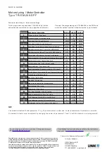
Fejludlæsning /
Error read out
Fejludlæsning /
Error read out
Note 1)
Til aktuatorer produceret
før d.15-10-2014
anvend
Hvid
leder.
Use the
White wire for Actuators produced
before
15-10-2014.
Hall A
Hall B
H
H
Terminal
LA23 Hall LA31 Hall LA36 Hall
0V -
1
Actuator -
2
BL
BL
BL
Ac
3
BR
R
BR
24V +
4
5
R
OR
R
6
GU
GU
GR
7
GR
GU
8
S
S
9
10
11
12
13
14
4 +
+ BR
1 -
- S
EM-311-DK
Blink/
Flashes
Betydning
Meaning
1
Strømgrænse nået (overstrøm)
Power limit reached (overcurrent)
2
Fejl på tilbagemeldingen
Pulse lost
3
Slået fra pga. varme
Cut off on over heat protection
4
Slået fra pga. overstrøm
Cut off on overvoltage
5
Time out
Time out
6
Fejl under læringsprocedure
Learn corrupted
Flashes


