background image

CV  ADAPTER 

TM

OPERATOR’S MANUAL

IM309-D

January, 2005

Safety Depends on You

Lincoln arc welding and cutting
equipment is designed and built
with safety in mind. However,
your overall safety can be
increased by proper installation
... and thoughtful operation on
your part. DO NOT INSTALL,
OPERATE OR REPAIR THIS
EQUIPMENT WITHOUT READ-
ING THIS MANUAL AND THE
SAFETY PRECAUTIONS CON-
TAINED THROUGHOUT. And,
most importantly, think before you
act and be careful.

• Sales and Service through Subsidiaries and Distributors Worldwide •

Cleveland, Ohio 44117-1199  U.S.A.   TEL: 216.481.8100   FAX: 216.486.1751   WEB SITE: www.lincolnelectric.com

• World's Leader in Welding and Cutting Products •

Copyright © 2005 Lincoln Global Inc.

Summary of Contents for CV ADAPTER

Page 1: ...ation on your part DO NOT INSTALL OPERATE OR REPAIR THIS EQUIPMENT WITHOUT READ ING THIS MANUAL AND THE SAFETY PRECAUTIONS CON TAINED THROUGHOUT And most importantly think before you act and be careful Sales and Service through Subsidiaries and Distributors Worldwide Cleveland Ohio 44117 1199 U S A TEL 216 481 8100 FAX 216 486 1751 WEB SITE www lincolnelectric com World s Leader in Welding and Cut...

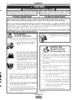
Page 2: ...CEMAKER WEARERS SHOULD CONSULT WITH THEIR DOCTOR BEFORE OPERATING Read and understand the following safety highlights For additional safety information it is strongly recommended that you purchase a copy of Safety in Welding Cutting ANSI Standard Z49 1 from the American Welding Society P O Box 351040 Miami Florida 33135 or CSA Standard W117 2 1974 A Free copy of Arc Welding Safety booklet E205 is ...

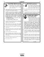
Page 3: ...electrical earth ground 3 f Maintain the electrode holder work clamp welding cable and welding machine in good safe operating condition Replace damaged insulation 3 g Never dip the electrode in water for cooling 3 h Never simultaneously touch electrically hot parts of electrode holders connected to two welders because voltage between the two can be the total of the open circuit voltage of both wel...

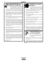
Page 4: ... to prevent the welding sparks from starting a fire Remember that welding sparks and hot materials from welding can easily go through small cracks and openings to adjacent areas Avoid welding near hydraulic lines Have a fire extinguisher readily available 6 b Where compressed gases are to be used at the job site special precautions should be used to prevent hazardous situations Refer to Safety in ...

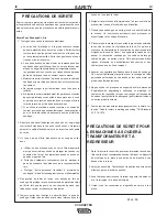
Page 5: ...propriés et non inflammables 4 Des gouttes de laitier en fusion sont émises de l arc de soudage Se protéger avec des vêtements de protection libres de l huile tels que les gants en cuir chemise épaisse pan talons sans revers et chaussures montantes 5 Toujours porter des lunettes de sécurité dans la zone de soudage Utiliser des lunettes avec écrans lateraux dans les zones où l on pique le laitier 6...

Page 6: ...formation below for future reference This information can be found on your machine nameplate Product _________________________________________________________________________________ Model Number ___________________________________________________________________________ Code Number or Date Code_________________________________________________________________ Serial Number_________________________...

Page 7: ...lassic I Engine Welder B 9 K384 CV Adapter to Classic II Engine Welder B 11 K385 1 Model B 12 K385 1 CV Adapter to SAE 300 SAE 400 or SAE 400 WELD N AIR Engine Welders B 13 Operation Section C VV or CV Welding All Power Sources C 1 VV Stick Welding All Power Sources C 1 CV Innershield Welding SA 200 and SA 250 C 1 CV Innershield Welding SAE Engine Welders C 1 Troubleshooting Section D Diagrams Sec...

Page 8: ...der current rating The table gives a summary of CV outputs when the Adapter is connect ed NOTE WHEN ENGINE WELDER IS SUPPLIED WITH A METER THE AMMETER DOES NOT WORK WHEN WELDING IN THE CV MODE The CV Adapter will fit any of the following engine welders SA 200 with electronic idler and FDW DC exciter above Code 7240 Classic I and II Below Code 10066 SA 250 above Code 7826 and Below code 10066 SAE 3...

Page 9: ...h an adapter plate A control cable is used to connect the CV Adapter to the welder control circuit and the output ter minals A power cable is used to connect the CV out put terminal of the Adapter to the welder negative brushholder This connection by passes the series field for CV operation A thermostat assembly is sent with the Adapter model for the SA 200 and SA 250 to pro tect the welder if ove...

Page 10: ...S LISTED IN ENGINE WELDER OPERATING MANUAL The following tools and materials are recommended for attaching the CV Adapter to an engine welder 1 Measuring tape hammer center punch and electric drill with 13 32 drill bit This is only needed for SA 250 engine welders that do not have mounting holes in fuel tank rail 2 Set of socket wrenches 3 11 32 wrench and 3 8 nut driver or pliers 4 1 2 open end w...

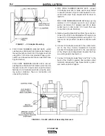
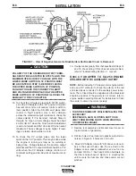
Page 11: ... Current Adjustment rheostat Connect CV Adapter lead 600 to the end terminal of the Fine Current Adjustment rheostat that has an existing lead connected to it 7 Connect CV Adapter leads Neg and Pos to the back of the SA 200 negative and positive output terminals respectively Tape these leads to gener ator lead bundle for support FIGURE 1 CV Adapter Mounting FIGURE 2 SA 200 with Roof Assembly Remov...

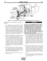
Page 12: ...tape 11 Replace the roof assembly and bracket cover removed in Step 1 POLARITY OF THE STANDARD OUTPUT TERMI NALS MUST BE AS STATED IN STEP 12 AND THE MAXIMUM OPEN CIRCUIT VOLTAGE WITH THE LOWER MODE SWITCH IN CV POSITION MUST BE AS STATED IN STEP 13 BEFORE PLACING THE UPPER MODE SWITCH IN CV POSITION FAILURE TO HAVE THE CORRECT POLARITY AND VOLTAGE BEFORE PLACING THE UPPER MODE SWITCH IN CV POSITI...

Page 13: ...sting push on terminal Tape up connection and unused ring terminal Rectifier located on back of control panel See Figure 4 5 Tape up ring terminal on CV Adapter lead 610 and connect push on terminal of CV Adapter lead 610 to black lead on positive terminal of rectifier 6 Remove existing field lead from the center terminal of the Fine Current Adjustment rheostat and con nect it to the CV Adapter le...

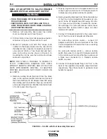
Page 14: ...with hardware supplied to connect the 2 heavy cable from the CV Adapter to the free end of the thermostat assembly from Step 9 The flat side of the cable lug should be against the bottom side of the thermo stat assembly with the nut washer and lockwash er on the top 11 Connect leads 608 and 609 routed into the gener ator in Step 10 to the two thermostat terminals 12 Disconnect the white and yellow...

Page 15: ...s when the CV Adapter voltage control is at minimum setting and 36 48 volts at maximum set ting 16 If output varies greatly from that specified in Steps 14 and 15 check wiring If this does not solve problem refer to Troubleshooting Section of manual K384 CV ADAPTER TO SA 250 ENGINE WELDER WITH DC AUXILIARY OUTPUT NOTE Before installing CV Adapter start engine welder and use a DC voltmeter to check...

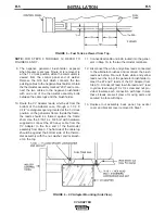
Page 16: ...g blue field lead from the center ter minal of the Fine Current Adjustment rheostat and connect it to CV Adapter lead 503 using 10 x 1 4 screw and nut provided Insulate connection with tape For units with remote control leave blue lead from remote switch in place on center terminal of rheostat 7 Connect CV Adapter lead 602 to the center termi nal of the Fine Current Adjustment rheostat For units w...

Page 17: ... see Figure 10 is removed is at the 11 o clock position when the commutator is viewed from the control panel end of welder Remove the 5 16 bolt which connects the two existing cables to the negative brushholder Locate the thermostat assembly marked 250 and recon nect the two cables to the negative brushholder with one end of the thermostat assembly bolted between the cable lugs and the brushholder...

Page 18: ... This may be done while the engine is running as long as no welding is being done Voltage between the positive output terminal and the CV output terminal should be 7 12 volts DC when the CV Adapter voltage control is at minimum setting and 36 48 volts DC at maximum setting 15 If output varies greatly from that specified in Steps 13 and 14 check wiring and refer to troubleshoot ing section of manua...

Page 19: ... assembly from Step 8 The flat side of the cable lug should be against the bottom side of the thermo stat assembly with the nut washer and lockwasher on the top 10 Connect leads 608 and 609 routed into the gener ator in Step 9 to the two thermostat terminals Use tape to separately insulate the unused Y and W leads Insure that all leads are well clear of moving parts and secured in place with tape ...

Page 20: ...nal of rectifier 5 Remove existing field lead from the center terminal of the Fine Current Adjustment rheostat and con nect it to the CV Adapter lead 503 using 10 24 x 1 4 screw and nut provided Insulate the connec tion with tape For units with remote control leave blue lead from remote switch in place on center terminal of rheostat 6 Connect CV Adapter lead 602 to 602 on the ter minal strip Also ...

Page 21: ...BEFORE PLACING THE UPPER MODE SWITCH IN CV POSITION WILL RESULT IN DAM AGE TO THE CV ADAPTER 13 To check the VV output place both CV VV switch es on the CV Adapter in the VV position If welder has remote control set remote control switch to local position Start the Classic II and place idler control in high position Use a DC voltmeter across the standard output terminals to check the output polari...

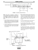
Page 22: ...e positioned flush against the fuel tank rail Take care not to pinch any leads or lines NOTE FOR STEPS 3 THROUGH 13 REFER TO THE PROPER CONNECTION DIAGRAM IN THIS MANU AL FOR THE WELDER WITH THE APPROPRIATE TYPE OF AUXILIARY POWER AND CODE NUMBER CV ADAPTER CONTROL LEADS ARE NOT COLOR CODED ON ALL UNITS 3 Remove existing yellow lead from the outside ter minal of the reversing switch and connect it...

Page 23: ...flashing diode lead Insulate lead 613 with tape FIGURE 13 Frame Rail Mounting FIGURE 14 View of Negative Generator Brushholder after Bracket cover is Removed 7 For code 8812 through 10400 10549 and 10664 10665 Route CV Adapter leads 600 602 610 612 and 613 through plastic lead clamp on Current Control reactor housing Connect CV Adapter lead 602 to the center terminal of the Job Selector rheostat F...

Page 24: ...ge D1 neg ative and the control panel ground screw with the diode lead assembly provided with the K385 1 CV Adapter Disconnect the white flashing diode lead from the white hour meter lead at the taped junc tion the flashing diode is mounted on the inside of the reactor box located behind the control panel Connect the CV Adapter leads 611 to the white flashing diode lead 612 to the white hour meter...

Page 25: ...are clear of any sharp edges on the guards POLARITY OF THE STANDARD OUTPUT TERMINALS MUST BE AS STATED IN STEP 16 AND THE MAXIMUM OPEN CIRCUIT VOLTAGE WITH THE LOWER MODE SWITCH IN CV POSITION MUST BE AS STAT ED IN STEP 17 BEFORE PLACING THE UPPER MODE SWITCH IN CV POSITION FAILURE TO HAVE THE CORRECT POLARITY AND VOLT AGE BEFORE PLACING THE UPPER MODE SWITCH IN CV POSITION WILL RESULT IN DAMAGE T...

Page 26: ...ork using the spring clip on the end of the lead The output voltage is set with the voltage control dial on the CV Adapter Set the welder Current Range Selector to the 190 120 position for optimum welding characteris tics with Innershield electrodes Changing the Current Range Selector affects arc characteristics The setting of the Fine Current Adjustment does not affect the opera tion in CV mode W...

Page 27: ...hat best describes the symptom that the machine is exhibiting Step 2 RECOMMENDED COURSE OF ACTION This column provides a course of action for the Possible Cause If you do not understand or are unable to perform the Recommended Course of Action safely contact you local Lincoln Authorized Field Service Facility HOW TO USE TROUBLESHOOTING GUIDE Service and Repair should only be performed by Lincoln E...

Page 28: ... discon nect one side of flashing diode On SAE 300 SAE 400 and SAE 400 WELD N AIR machines above Code 8812 or SAE 350 machines also disconnect SAE green lead from CV Adapter lead 613 NOTE ON SAE UNITS BELOW CODE 9936 THE SAE GREEN LEAD WAS RED Reconnect the above items after trouble is determined and resolved B For Codes 10601 10602 10856 10884 and 10885 Verify that the diodes in the lead between ...

Page 29: ... units with remote control Remote Control Switch set in the wrong position A Mode switch in wrong position B Output connected to wrong output terminal C In CV mode standard current control or range selector in wrong position See operating manual D Check bank of capacitors in CV Adapter control box A failure is indi cated if the small vent plug on top of a capacitor is raised or blown out Replace e...

Page 30: ...E 1 DIAGRAMS E 1 CV ADAPTER CONNECTION DIAGRAM CV ADAPTER TO SA 200 BELOW CODE 8678 CONNECTION DIAGRAM CV ADAPTER TO SA 200 ABOVE CODE 8678 S17514 A S17515 A ...

Page 31: ...E 2 DIAGRAMS E 2 CV ADAPTER CONNECTION DIAGRAM CV ADAPTER TO SA 250 WITH AC AUXILIARY POWER CONNECTION DIAGRAM CV ADAPTER TO SA 250 WITH DC AUXILIARY POWER S17517 A S17516 A ...

Page 32: ...IAGRAMS E 3 CV ADAPTER CONNECTION DIAGRAM CV ADAPTER TO SA 250 WITH AC AUXILIARY POWER AND REMOTE CONTROL CONNECTION DIAGRAM CV ADAPTER TO SA 250 WITH DC AUXILIARY POWER AND REMOTE CONTROL S17766 A S17765 A ...

Page 33: ... CV ADAPTER TO SAE 300 OR SAE 400 ENGINE WELDER WITH AC AUXILIARY POWER FOR CODES 7160 TO 8812 CONNECTION DIAGRAM CV ADAPTER TO SAE 300 OR SAE 400 ENGINE WELDER WITH AC AUXILIARY POWER FOR CODES 8812 THROUGH 10400 10549 and 10664 S17519 A S17561 A ...

Page 34: ...W N U 600 602 613 503 509 TO RECEPTACLES TO ALTERNATOR N G G G POS CV ADAPTER TO NEGATIVE BRUSH HOLDER Y B NEG 1 B 2 3 4 B SEE BATTERY WIRING DIAGRAM R 2CR BACK VIEW OF POLARITY SWITCH WELD CURRENT ELECTRODE G SENSING SWITCH S W 24465 REACTOR TO WORK TERMINAL POS NEG 1 F 611 610 GROUND SCREW TO LOWER PANEL GROUND SCREW G B W POLARITY SWITCH D1 R AC AC 500 Y R W REMOTE CONTROL RECEPTACLE AND SWITCH...

Page 35: ...nd plug rated at 115 volts 15 amperes AC N C Plug into 115 volt AC receptacle on welder control panel or other 115 volt AC supply rated a minimum of 500 volt amperes N D Leads 21 and GND do not appear on LN 7 s with codes below 7026 N E Welding cables must be of proper capacity for the current and duty cycle on immediate and future applications N F If LN 7 is equipped with a meter kit extend lead ...

Page 36: ...E 7 DIAGRAMS E 7 CV ADAPTER CV ADAPTER WIRING DIAGRAM FOR SA 200 SA 250 CLASSIC I AND CLASSIC II M14822 A ...

Page 37: ...E 8 DIAGRAMS E 8 CV ADAPTER CV ADAPTER WIRING DIAGRAM FOR SAE 300 SAE 350 SAE 400 AND 450 SAE M15198 A ...

Page 38: ... ENGINE DRIVEN ARC WELDING POWER SOURCES MAINTENANCE INSTRUCTIONS IN THE OPERATING MANUAL GREASE MAY BE ADDED TO BEARINGS NO MORE THAN ONCE A YEAR SEE INSTRUCTIONS SEE THE OPERATING MANUAL FOR INSTRUCTIONS REPLACE BRUSHES BEFORE THE PIGTAIL IS WITHIN 25 OF THE COMMUTATOR CLEAN COMMUTATORS OR SLIP RINGS WITH FINE SANDPAPER NOT EMERY CLOTH SEE THE OPERATING MANUAL FOR INSTRUCTIONS BLOW DUST FROM THE...

Page 39: ...BUTOR IGNITION RESISTOR FUEL SHUT OFF CARBURETOR BAT A L8984 B R POS BUTTON IDLER CONTROL P C BOARD START BATTERY AMMETER U B H IDLER SOLENOID MOTOR START G H B R Y ALTERNATOR EXC OIL PRESSURE Y SWITCH AUX POWER RECEPTACLE B R B E E E TO EXCITER OUTPUT N Y R W B B Y B 600A 41 OIL PRESSURE LIGHT ENGINE HOUR METER IDLER CONTROL SWITCH 42 RHEOSTAT 1 2 3 4 5 A F R N N U U CR2 REED RELAY W W Y Y 608 60...

Page 40: ...CONTROL PANEL SWITCH COPPER TERMINAL GROUND TERM WIDE SLOT W G CONNECT TO CASE PLUG FOR REMOTE CONTROL POTENTIOMETER REMOTE CONTROL POTENTIOMETER BOX B WITH MACHINE NOT RUNNING REMOVE JUMPER 42 TO 600 AT THE TERMINAL STRIP CONNECT THESE LEADS STRIP TO THE CORRESPONDING NUMBERS AT THE TERMINAL CONTROL PANEL COMPONENTS SHOWN AS VEIWED FROM REAR LEAD COLOR CODE B BLACK G GREEN N BROWN R RED U BLUE W ...

Page 41: ...EMOTE CONTROL PANEL SWITCH COPPER TERMINAL GROUND TERM WIDE SLOT W G CONNECT TO CASE PLUG FOR REMOTE CONTROL POTENTIOMETER REMOTE CONTROL POTENTIOMETER BOX B WITH MACHINE NOT RUNNING REMOVE JUMPER 42 TO 600 AT THE TERMINAL STRIP CONNECT THESE LEADS STRIP TO THE CORRESPONDING NUMBERS AT THE TERMINAL CONTROL PANEL COMPONENTS SHOWN AS VIEWED FROM REAR LEAD COLOR CODE B BLACK G GREEN N BROWN R RED U B...

Page 42: ...E 13 DIAGRAMS E 13 CV ADAPTER CV ADAPTER SCHEMATIC L6922 A ...

Page 43: ......

Page 44: ...touch electrically live parts or electrode with skin or wet clothing Insulate yourself from work and ground No toque las partes o los electrodos bajo carga con la piel o ropa moja da Aislese del trabajo y de la tierra Ne laissez ni la peau ni des vête ments mouillés entrer en contact avec des pièces sous tension Isolez vous du travail et de la terre Berühren Sie keine stromführenden Teile oder Ele...

Page 45: ...e für gute Be und Entlüftung des Arbeitsplatzes Mantenha seu rosto da fumaça Use ventilação e exhaustão para remover fumo da zona respiratória Turn power off before servicing Desconectar el cable de ali mentación de poder de la máquina antes de iniciar cualquier servicio Débranchez le courant avant l entre tien Strom vor Wartungsarbeiten abschalten Netzstrom völlig öff nen Maschine anhalten Não op...

Page 46: ...s and Service through Subsidiaries and Distributors Worldwide Cleveland Ohio 44117 1199 U S A TEL 216 481 8100 FAX 216 486 1751 WEB SITE www lincolnelectric com World s Leader in Welding and Cutting Products ...

Reviews: