


QUICK START GUIDE FOR DEMONSTRATION CIRCUIT 1317A-A
ACTIVE RESET ISOLATED 48V INPUT TO 3.3V @30A DC/DC POWER CONVERTER
1
LT1952
DESCRIPTION
DESCRIPTION
DESCRIPTION
DESCRIPTION
Demonstration circuit 1317A-A is isolated input to
high current output 1/8th Brick footprint
1/8th Brick footprint
1/8th Brick footprint
1/8th Brick footprint converter
featuring the LT
®
1952 switching controller with Ac-
tive Reset circuit. The Active Reset circuit can im-
prove the efficiency in wide input voltage applica-
tions. Also, the Active Reset allows the implementa-
tion of self-driven synchronous secondary rectifiers
in some applications.
The DC1317A-A converts isolated 34V to 75V input to
3.3V output and provides over 30A of output current.
The converter operates at 300kHz with the peak effi-
ciency greater than 93%. The DC1317 can be easily
modified to generate output voltages in the range
from 0.6V to 48V. The output currents are limited by
total output power of up to 150W.
The other available versions of DC1317A are:
DC1317A-B, 18-72Vin to 5V, 25A
DC1317A-C, 18-72Vin to 12V, 10A
DC1317A-D, 18-72Vin to 24V, 5A
DC1317A-E, 36-72Vin to 5V, 12A
DC1317A-F, 9-36Vin to 3.3V, 20A
DC1317A-G, 9-36Vin to 12V, 5A
DC1317A-H, 9-36Vin to 48V, 1.5A
The DC1317 circuit features soft-start which prevents
output voltage overshoot on startup or when recover-
ing from overload condition.
The DC1317 has precise over-current protection cir-
cuit that allows for continuous operation under short
circuit conditions. The low power dissipation under
short circuit conditions insures high reliability even
during short circuits.
The LT1952 can be synchronized to an external clock
of up to 400kHz. Please refer to LT1952 data sheet for
design details and applications information.
Design files for this circuit board are avai
Design files for this circuit board are avai
Design files for this circuit board are avai
Design files for this circuit board are availlllable.
able.
able.
able.
Call the LTC factory.
Call the LTC factory.
Call the LTC factory.
Call the LTC factory.
LT is a trademark of Linear Technology Corporation
Table 1.
Table 1.
Table 1.
Table 1.
Performance Summary
Performance Summary
Performance Summary
Performance Summary
PARAMETER
PARAMETER
PARAMETER
PARAMETER
CONDITION
CONDITION
CONDITION
CONDITION
VALUE
VALUE
VALUE
VALUE
Minimum Input Voltage
IOUT = 0A to 30A
34V
Maximum Input Voltage
IOUT = 0A to 30A
75V
VOUT
VIN = 34V to 75V, IOUT = 0A to 30A
3.3V ±3%
Typical Output Ripple VOUT
VIN = 34V to 75V, IOUT = 0A to 30A
50mVP–P
Nominal Switching Frequency
300kHz
QUICK START PROCEDUR
QUICK START PROCEDUR
QUICK START PROCEDUR
QUICK START PROCEDURE
E
E
E
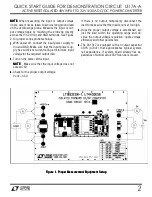
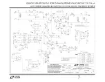
Demonstration circuit 1317 is easy to set up to evalu-
ate the performance of LT1952 circuit. Refer to Fi
Refer to Fi
Refer to Fi
Refer to Fig-
g-
g-
g-
ure 1 for proper measurement equipment setup
ure 1 for proper measurement equipment setup
ure 1 for proper measurement equipment setup
ure 1 for proper measurement equipment setup
and follow the procedure below:


