background image

Instruction Manual

The 8th Edition

CAN/LIN Data Logger

LE-270AR

LE-270GR

The attached CD-ROM contains the latest instruction manual in a PDF format. 

Summary of Contents for LE-270AR

Page 1: ...Instruction Manual The 8th Edition CAN LIN Data Logger LE 270AR LE 270GR The attached CD ROM contains the latest instruction manual in a PDF format ...

Page 2: ...ion Condition 17 4 2 Start and Stop Measurement 20 4 3 Watch Data Display 24 4 4 Analog Waveform Display 25 Chapter 5 Simulation Function 26 5 1 Simulation Table Setting 26 5 2 CAN Table Setting 26 5 3 CAN Simulation 28 5 4 LIN Table Setting 29 5 5 LIN Simulation 29 Chapter 6 Useful Functions 31 6 1 Trigger Function 31 6 2 Text Conversion 32 Chapter 7 Data Logger Mode 33 7 1 Preparation of Data Lo...

Page 3: ...ety aerospace apparatus trunk communication apparatus nuclear control apparatus medical apparatus related with life maintenance and etc Also this product does not warrant the use for those purposes If you use for those purposes please consider the safety measures against fail safe etc on your responsibility This product has Wi Fi function IEEE 802 11b g n and emits radio wave when working Please d...

Page 4: ...a rapid temperature change The places with much dust and moisture The places near the objects which generate heat the heater etc Using in these places may result unit malfunction and or injury This Safety Information includes the important information in order to not only have you learn the right way to use the analyzer but also prevent you from causing damage to people and property Before using p...

Page 5: ...e This software may be upgraded without advance notice because of technical progress of hardware or software LINEEYE provides software upgraded by payment specially For upgrade only licensed user can have upgrades 5 Limitation of Liability In no event shall LINEEYE or its licensors be liable for loss of business or profits or for any direct indirect incidental or consequential damages arising from...

Page 6: ...ww lineeye com 1 2 Outline Functions 1 On line Monitoring Monitor the transmission reception data on line to check the existence of hindrance and communication data in the line or to analyze the communication 2 Simulation function The product takes a role of a node of CAN LIN and transmits the data frame or remote frame set by the user 3 Analog measurement function The product measures and records...

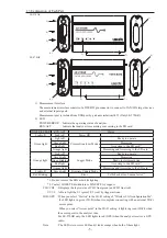
Page 7: ...D lights in green Wi Fi when it completes connecting with an external Wi Fi access point When you select Access point in the Wi Fi setting it lights in green Wi Fi when the access point in the analyzer runs For LE 270GR only the LED lights in red GPS when the analyzer receives a GPS radio Note The LED is two colors LED and it looks orange when both of them light POWER ERROR RUN ACT Status Light of...

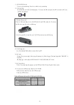
Page 8: ...er 6 DC Jack Connect the power supply when using the analyzer as a Data Logger Optional plug cable SIH 2PG is available DC plug type center plus outside diameter 5 5mm inside diameter 2 1mm 7 M3 Screw Hole This is for connecting the analyzer on the DIN rail Pitch 70mm Depth 3 5mm max 8 Connector for GPS antenna Only for LE 270GR SMA connector female for active GPS antenna Connect a GPS antenna Maj...

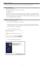
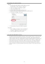
Page 9: ...product is needed to be compliant with RE directive 2014 53 EU Chapter 2 Installation Install the analysis software LE LIK27R to the PC you are going to operate the analyzer 2 2 Installation of USB Driver Windows7 8 1 10 A screen is an example of Windows10 1 Insert the included CD ROM into the CD ROM drive 2 Open the folder or Drives and click setup exe Click Yes when following dialog is appeared ...

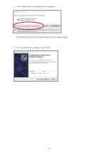
Page 10: ... 8 6 After installation has completed click Finish 5 Click Install and start installing the driver package Mark on the check box and the same dialog will not be appeared again ...

Page 11: ... two days in the power off condition When the analyzer is powered for hours the battery will be fully charged and the date and time in the RTC will be kept for more than 6 months Uninstall 1 Open Add Remove Application in the Control Panel It might be Add Remove Programs for other OS 2 Select LE LINK27R and execute Remove 2 3 Installation of the Analysis Software Install 1 Insert the included CD R...

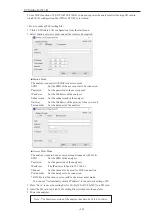
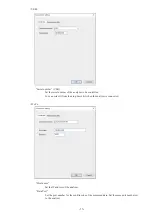
Page 12: ...r Gateway Set the IP address of the gateway when you use it Port number Set the data port of the analyzer Access Point Mode The analyzer turns to be an access point and connects with Wi Fi SSID Set the SSID of the analyzer Password Set the password of the analyzer IP address The IP address is fixed to 192 168 4 1 Channel Set the channel to be used for Wi Fi connection Port number Set the data port...

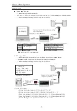
Page 13: ...ion connect following signals Signal Meaning CAN_H CAN Bus signal CAN_L GND Signal Ground Note Low Speed CAN is not supported For LIN communication connect following signals Signal Meaning BATT Battery Power 9 18V LIN LIN Bus signal GND Signal Ground SHI 2PG Connect the black white cable to the positive electronic pole of DC power External power supply External power supply range for DC IN is from...

Page 14: ...e measured data 4 Data Position Display Display the data file name and data position of Data display The number of data loss will be displayed while monitoring 5 Model Name Display Display the model name of analyzer 1 2 3 4 5 Connection Settings Click on the tool bar of the data window or Measurement Connection setting and set the connection settings and data saving settings The connection setting...

Page 15: ...zer to be controlled You can select it from the drop down list when the analyzer is connected Wi Fi Host name Set the IP address of the analyzer Data Port Set the port number for the send receive of the measured data Set the same port number set to the analyzer ...

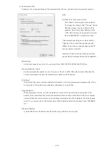
Page 16: ...n select from 128K 1M 2M 4M 8M 16M 32M byte Maximum Block Count Set the maximum file number to save You can set from 2 to 1000 When the number of the data file exceeds this number the data file with the lower number will be deleted Full Stop If the stored files reach to the maximum block number it will stop measurement automatically If you do not select it the analyzer records data continuously as...

Page 17: ...tion 1 function interpolation function for GPS data 1 2 and capture control at staring the measurement 2 1 GPS function is available only in LE 270GR It is able to set GPS Acceleration function in LE 270AR however it cannot be performed 2 Firmware version 1 02 or above is required ONLINE Online mode Monitor CAN LIN data ANALOG Analog mode Record 4 external signal voltage at specified sampling 1ms ...

Page 18: ... data table Table 0 to F Set the frame to be sent Note When it is LIN master simulation you can set the schedule setting from function selection display Logger Setting Data Save Set the file size and number of files to save for a Data Logger Mode Auto RUN STOP Set the starting time and ending time of the auto measurement ...

Page 19: ... specific communication can be set 4 1 Communication Condition Click on the tool bar of the data window or click Measurement Measurement setting Set the communication condition for target devices CAN setting Baud Rate The analyzer measures data at the preset Bit timing Bit timing is set as 75 of the bit To change the Bit timing press Custom SS PTS PBS1 PBS2 1TQ 5TQ 3TQ 3TQ Base Frequency Frequency...

Page 20: ...es with ID 010h HEX Note When extended format are mixed with standard format 00400000h 0043FFFFh also will be captured PASS Captures the frames which have corresponding ID by a software filter Select standard format of extended format at the pass configuration tab and set the ID by HEX 0 F Don t care You can set up to 8 items Configure values within the scope of ID 0 7FFh when it is standard forma...

Page 21: ... format of extended format at the cut configuration tab and set the ID by HEX 0 F Don t care You can set up to 8 items Configure values within the scope of ID 0 7FFh when it is standard format and configure values within the scope of ID 0 1FFFFFFFh when it is extended format Note If there is no entry for the blanks when the cut filter is valid all the ID frame will be captured Example Cuts the IDs...

Page 22: ...3Fh have to be calculated by Classic ID settings ID settings have to be set only when ID is selected in the Frame End setting Set the data length DLC 0 8 byte and method of calculating checksum Classic or Enhanced for each frame in the ID 00h 3Fh 4 2 Start and Stop Measurement Start Measuring Click on the tool bar of data window or click Measurement Run measurement Watch Data display is also avail...

Page 23: ...t in the Data Monitor display Data will be saved into the specified folder set in the configuration settings To open the previous files click or File Data file and specify the file To open the sequential order files click or Please make sure that power saving mode of the PC does not cut USB connection It will end the measurement of analyzer ...

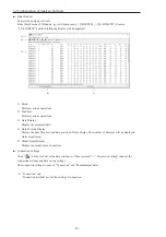
Page 24: ...e contents of the data field in HEX FC CAN 2 byte CRC LIN Checksum in HEX I1234 From left to right digital value of EXIN1 EXIN2 EXIN3 EXIN4 in binary 0 Low 1 High Measured voltage value of the timing when it received the frame 0 1 0V or less 1 2 3V or more AI1 AI4 Analog value of EXIN1 EXIN4 15V 15V Voltage value of the timing when it received a frame unit V TRG Frame which triggered by trigger fu...

Page 25: ...eans the buffer in the analyzer becomes full while measuring Data Position It displays the number of data loss Analyzer cannot save data in the SD card or HDD of PC because of the baud rate and large amount of data while measuring LOSTDATA will be displayed in the monitor display After the measurement it will display the position of top of data displayed in the monitor display If the Capture Contr...

Page 26: ...N 0 3Fh Include all frames Uncheck It displays normal CAN data frames that matched with ID setting No 1 to F or frames with LIN response data Check It displays all frames that matches with ID setting including remotes and errors It cannot find the error status in the Watch Data Display Auto Uncheck It displays frames that matched with the ID setting No 0 to F on the Watch Data Display Column numbe...

Page 27: ...de the latest value would be displayed on the right Now of a graph and be updated every 1 second When displaying the stored data a scroll bar is appeared and it enables scrolling back to the past data 4 4 Analog Waveform Display Display the analog waveform at the specified sampling cycle Analog Waveform Display Analog waveform will be displayed only monitoring at Analog mode or displayed data meas...

Page 28: ...imum 16 in each table The data format to be set differs depending on the protocol CAN or LIN set for the Ch 1 interface 5 2 CAN Table Setting Type Select the frame type Type Description DATA Standard format data frame EX DATA Extended format data frame REMOTE Standard format remote frame EX REMOTE Extended format remote frame ID Set 11 bits 000h to 7FFh for the standard format and 29 bits 00000000...

Page 29: ...e position of the data field where you want to insert the data to be swept For example if the size is 16bit and the position is 2 the gray part will change sweep Data Field The data set in the data item up to 8 bytes is sent except for the set position Initial Set the initial value of the data to be swept in decimal 32768 to 65535 Time 1 3 Set the time to change to the target value values 1 to 3 i...

Page 30: ...sion click the Stop repeated sending toggle button and then click the table number button for which you want to cancel transmission in succession After that click the Stop repeated sending toggle button to return the but ton to the original state Stop the Simulation 1 Close the operation panel 2 Execute Stop measurement If you press Stop measurement without closing the operation panel the operatio...

Page 31: ...ed It is displayed when the response is selected at Type Select whether or not to sweep change continuously the data ON or OFF Make settings in the same way as the sweep function for CAN table settings 5 5 LIN Simulation LIN master simulation or slave simulation is available In the master simulation one touch transmission from the operation panel or automatic transmission are avail able In LIN sim...

Page 32: ...ake Up can transmit a dominant of 0 25μsec or more Dominant time is the time when 1 bit time of the set communication speed is 0 25 μsec or more in total Stop repeated sending cannot be used Master Simulation When the schedule is ON 1 Execute Run measurement 2 Data will be sent automatically in the order set in the schedule table In the protocol analyzer mode only WakeUp 80h and WakeUp can be sent...

Page 33: ...ger independently Each trigger can be set either to be enable or disable Trigger condition Description Error When a communication error occurs Character Detection of specific character ID Detection of specific ID Remote Detection of specific remote frame Timer Counter Timer or counter corresponds with the set value Trigger action Description Stop measurement Stop measurement Timer control Start st...

Page 34: ...format Timestamp is output by difference Output elapsed time stamp from the previous frame If selecting CSV format elapsed time stamp is always output KML It outputs the GPS data latitude longitude as KML format file OBD2 Translate OBD On board diagnostics messages included in the CAN communication data Note The version of the analysis software needs to be Ver1 03 or later Data file list Select th...

Page 35: ... files reaches to the Max Files Append Existing files will not be deleted Record data as a ring mode The file name will be the sequence number after the existing files For 2GB SD card the max file number for saving data will be 512 Max Files Set the max number of files to save File Size Select the file size to save Max Files x File Size will be the capacity of logging data Consider the actual memo...

Page 36: ...ting the measurement and LED of RUN ACT will be lighting The configuration will be sent to the analyzer when switching on the power of analyzer Even you change the SD card after switching on the power the measurement will start according to the configuration of SD card which was set when switching on the power of analyzer The analyzer will not record data if there is not the SD card with configura...

Page 37: ...o make the Wi Fi of the analyzer valid by saving a Wi Fi setting file WLAN CFG WL made by Wireless LAN configuration file to a SD card which is used for the logger mode besides the setting file for the logger mode 2 5 Setting for Wi Fi 1 Input the IP address and port number 2 Click Connect and the list of log files appears Click Update list and the latest ones are displayed on the list window 3 Se...

Page 38: ...rned off after the measurement automatically Power On Run Start measuring when powering on the analyzer Select from Safely start or Quick start For normal operation select Safely start Safely start will start measuring approximately 40 seconds after powering on the analyzer for charging the capacitor for back up data Time stamp information is based on the time of RTC Real Time Clock embedded in th...

Page 39: ...t firmware execute LE8FIRM EXE which is stored in the attached CD ROM Update Firmware Connect the analyzer to the PC 1 Double click on LE8FIRM EXE 2 Select the serial number of the analyzer 3 Click Next 4 Select the downloaded firmware file 5 A note for updating firmware will be displayed Read it carefully and click Start The firmware loader will start operating The LED of POWER ERROR will be ligh...

Page 40: ...2 LIN Signal channel 2 No 4 7 and 22 are connected internally Connect the ground of same electric potential to those pins 9 2 External Input Output Terminal External trigger input output terminal Pin NO Signal name Function Specification 14 TRG_IN External trigger input TTL level input Range 0 5V 6 0V 17 TRG_OT2 External trigger output 2 Open drain output 5V 10KΩ pull up 18 TRG_OT1 External trigge...

Page 41: ...ID don t care available Specified Time stamp External signal Conversion Convert data into Text CSV or KML format and save OBD2 translation External Signal Input Digital Analog 4 channels Recording At the time of receiving signals or specified sampling cycle 1ms 10min 13steps Digital VIH 2V Min VIL 0 5V Max Analog Range 15V to 15V Accuracy 0 5 FS A D Max 50Ksps Resolution 10bit Acceleration data Re...

Page 42: ...e for OBD2 connector 1m Clip cable LE 9LP2 CAN LIN clip monitor cable GPS active antenna EB SL AA170 Supports Beidou GPS and GLONASS Waterproof and dustproof IP65 Available only with LE 270GR DIN rail mounting plate LE DIN13 To connect analyzer on the 35mm DIN rail OBD2 DB25R 1 LE 9LP2 LE 9LP2 female male female SMA connector male GPSantenna ...

Page 43: ...ding to the warranty After the warranty period LINEEYE will repair the product for you to use the functions properly at your own expense If your product needs to be repaired please tell us the model name serial number purchased date and the details of problems User Registration Please register your products from our website We will provide you the update information and so on ...

Page 44: ... 693 0161 Fax 81 75 693 0163 URL https www lineeye com Email info lineeye co jp Printed in Japan LINEEYE CO LTD There is a registration page on our web site https www lineeye com Please register your product for further support We will provide you the firmware update information and sales information etc ...

Reviews: